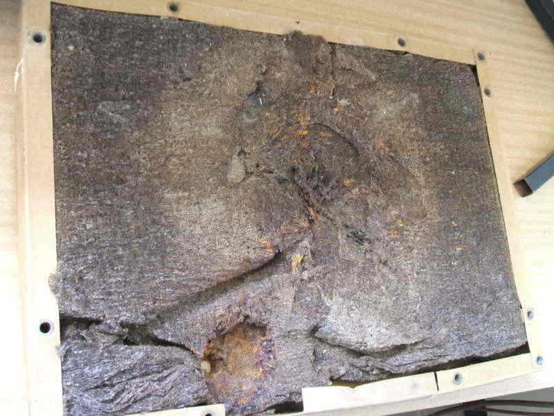
The imprint of the float valve chamber and low side tube are visible in the insulation. It was in good condition.
4.6 Removal of the cabinet top plate.
To do this, the screws around the periphery of the top plate are removed.
The thermostat capillary tube also needs to be removed from the side of
the evaporator. It is then a matter of lifting the plate clear, hooking
it around the severed tubes protruding from the compressor and float valve.
Once the tubes are disconnected, it is necessary to cover the ends
with tape, so as to prevent anything falling in, and to reduce moisture
intake.
5.1. Clean up of cabinet top begins.
The cabinet top is in three sections; the cabinet top plate with the
evaporator bolted to it, the insulation and cardboard surround, and the
cabinet top with float valve and compressor.
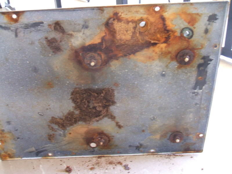
The cabinet top plate was in fairly good condition with minor rust.
The evaporator nuts and washers were all rusted in position.
The insulation looks like an expanded kind of paper and is very soft.
Interestingly, jammed inside was a new rubber grommet for the thermostat.
It had obviously fallen in during manufacture.
The imprint of the float valve chamber and low side tube are visible
in the insulation. It was in good condition.
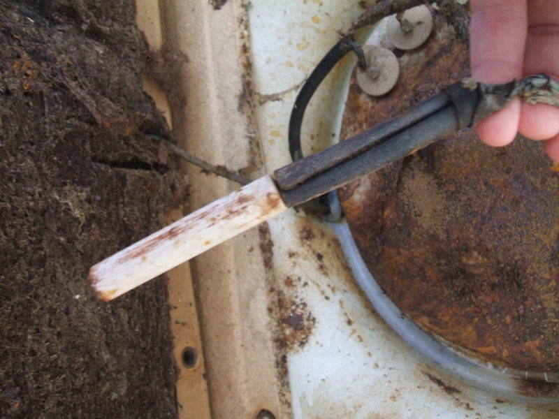
The cabinet top was covered in surface rust. To get the wire brush in there, I removed the old wiring, and the oil heater (which was open circuit). I wrote on the compressor terminals the colours of the attached wires.
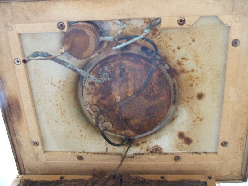
One could assume most restored Monitor Tops are in this condition
inside the cabinet top, as few restorers are prepared to remove the top
plate.
A wire brush in a drill was used to clean off the surface rust and old
caulking compound around the compressor periphery. Next, a problem Id
been aware of since acquiring the fridge had to be fixed. One of the welds
securing the compressor to the cabinet top had broken, possibly due to
prior mishandling. There were three welds all up, but the way they
were positioned meant there would still be a weak spot as there was a large
gap between them on one side. So, I used an arc welder to redo the fractured
weld, and add another so that there were now four equidistant welds around
the compressor. The old caulking compound around the join was replaced
with silicone sealant. The cabinet top needs to be made airtight to prevent
moisture entry which will cause condensation and thus corrosion.
Then I sprayed galvanising paint on the cleaned surfaces, followed
by a coat of white appliance enamel. This improved appearance immeasurably
and should slow down the corrosion considerably.
5.2 Wiring harness.
This was made up of modern plastic three core flex. I found some using
the American colour code of white, black, and green. The green wire was
sleeved with red, so that all colours would match the original.
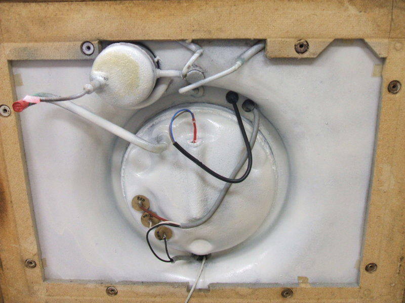
Like new after cleaning up, repainting, and rewiring.
The compressor connections are wires protruding through glass seals,
so its probably wise to apply the soldering iron for the shortest time
possible. The flexible wires are connected to the pins with small brass
ferrules. Where the cable passes through grommets up to the relay and control,
more silicone was used to provide a seal.
The control has a two pin locking plug; the same kind as the power
connection on the start relay. These plugs have screw terminals, as does
the relay box wiring.
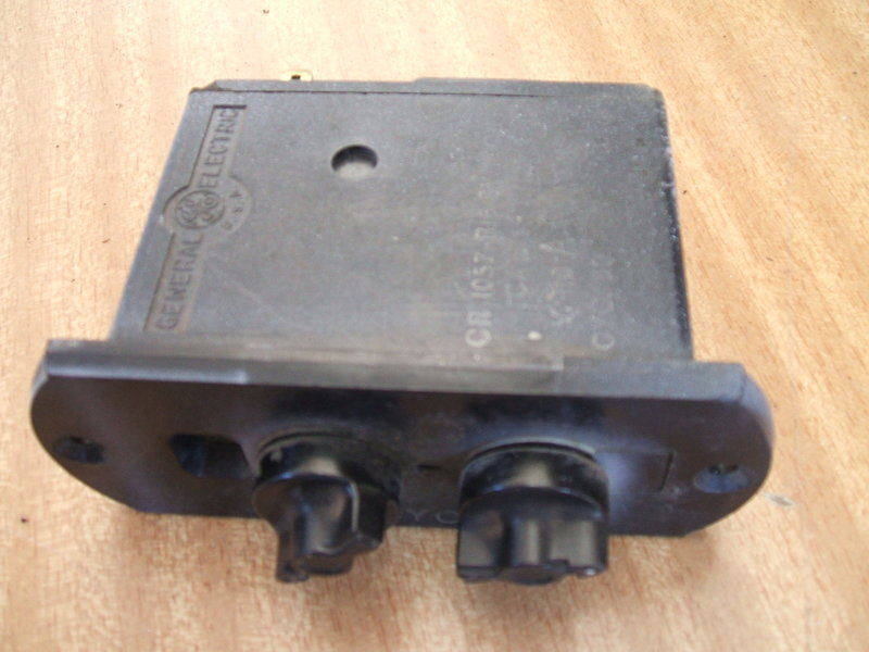
5.3 Start relay repair.
A minor problem was that the outer bobbin cheek of the current coil
had broken off. It could conceivable jam up the relay contacts in the wrong
position, so it was glued back. I used a couple of drops of superglue.
The contacts were in as new condition.
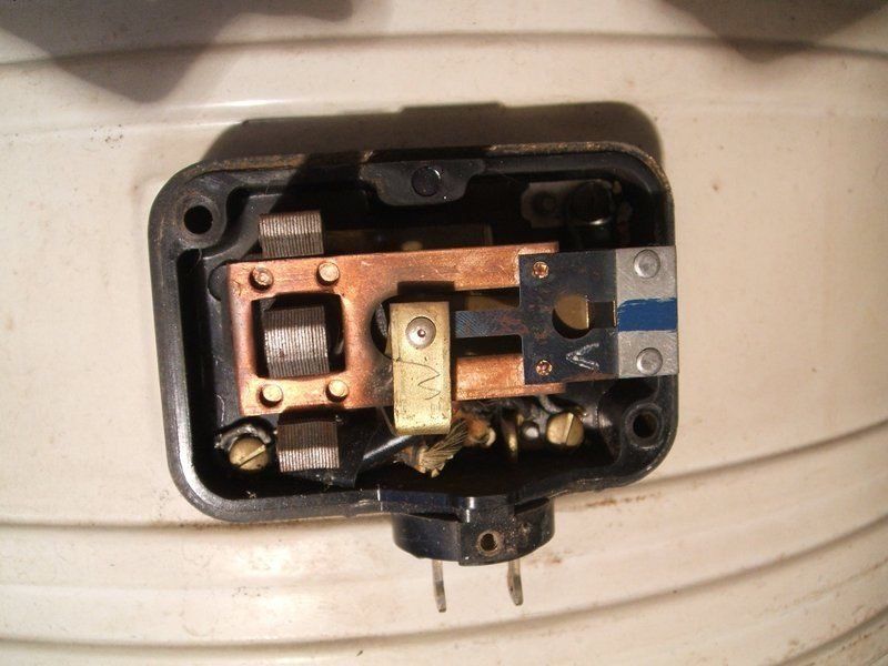
Inside the start relay.
5.4 Oil heater.
One property of Methyl Formate is that it does not mix with the lubricating
oil. It is heavier than the oil, so any methy formate that condenses inside
the compressor will sit beneath the oil. As the CA has the compressor dome
on the high side, it is possible for some methyl formate to condense inside
the dome instead of it all returning to liquid in the condenser. This is
particularly likely to happen with a cool room temperature. It means the
evaporator can be robbed of liquid refrigerant, giving a lower frost line.
The compressor also runs with a rattling sound. To overcome this, a heater
dissipating about 12W is inserted into the bottom of the compressor housing.
It keeps the oil at a temperature at which the Methyl Formate evaporates.
Thus, a CA with poor refrigeration may be suffering from a defective oil
heater.
The heater is a ceramic tube, about 12mm in diameter with flexible
leads attached. I examined the possibility of using a modern equivalent,
which while feasible, was more costly than a solution I had at hand.
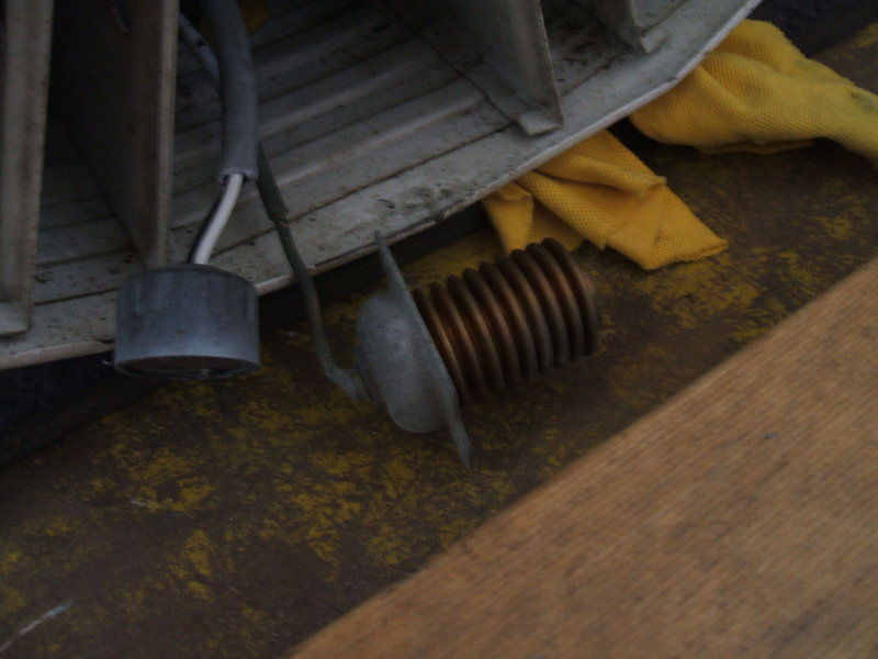
The oil heater is essentially a wire wound resistor inserted into
the compressor body.
My scheme was simply to use a wire wound resistor of around 1000 ohms. At 120V, this value of resistance dissipates 14.4W. I found that 10W resistors would just fit in the compressor well. It was decided to use two in series, thus allowing for 20W dissipation, which meant they would be 560 ohms each. Flexible cable was attached and the resistors soldered together. Quik Steel epoxy was placed between the resistors for insulating the join and providing rigidity. The connection at the far end had to be extended up the side of the resistors. It was insulated in fibreglass tubing and the exposed resistor end covered in Quik Steel. As per the original, solder lugs were attached to the other end of the supply cable for termination in the relay box.
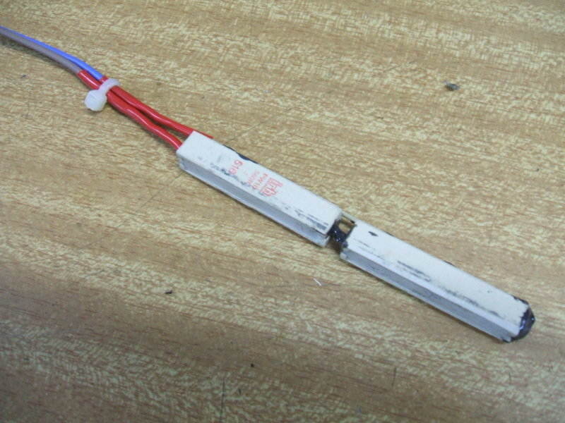
Oil heater made from modern 10W resistors.
As the resistors were a tight fit down the compressor well, the corners were ground off. This would allow easy extraction if any more rust builds up in there. To aid heat transfer, a quantity of heat sink compound was put on the resistors and inside the well. This aids heat transfer by eliminating the air pockets in between the surfaces.
5.5 Top plate repair.
Minor surface rust on the top plate was treated with galvanising
paint.
The rusty nuts had to be cut off the evaporator bolts, which were actually made of aluminium. I used an angle grinder. The rusty surface was cleaned and sprayed with galvanising paint. New 8x30mm cup head bolts in stainless steel were acquired for reattaching the evaporator. (It was later discovered the nuts, bolts, and washers I'd been sold were in fact just zinc plated and had to be later replaced). Given the presence of moisture, and dissimilar metals, there exists the probability of corrosion which is why brass or ordinary steel bolts should not be used. The washers were also replaced. The rubber washers were replaced by cutting new ones from neoprene obtained from Clark Rubber. There is a cork strip between the top of the evaporator and the top plate. It was in good condition. The cork and rubber washers keep the dissimilar metals isolated from each other, as well as insulate the evaporator from the top plate.
6.1 Blowing out the evaporator.
My next plan was to install a T piece and Schrader valve in the low
side line; the T piece being used to rejoin the cut tube. The idea was
that as the charge valve is on the high side line, another valve would
be needed to access the low side for a full evacuation. The vacuum pump
would be connected to both high and low side. A ½T piece with ¼
centre and Schrader valve on a ¼ tail were purchased from Heatcraft.
(Subsequently the idea of adding a Schrader valve was dropped as will be
explained). Before reattaching the evaporator, I thought I should just
blow it out to remove any shavings etc. And here I struck trouble.
6.2 Silver Soldering.
Because of the higher pressures and constant vibration, ordinary 50/50
lead / tin soft solder, as used for domestic plumbing is not suitable.
For refrigeration, silver solder is used. For most copper to copper connections,
solder with 15% silver is used. Its known as brown tip and is self fluxing.
For soldering stainless steel (eg. the evaporator), it is necessary
to use solder with 45% silver content. This is known as blue tip or peach
tip. It requires separate flux.
The higher the silver content, the higher the heat required to solder.
An ordinary butane or propane torch is generally not adequate except for
very small joins. I used a Bernzomatic MAPP gas torch for most of the silver
soldering, but required an oxy/acetylene torch where the copper was thicker
than normal. An oxy/acetylene torch does do a better job because it can
heat the joint up much faster. This means the soldering can be done before
the heat travels down the pipe and possibly weaken other joints, damage
rubber grommets etc. Also, the solder flows better at the higher temperature.
However, an oxy/acetylene torch does require more skill in its use and
there is a real risk of burning a hole if too much heat is used.
A by-product of soldering is the oxidisation that occurs inside the
heated pipe. This is seen as a black flaky coating on the inside of copper
tubing. It is desirable therefore to run nitrogen through the pipes being
soldered to minimise this. Only a small flow is required; just enough to
flow through the pipe.
A wet rag wrapped around the tubing near anything that may be damaged
by heat is another precaution to take. For example, the rubber grommets
in the cabinet top plate, or the float valve outlet.
It is important to ensure no pieces of swarf are left in the tubing.
For this reason, a tube cutter is preferred over a hacksaw.
When soldering Schrader valves remove the valve core. If this is not
done, the seal will be immediately ruined from the heat.
6.3 Blocked evaporator.
Initially I just connected the nitrogen to the high side input, after
removing the damaged high side tube where the kink was. Flexible hose just
blew off the connection, so I then silver soldered a Schrader valve to
it. Even at 400psi there was no flow. The evaporator was completely blocked.
In retrospect, this was a risky move, because had the blockage been on
the low side, the evaporator could have exploded.
How did I know it was the high side? The reason is because pressure
built up immediately. On the low side are two header tanks which would
have allowed a gradual pressure build up. As well, one would be able to
hear the stainless steel flexing under pressure.
Poking wire up the high side tube did not encounter any obstruction.
In fact I was able to feed in about two feet of wire. Injecting paint thinner
into the high side did nothing. Applying a heat gun to the surface whilst
under pressure also did nothing.
I then tried applying low pressure from the low side (about 30psi),
again by soldering a Schrader valve to the connection. This didnt clear
it either, but upon releasing the pressure some oil did squirt out, which
confirmed it was a high side blockage.
Schrader valves were soldered to both evaporator connections to
check for blockage and leakage. Both faults were present with this evaporator.
6.4 Evaporator leak.
It was fortunate that I had applied pressure to the low side connection,
because two leaks were observed, both on the right side header tank where
the ½ tubes were soldered. Oil could be seen bubbling around the
soldered joins. It would appear this was actually where the original Methyl
Formate had been lost. Because of the copper to stainless steel join, it
was necessary to use 45% silver solder. This is known as blue tip. However,
peach tip is equivalent and this is what I was sold. It cost about $14
for a stick. I did try the 15% brown tip but it did not take properly
to the stainless steel.
It could be imagined from the previous mishandling, that resting the
cooling unit on the evaporator could cause side to side flexing and thus
cracks in the soldered joins. The best way to transport the cooling unit
is on its side, with padding under the condenser.
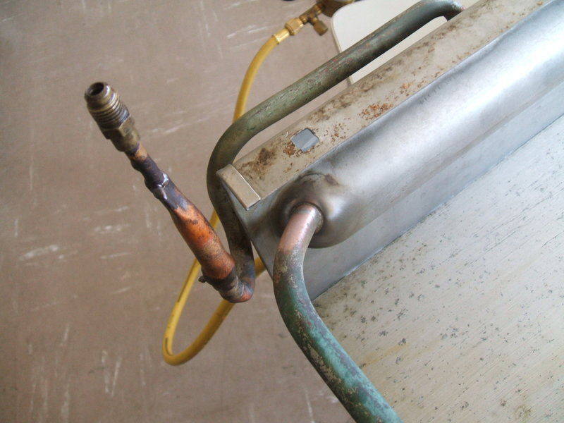
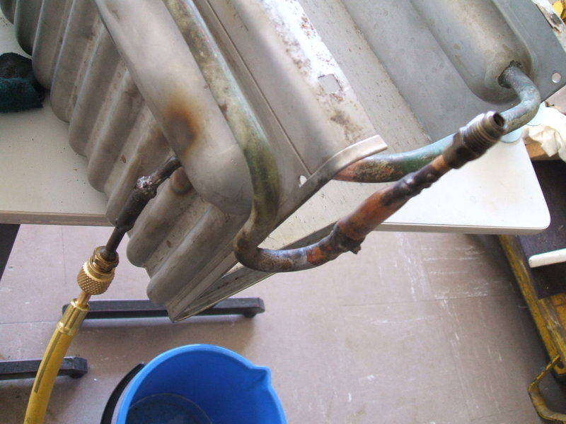
Low side tube/header tank connection cleaned up prior to resoldering.
6.5 Unblocking the evaporator.
Discussion with others had come to the theory that perhaps something
had solidified in the bottom of the evaporator when the Methyl Formate
had left the system, and without the solvent present had solidified. Somewhat
like when a tin of paint is left open and the solvent evaporates leaving
solid dry paint.
A clue to this was given in an email where the author claimed that
lard was added to stabilise the Methyl Formate. Examining the patents confirmed
this. Suggestions were made that the whole evaporator be heated in an oven
while under pressure.
The problem using a heat gun is not only did the evaporator temperature
get up to only 82 degrees C, it was only concentrated in a small area.
While some progress was made using this method, the blockage was still
too severe and not really improving. To determine the amount of blockage,
a tube from the low side had been placed in water; the rate of bubbles
indicating rate of flow.
An oven would overcome this problem. First, a long length of tubing
was soldered to the high side connection. This was to allow the evaporator
to be pressurised from outside the oven if need be, and also kept the Schrader
connector away from the hot surface.
The evaporator was placed in an oven at 100 degrees Centigrade, and
then the temperature was increased to 150 degrees. At 200 degrees, the
oil in the evaporator started smoking so I withdrew it.
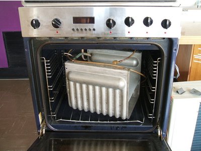
Heating the whole evaporator finally freed the blockage sufficiently.
Applying bursts of nitrogen at 250psi started to clear it and then it
finally let go. The blockage was by no means completely clear, but even
at 20psi there was flow. I assumed that this was enough for evacuation,
and to allow some Methyl Formate to flow once the compressor was started.
This in turn would dissolve the rest of the obstruction.
The Schrader valves were removed from the evaporator, and then the
evaporator was attached to the top plate with the new stainless steel screws
and washers.
7.1 Examining the thermostat.
The control action seemed to be faulty in that the function knob would
not latch into the Defrost position. It is very simple to remove the
control unit. The round escutcheon is just a push fit and lifts off. Underneath
are two screws which release the control unit. The CA has a two pin locking
plug on the back so no wiring has to be unscrewed. With the capillary partly
straightened out, the unit can be withdrawn sufficiently. According to
literature, the bellows are actuated by SO2 in the capillary. I unscrewed
the bellows screws to extract the actual control rather that withdraw the
whole lot. I later discovered this was a bad thing to do as the bellows
not only would permanently stretch, but could have torn. Instead, the end
of the capillary should have been in contact with dry ice to remove the
pressure inside the bellows.
Bellows used for actuating the thermostat. Do not remove from the
control like I did here. It was a risky move that could have ruined them.
Beware that the bellows at room temperature are under a bit of pressure which makes reassembly tricky. Having extracted the control, it was obvious it was based on that used in the CA form A, but without any lettering. The remnants of a mud wasp nest fell out and it was noticed that the knob would lock into defrost. Internally, the control looked like new.
Control is based on that used in the 1933 CA.
When reinstalled it was seen that the defrost knob was as it was before;
unable to latch. Then I realised this was normal because of the capillary
being at room temperature. The idea is that when the fridge is cold enough,
it can be latched, and as it warms up again then it will spring back to
the on position. Hence, the advertised Automatic Defrost feature.
The defrost function is merely a mechanical offset to the temperature
control, to increase the running temperature to just above freezing point.
This allows the evaporator ice to melt but not ruin the stored food.
When unscrewing the bellows or reattaching, it is necessary to hold
the mounting plate against the control and do up both screws evenly, otherwise
there is a risk of breaking one of the nut recesses in the bakelite. As
said before, do not do this unless the capillary end is cooled first. There
is also the likely danger of upsetting the control calibration.