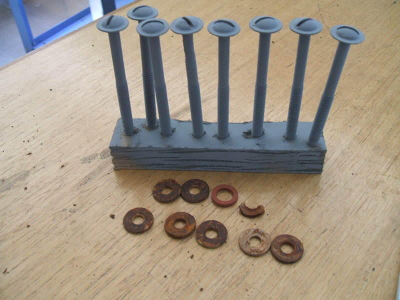
Cabinet top screws cleaned and sprayed with galvanising paint. New fibre washers were obtained.
8.1 Reattaching the cabinet top plate.
After some thought it was decided not to install a low side Schrader
valve. Firstly, Schrader valves do not make a perfect seal as experienced
by anyone who uses pneumatic tyres. The neoprene seal could deteriorate
over time. Secondly, a Schrader valve works better under pressure to hold
the seal against the valve core body. On the low side of a CA Monitor Top
where there is a vacuum, the valve would rely on spring pressure alone
for sealing.
Thirdly, it was completely unnecessary and just another potential point
for leakage. When the unit is connected to the vacuum pump, flow will be
enabled from the low side because the check valve is operating in the direction
of flow. As the compressor is a rotary vane type relying on centrifugal
force for the vane to cylinder wall seal, it follows that with the compressor
off, gas can flow past. Thus, it is possible to vacuum out the low side
through the high side charge valve.
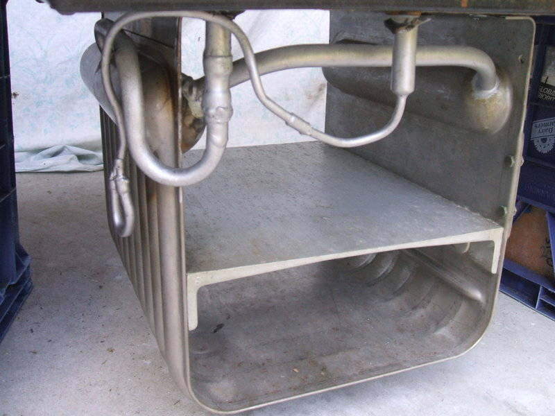
With the top plate temporarily in position, the length of the low side
joiner required was measured up. (I had cut off some of the evaporator
tubing to allow for the T piece). A piece of ½ tube was then belled
out at the ends with a swaging tool so that it could slip over the severed
ends. If a swaging tool was not available, a commercially made ½
joiner could have been used.
To minimise heating around the low side grommet in the top plate, the
joiner was first soldered to the compressor tube. Then the top plate was
slid over. Forcing the join through the grommet was awkward, but possible.
The cabinet top was then screwed down making sure the insulation was in
its correct place. The cabinet top plate screws had all been cleaned and
sprayed with galvanising paint prior, and one of the fibre washers required
replacement.
Cabinet top screws cleaned and sprayed with galvanising paint. New
fibre washers were obtained.
Soldering the low side evaporator connection was difficult. In fact,
MAPP gas was insufficient, and I had to use an oxy acetylene torch on a
low setting. The reason for this is that the original compressor to evaporator
join is a slip joint; i.e., the evaporator tube is slipped inside the compressor
tube before brazing.
This results in double the thickness of copper where I cut the join.
A wet rag was wrapped around the tube near the grommet to minimise
heat damage.
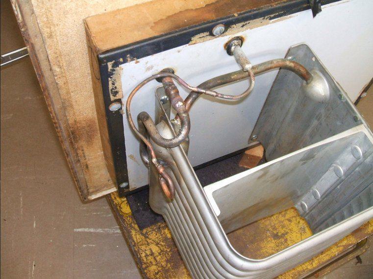
Cabinet top back together and system now sealed.
In comparison, the high side reconnection was quite straightforward.
The damaged high side tube at the evaporator connection was replaced with
a new length, bent to the original shape, and joined again by belling out
the ends with a swaging tool.
The system was now sealed.
9.1 Cleaning out the system.
Because of the contaminants in the system; e.g., air, moisture, oxide
from the soldering etc, it is necessary to clean it out before refilling
with refrigerant. It is also an opportune time to check for leaks.
First, the system is evacuated. This normally means vacuuming to 29
of mercury (Hg). When the system is under vacuum, the moisture boils off
and is sucked out. I used a digital vacuum meter (vacrometer) to give a
more accurate indication of the process. Additionally, I heated the compressor
and condenser with a heat gun. This process took about an hour.
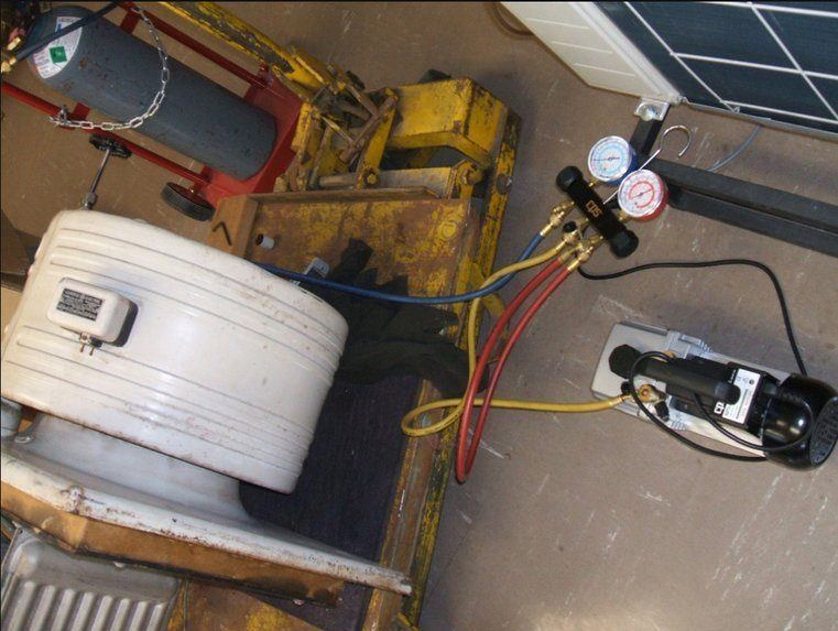
Placing the unit under vacuum prior to refilling with nitrogen.
Next, I refilled with nitrogen up to 30psi. A detergent solution was
then applied to all the soldered joins to check for leaks. The unit was
left alone for a week and checked again for leaks.
Finally, the nitrogen was slowly discharged, so as not to blow any
oil out.
9.2 Evacuating the system.
With the cooling unit in a warm room, the oil heater in the crankcase
was warmed up for a day. The evacuation began as before. A heat gun was
waved over the compressor, condenser, and evaporator until they were quite
warm to the touch (about 50C). The vacuum pump was run for an hour after
this. Vacuum achieved was 29.8.
About a week later, further vacuuming was done. This was to remove
any further contaminants that had not left the system previously. The oil
heater had been left running all this time to again help with evaporating
contaminants. It was observed that there had been no loss of vacuum in
the intervening time, so I was confident enough it was ready for refilling.
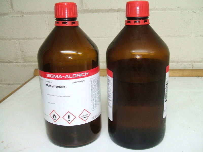
10.1 Methyl Formate bottles.
After some trepidation of not knowing what to expect, I opened the
first bottle. Under the screw on plastic lid is what Sigma Aldrich call
a sure seal top. It is just like a crimp on bottle top as used with soft
drinks. However, there is a hole in the centre, exposing the Teflon seal
beneath. This is intended for syringe use where a needle can pierce the
seal without allowing air in. But, as the Monitor Top does not need to
be worked on in hospital grade conditions, this is ignored and the top
removed with a bottle opener. The screw on lid does have its own seal,
but I did reuse the other seal just in case.
One bottle and part of another were required.
I could not really detect any smell and there was no pressure. On this point, the bottles had been refrigerated, given the 32C boiling temperature, prior to opening. This is quite important, and it would be unwise to open the bottles on a hot day. Methyl Formate is very flammable so the usual precautions have to be taken. Having said that, provided one takes sensible precautions; i.e. use it on a cool day, keep ignition sources away, and provide reasonable ventilation (fan and open windows sufficient), the liquid is quite docile. In fact, handling paint thinners is more obnoxious in comparison.
10.2 How to get the Methyl Formate
in.
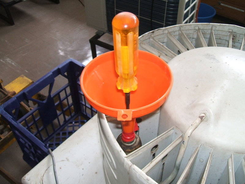
As the Methyl Formate is liquid at atmospheric pressure, it is simply
poured from the bottle, as one would do with a drink. To get it into the
cooling unit, I adapted a funnel to be a tight fit over the charge valve.
The idea would be that the funnel would be filled, and then the valve opened
slightly so the vacuum would suck it in. It would be necessary to always
keep the funnel nozzle full so as not to let air in. I found a clean plastic
funnel with a nozzle of slightly less diameter than the charge valve, and
gradually cut off the nozzle in very short increments until it was a good
push fit. Do not make it too tight or it will split. Just in case of leakage,
I wrapped insulation tape around the join.
With the Bristol key inserted, it was ready to refill.
The CA is very easy to refill, this being done at atmospheric pressure.
10.3 Refilling.
The Monitor Top labels are quite informative about the cooling units;
the CA-2 requiring 2.75lbs of Methyl Formate. To determine how much goes
in, refrigeration scales are used. Unlike normal scales, these not only
have superior accuracy, but can be zeroed with full weight on them.
With one bottle of Methyl Formate on (weighing 3.655lbs), the
scales are zeroed. As the bottle is gradually emptied the scales will show
an increase in weight by the amount that has left the bottle. I used a
beaker of water first to familiarise myself with how the scales operated.
It only took about 15 minutes to do the refilling. The first bottle
was emptied (2.215 lbs of Methyl Formate) and part of the second (0.535
lbs). Given that the specific gravity of Methyl Formate is not hugely different
to water, I had estimated around 1.2 litres.
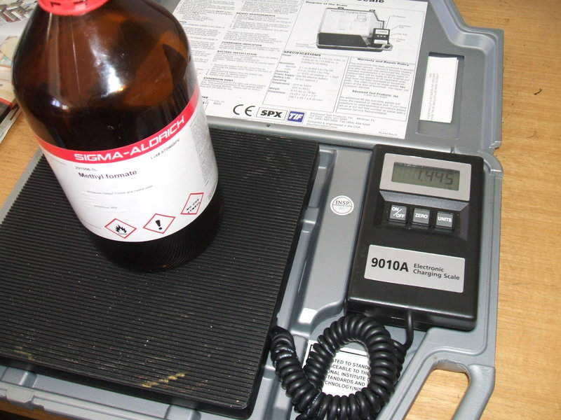
Refrigeration scales are used to weigh the amount of methyl formate
to pour into the cooling unit.
After the last lot had gone in, I left the remnants in the funnel nozzle
to evaporate overnight. It did not react with the plastic, suggesting the
solvent action is not as strong as some chemicals.
There was no odour present while refilling, and I did not take any
precautions handling it, apart from the obvious one of making sure there
were no ignition sources nearby and the room was ventilated. While some
did get on my hands, I simply washed it off afterwards in the normal way.
10.4 Starting the cooling unit.
Immediately after the 2.75lbs of Methyl Formate had gone in, I started
the compressor. Within about 30 seconds the evaporator was cooling, and
in a few minutes condensation was appearing. Apparently, all had gone to
plan and it was basically working. On the following day, I ran the unit
for about 30 mins, and got a good frost line up to the tops of the header
tanks. However, the frost line then started to drop, more so on the right
side (where the high and low side connections are).
Correct frost pattern formed on evaporator.
10.5 Purging and clearing the blockage.
I assumed that the deteriorating performance was due to non condensables
being released. Throughout the first operation, one could hear the pressure
building up and being released in the evaporator, presumably as the blockage
had started to dissolve and break off.
A power meter is a very useful device, and the fluctuation in power
consumption was clearly evident as this happened. When the cooling unit
had been operating properly, consumption was around 220 240W. As the
frost line dropped, the bottom half of the condenser cooled back to room
temperature, as did the float chamber. Power consumption went up; often
to 330W or more. A metallic rattling was also heard from the compressor
during periods of high power consumption.
Following the instructions in the CA repair literature, the cooling unit was purged. The procedure is to warm up the cooling unit so the high side pressure is positive. Placing oil in the charge valve will show if the pressure is positive or negative when the valve is cracked slightly. Bubbles going out shows purging can commence.
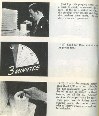
Excerpt from the CA service literature explaining the purging procedure.
Eventually, the Methyl Formate did reach the charge valve. It was evident
by the smell of something that wasnt there before, but also droplets
were reacting with the oil. At this point, purging was complete and the
valve was closed. Although the bottom of the condenser had warmed up, the
float chamber had not. Given that it was known refrigerant was now in the
float chamber, it had to be a blockage; the needle and seat being the likely
place.
GE did make an electromagnet for lifting the float from outside the
chamber just for clearing stuck floats. As such a thing would be now impossible
to obtain, I attached a rare earth magnet to the side of the float chamber.
Then I lifted the cooling unit a few inches off its temporary supports
and dropped it to shake the float loose.
Upon starting the compressor, there sounded like a good flow through
the evaporator. The high frost line returned, power consumption stabilised,
and the float chamber warmed up. It and the condenser reached 40 degrees
C.
As part of the high side tube runs around the cabinet top for additional
condenser area, this also warmed up. Further operation resulted in further
blockages appearing, but with less and less frequency and severity. It
would appear it is simply necessary to run the unit long enough for the
entire blockage to dissolve. At this point it was considered the cooling
unit was ready to place on the cabinet, so presenting it with normal operating
conditions.
11.1 Observations on the CAs operation.
Running the compressor for half an hour each day over a couple of weeks
revealed what the operating conditions are when everything is working properly.
The frost line level on the evaporator right side (where the high
and low side tubes connect) is the most revealing clue to correct operation.
If something is not optimum it falls before the left side does.
The float chamber should be the same temperature as the condenser
which should also be even from top to bottom. Typically this may be around
40 degrees C.
A high rate of flow of Methyl Formate should be audible through the
float chamber, perhaps enough to lightly rattle the float. This is best
heard with the unit out of the cabinet and ones ear against the cardboard
surround adjacent to the float.
Power consumption, with the heater (14W) and step down transformer
for 240V operation(19W), is 200-240W when operating correctly.
11.2 Possible problems.
High power consumption (>300W), and/or the compressor stalled when
starting indicates excessive compressor load from either too much non condensable
gas build up, or a blockage (most likely the float valve). This is provided
the motor, wiring, or start relay is not the cause of a stalled condition.
The compressor may also be stalled after transportation because of
Methyl Formate entering the compressor in liquid form. In this case, power
up the crankcase heater for several hours before operating.
A loud metallic rattling sound from the compressor is caused by the
above due to excessive load. A quieter rattling sound with low power consumption
(<220W) indicates lack of refrigerant flow.
If the top of the condenser is warm but the bottom is not, there
is a blockage, or non condensable gas build up. The float valve will not
be warm in this condition.
If the condenser is evenly warm, but the float chamber is not warm,
there is a blockage or non condensable gas build up.
If the non condensables have been purged, then the above are caused
by blockage.
If there is a hissing sound from the float chamber when the compressor
is turned off, the float valve is not seating correctly; either due to
foreign particles or needle and seat wear.
Low frost line indicates inadequate refrigerant. If no Methyl Formate
has been lost, the oil heater could be inoperative starving the unit of
the full amount required. Inadequate refrigerant to the evaporator is also
due to a blockage or non condensable gases.
12.1 Cosmetic Restoration.
As obtained, the fridge was in good condition for its age, but the
appearance could be improved upon.
12.2 Cabinet.
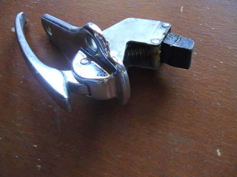
This was in good condition with hinges, latch, and foot pedal all functional
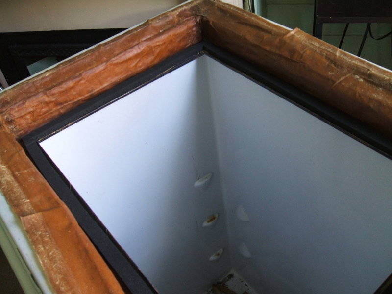
without any noticeable wear. The porcelain interior is in excellent condition.
The door seal had been replaced and appeared to function correctly. The
insulation and cabinet light wiring was all in good condition. An Australian
made 15W 120V bulb present in the light socket still had an intact filament.
Things that needed attention were:
Synthetic enamel finish worn away in some spots, and faded all over.
Rubber seals at top of cabinet had deteriorated.
No-ox-id seal at cabinet top to be straightened out and tears filled
with silicone.
Shelves have been painted and have some surface rust. One shelf is
missing.
Rubber pads for cabinet feet have hardened. Reproductions are available
and were purchased.
Door seal was not original and had an imperfect fit.
First thing to do was clean the cabinet with 600 grade wet and dry sand
paper. This improved appearance considerably, and had it not been for scratched
off enamel, the cabinet could almost be left as is.
One coat of primer was then applied; one 325g aerosol can required
for the cabinet and door. More would have been required had the cabinet
finish been in poorer condition.
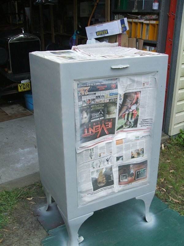
After one day, the cabinet was ready for the final coats. Here, I used
three coats of white appliance enamel. Approximately 3.5 350g aerosol cans
were used.
The top seal was replaced using 12 x 18mm Neoprene seal from Clark
Rubber. Due to condensation it is important to use a seal rated for contact
with water.
12.3 Door.
It is considerably easier to do this work with the door off the cabinet,
and this was painted separately. Note that the hinges are attached so that
the forces oppose. That is, the upper hinge pushes the door open while
the lower hinge tends to push it closed, but by a lesser amount. This is
so that when the pedal is used the door only springs open slightly.
Do not try to install the hinges so both spring outwards; the door will
not fully open and may be damaged if forced.
Again, one coat of primer and three coats of enamel were applied. The
hinges and latch were cleaned and polished with Brasso. The hinges were
lightly oiled, and the latch greased on the moving surfaces.
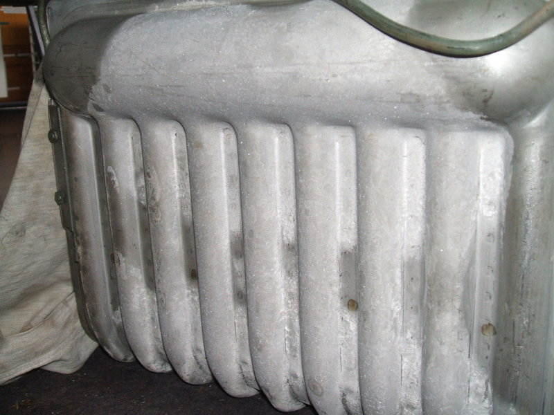
12.4 Cooling unit.
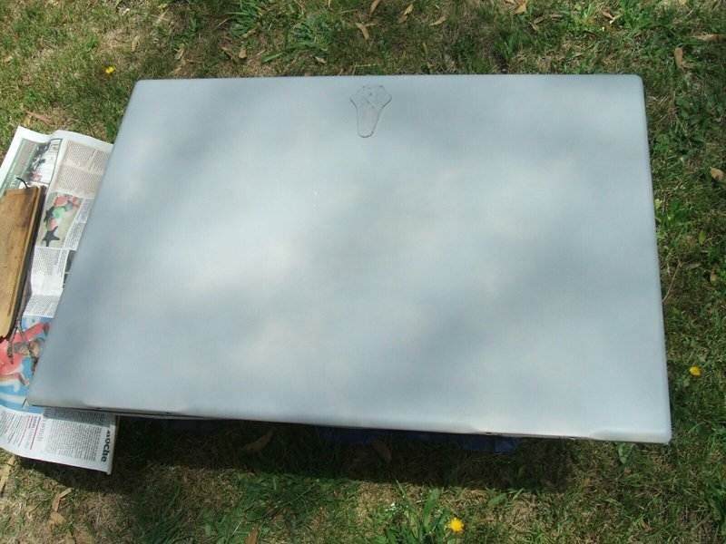
As per the rest of the fridge, the cooling unit was sanded and repainted.
For the whole cabinet and cooling unit, two cans of primer and four
of enamel were required.
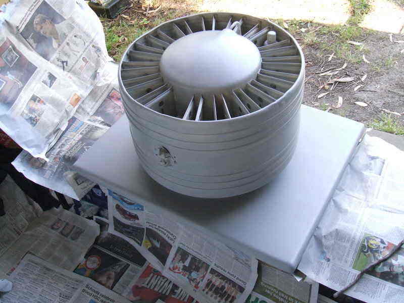
Cooling unit primed with one coat.
Cleaning between the fins was difficult, but as this was a cosmetic
restoration it was decided not to strive for perfection as at normal height
this area is not visible.
The seal around the perimeter was replaced with the same 12 x 18mm
Neoprene as used on the cabinet.
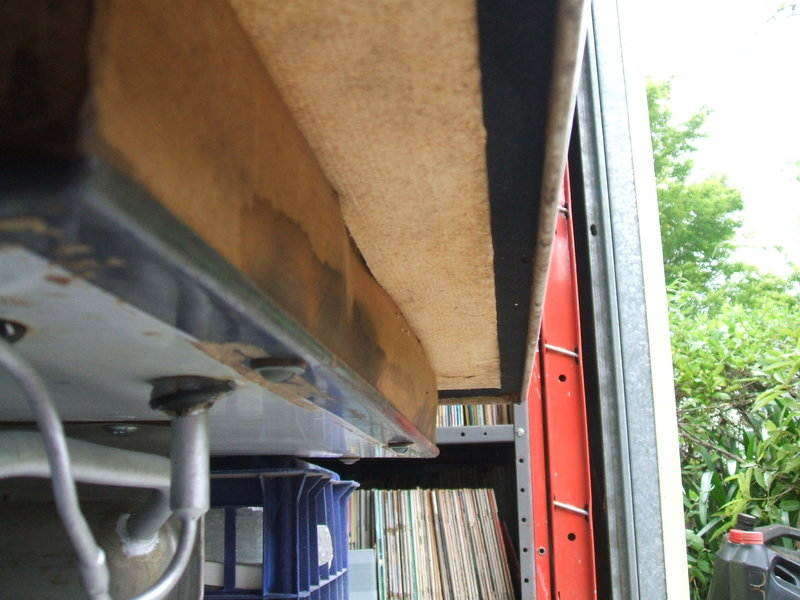
Top seal replaced by 12x18mm Neoprene.
Finally, the plumbing was painted. Given the difficulty of masking the required areas, the paint was sprayed into a small container and then brushed on. I used silver epoxy paint.