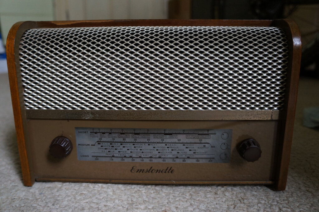
This English made mantel radio had been the victim of bodgie work and contained design faults. Notice no dial pointer - we'll get to that later.
This English made mantel radio had been the victim of bodgie work
and contained design faults. Notice no dial pointer - we'll get to that
later.
At the August 2022 HRSA meeting, this Emstonette
mantel radio was thrust into my hands, with the acknowledgment that I have
an affection for live chassis radios and televisions. Indeed, I must be
one of the few Australians that does like these sets. Seeing as the rest
of the world gets on with them without problems, I see no reason not to
either. They make a nice change to the conservative and predictable Australian
designs.
I had never heard of Emstonette before.
The only internet searches brought forth an ebay sale of one of the same
model as I had acquired, and the other was a radiomuseum mention of different
model with no real information.
On the back of the set, there is no model
number; only the address of the manufacturer. From the date code on the
speaker, it was made in the 5th week or 5th month of 1956.
.jpg)
Made by J&M Stone in London. There is no model number.
I had been told that the set was live chassis,
but there was an oddity, in that "there's a 6V6 in it". At first I thought
of the common design where 6.3V valves were heated by a transformer, and
the B+ was rectified mains. But then, that would preclude the DC operation
which the set is clearly labelled for. I didn't think too much about this
until I got home and opened it up.
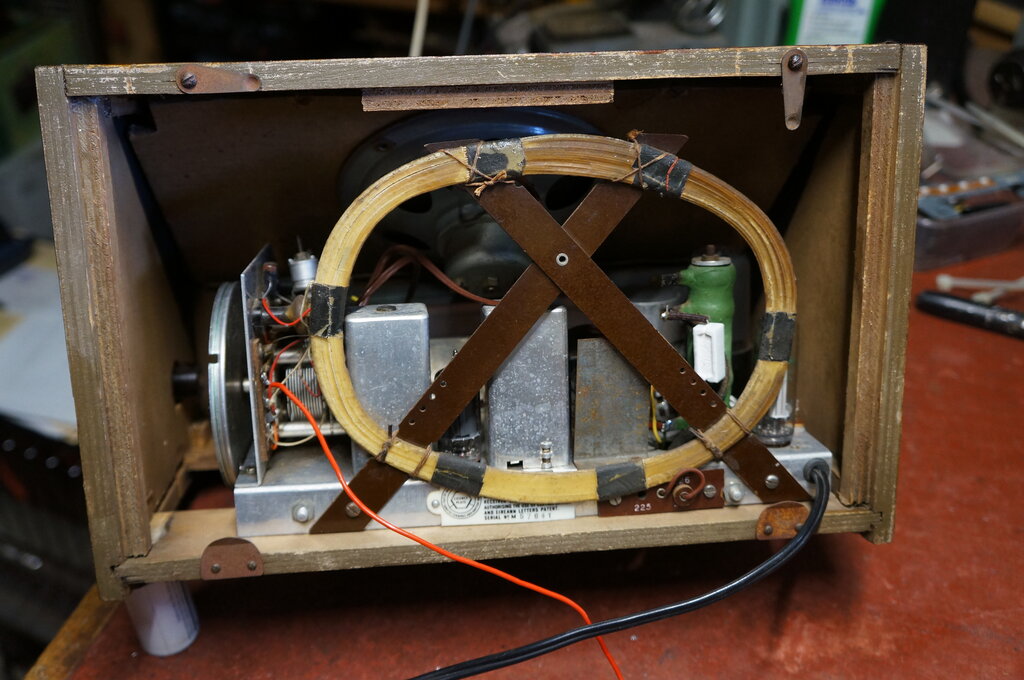
And what a bodge awaited me!
At this point, it's best to first describe the bodgie things which had been done to the set, then I'll describe the tidying up, and the getting it going parts of the exercise.
The Set of Bodge.
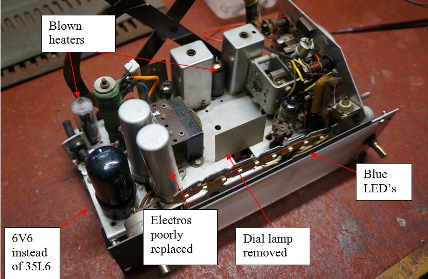
Starting at the top of the chassis, the
most obvious thing was the 6V6. It stuck out like dog's balls. Unless it
was to have its heater supplied with a transformer, or dare I say it, a
dropper capacitor, there is no way this valve could be used in this set.
The two can electrolytics were a pair
of Australian made Ducons. The original was obviously a dual capacitor
in a single can. There's nothing wrong of course in using separate capacitors
as a replacement - except one had been mounted with only one screw, and
the position of the terminals was such that a short circuit was imminent.
There was an array of LED's behind the dial, supported on a homemade bracket. Someone had gone to a lot of effort to avoid replacing the original dial lamp.
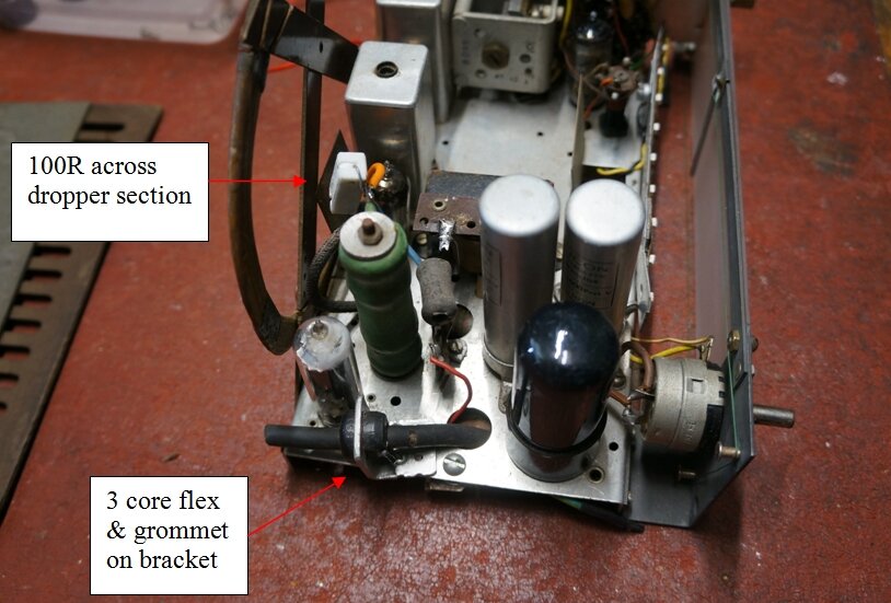
One of the dropper sections had been bridged out with a 100R 5W resistor. There's nothing wrong with that, assuming the resistor is the correct value. Our would be restorer obviously didn't like the original twin flex mains cable. Instead, heavy duty three core flex had been fitted. Since this was too thick to go through the original entry hole in the chassis, an aluminium bracket had been made with a cord grip grommet to secure the cable. The earth wire was covered in heatshrink. The aluminium bracket was attached to the chassis with two bolts and a rivet.
Seeing the 6V6 installed, and that the
35W4 was white topped, suspicion fell on the other valve heaters, and so
all were tested. The 35W4 was not surprisingly open circuit, but so was
the 12BA6.
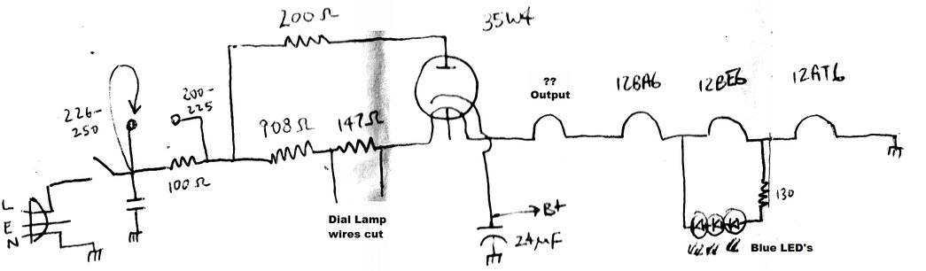
Curious how the LED's might have been
powered, I traced their connection to being across the 12BE6 heater. An
obvious problem here is that the LED current will subtract from the 12BE6
heater current. Clearly, our would-be restorer had a minimal grasp of electrical
theory.
Furthermore, it was assumed the LED's
would be happy being fed with AC, since there was no rectifier of any kind.
Something else to ponder is that if the 12BE6 should be removed, or its
heater goes open circuit, the LED's will be subjected to the full 240V
supply.
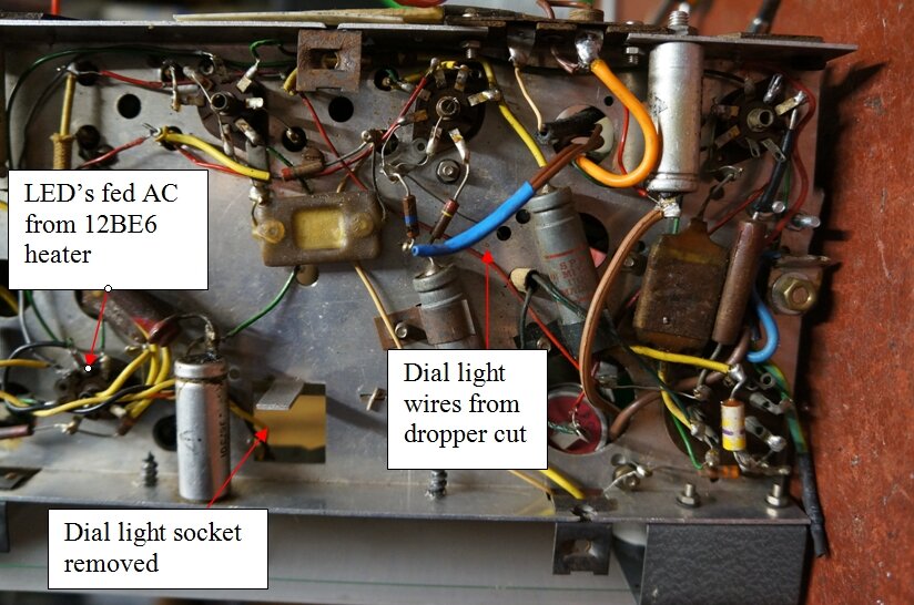
Knowing the original dial lamp would have been part of the heater string, I traced out where it might have been. Actually, it stood out quite clearly with a section of figure 8 wire running towards where the socket was once mounted. The wire had been cut and covered in blue heatshrink.
The dial pointer seemed a bit strange, since it was on the reverse side of the diffuser panel, and not visible from the dial. Situated thus, all it would be able to do is cast a vague shadow. A closer look revealed that the dial pointer was home made, constructed from a cut off nail or rivet, and a piece cut from a tin can.
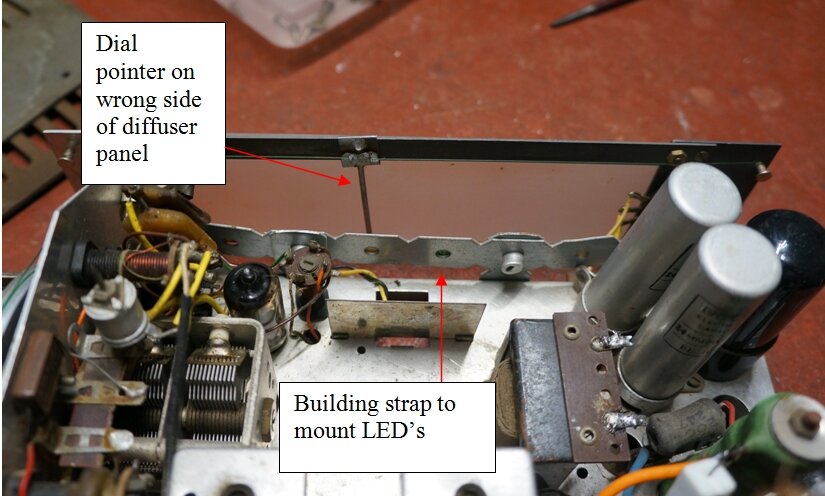
The dial cord itself had been restrung with fishing line. This can be a suitable replacement for dial cord, but the way it was done here wasn't very professional. An extra spring had been added on the dial drum since both ends of the cord came in separate entries, rather than a single entry point with a common spring. The cord was slipping on the pulley, so would have to be re-strung anyway.
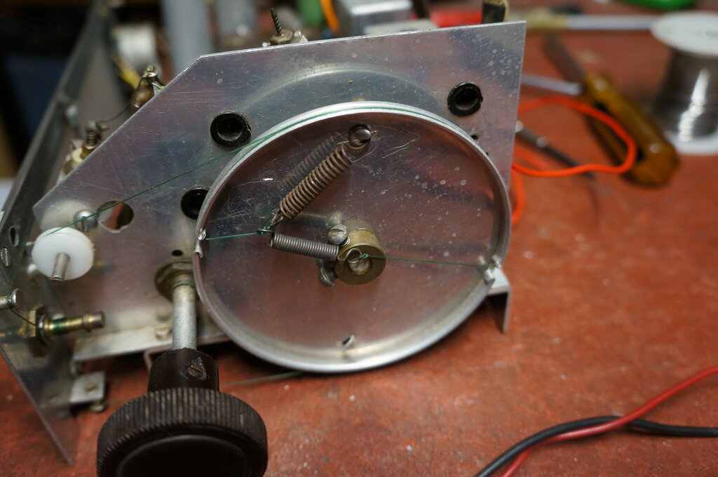
Dial cord should come in at one point on the drum and use a common
spring.
Original cable entry grommet at top left.
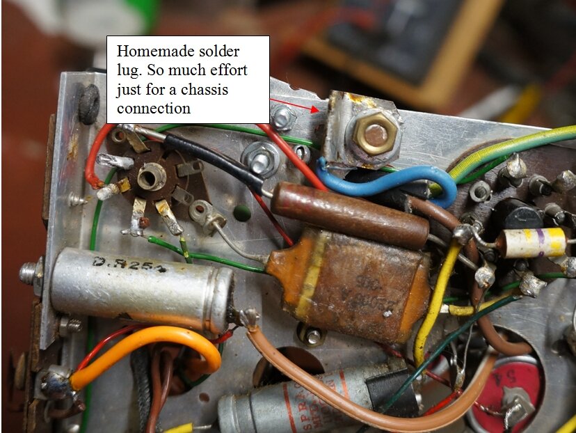
The same kind of tin had been used to make a solder lug to attach the neutral mains wire to the chassis. It was secured with a bolt, two nuts and a washer. A lot of work, when the original neutral solder lug was a couple of inches away.
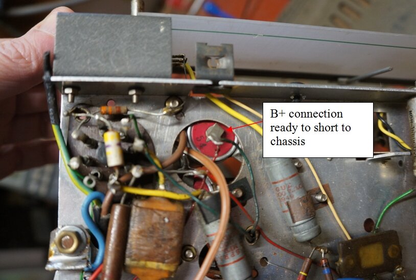
B+ electro close to shorting out. Original mains neutral connection
is the solder lug at the top left of the octal socket.
Also under the chassis, looking at the
replacement can electros, one of them was less than a millimetre away from
shorting to the chassis. All the more likely, being secured by only one
screw.
Just for fun, I powered up the LED's with
12V DC, and was surprised to see they were all blue. The LED's were in
three flexible strips on three, each with their own 130 ohm resistor. These
had been attached to the building strap with silicone. Interestingly, only
one of the strips had been connected.
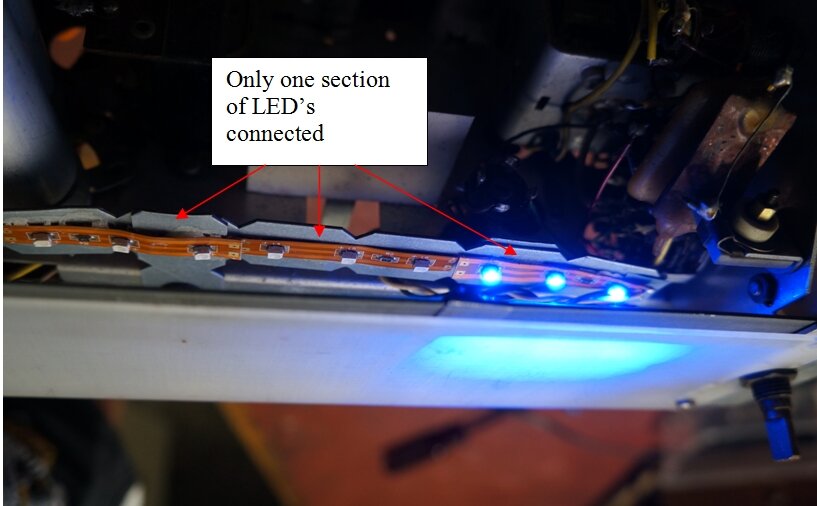
This would have to be the ugliest attempt at dial lighting I have ever seen. In fact, it was quite nauseating to look at. Our would be restorer had only connected three out of the nine LED's.
As found when I got the set.
Looking at the valve types, it was obviously
using a 150mA heater string. Essentially, it was what has become known
as an "All American 5", but adapted for a 200-250V mains supply. These
valve types were also made in the U.K. by Brimar, which was the valve division
of STC (Standard Telephones & Cables).
For octal 150mA heater output valves,
there's really only a choice of two types, which are the 50L6 and 35L6.
The other common series heater octal output valve, the 25L6 has a 300mA
heater, so it obviously wouldn't be that.
Out of curiosity, I fed the 6V6 heater
with 150mA, and found only about one volt across it. So, the radio wouldn't
have worked at all, even before the 35W4 and 12BA6 burned out.
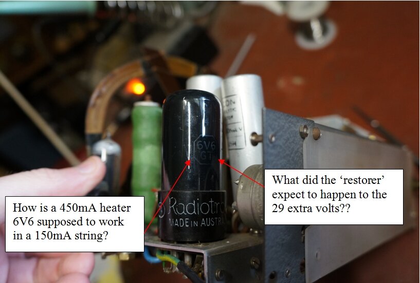
At 150mA, the 6V6 cannot function at all.
The dropper resistor has three sections. The first section is only in circuit for 226-250V mains. It was open circuit and had been bridged with a 100R 5W resistor. The main section measured 908R, and the final section used for the dial lamp shunt measured 147R. There are no markings on the resistor, so the measurements can be assumed to be close to the manufactured values. Wirewound resistors don't drift in value; it's either correct or open circuit.
The dial lamp voltage is negligible in the overall scheme of things, so the 147R section need not be considered in our next calculation. The voltage drop across the 908R section will be 0.15 x 908 = 136.2V.
Now, lets assume a 50L6 output valve. The
total heater voltage will be 12.6 + 12.6 + 12.6 + 50 + 35 = 122.8V.
Assuming a 35L6 instead, the total will
be 12.6 + 12.6 + 12.6 + 35 + 35 = 107.8V.
If we use a 50L6, the mains end of the
908R will need to be 136.2 + 122.8 = 259V.
If we use a 35L6, the mains end of the
908R will need to be 136.2 + 107.8 = 244V
Given a choice, the output valve will have
to be a 35L6. Even so, there's a problem and we discover a design fault.
With only the 908R section in circuit, there is no way the receiver can
work optimally on 200-225V mains. In fact, it's slightly worse, since we've
not included the dial lamp drop (say, 5V). Assuming a mean supply voltage
for this setting of 212.5V, the dropper resistor should be (212.5 - 5 -
107.8) / 0.15 = 665 ohms.
This is very puzzling since the heaters
will always be under run.
The situation is worsened on the 226-250V
setting, since there's more resistance introduced into the circuit. Not
only that, this extra resistance feeds the heaters, as well as the
B+. In this situation, to get anything like the correct heater current
with present day 240V mains, the setting should be put on to 200-225V.
What is even more horrifying is that when our would-be restorer had removed the original dial lamp, the 147R section was introduced into the heater string. And since he had included the 100R replacement for the open dropper section, the total heater dropper resistor was 100 + 908 + 147 = 1155R. For proper heating of the valves, the mains would have to be 281V! (Actually, slightly more, because of the B+ current through the 100R). Clearly, a lack of familiarity with ohms law was evident here.
Dial Lamp.
What should the dial lamp voltage and
current be? It could actually be one of many choices, since British and
European series heater sets were renowned for using obscure bulbs for their
dial lights.
At first glance, one might assume it's
simply a matter of connecting a 150mA dial lamp, of any voltage up to about
12 or so, in series with the valves. The problem is the bulb will be blown
open circuit when the set is first switched on. The resistance of a tungsten
filament when cold is much lower than when it at operating temperature,
and so there is a considerable surge current. Valve heaters run at a lower
temperature (red hot), than do light bulbs (white hot). So, the valves
come up to temperature much more slowly than does the dial lamp. The dial
lamp cops the extra voltage and quickly burns out.
One way around this problem is to install
a suitable thermistor in series with the heater string. The heater current
rises slowly enough so that the dial lamp is never overloaded. Indeed,
many designs did just this. The Howard
474 is one example.
Thermistors cost extra, so penny pinching
designs don't use them. Instead, a fixed shunt resistor is connected across
the dial lamp. This shunts enough of the cold switch-on current around
the dial lamp so that it isn't overloaded. The catch is, once the valves
have warmed up and settled down to drawing 150mA, the shunt resistor is
still shunting current away from the dial lamp. Thus, it runs at reduced
voltage (and brightness) for the remainder of the time the set is switched
on.
Similarly, using a higher power dial lamp
to absorb the switch on surge isn't the answer either, because it too will
be running at reduced current after warm up.
A scheme to improve upon this involves the use of the tapped heater of the 35W4. The dial lamp is shunted across a portion of the 35W4 heater, and is thus protected against the switch on surge. However, after warm up it still won't be at full brightness, because some power is always diverted to the heater. A clever trick does improve things, however. By arranging the circuit so that the AC supply to the rectifier plate is also passed through the dial lamp, its current is increased by that of the B+ after warm up. We're getting a bit ahead of things here, since this is not applicable to the way the 35W4 is used in the Emstonette, but you can learn more about it here.
The Emstonette uses the shunt resistor method of dial lamp supply. A dial lamp of greater than 150mA is pointless, since it will never run at full brightness, and will be worsened by the shunt resistor. The lesser the current is below 150mA, the more likely it will be overloaded at switch on. "Normal" dial lamps are 6.3V or 12.6V, with a few at 24-28V. The lower the shunt resistor, the better the surge protection, but also the dimmer the bulb when everything has warmed up. As you can probably see, the whole scheme is a compromise. One thing we do have fixed is the 147R shunt section, and that's what we have to work with. A good starting point is a 6.3V 150mA bulb. At 6.3V, 147R draws 43mA, so that gives us an allowable switch on surge of nearly 200mA.
I did try a 6.3V 150mA bulb, and it seems OK. The switch on surge voltage is up around 7.5V however, and operating voltage is 4V. Subsequent testing seemed to indicate a 12V 100mA bulb is also suitable; this starting at about 14V, and settling down to about 9V. Shunt zener diodes connected back to back are a possible option for eliminating the surge altogether.
Tracing the Circuit.
Since no circuit was available, I had
to trace my own. Apart from the complicated front end, with its peculiar
band switching, the rest of it was predictable and straightforward.
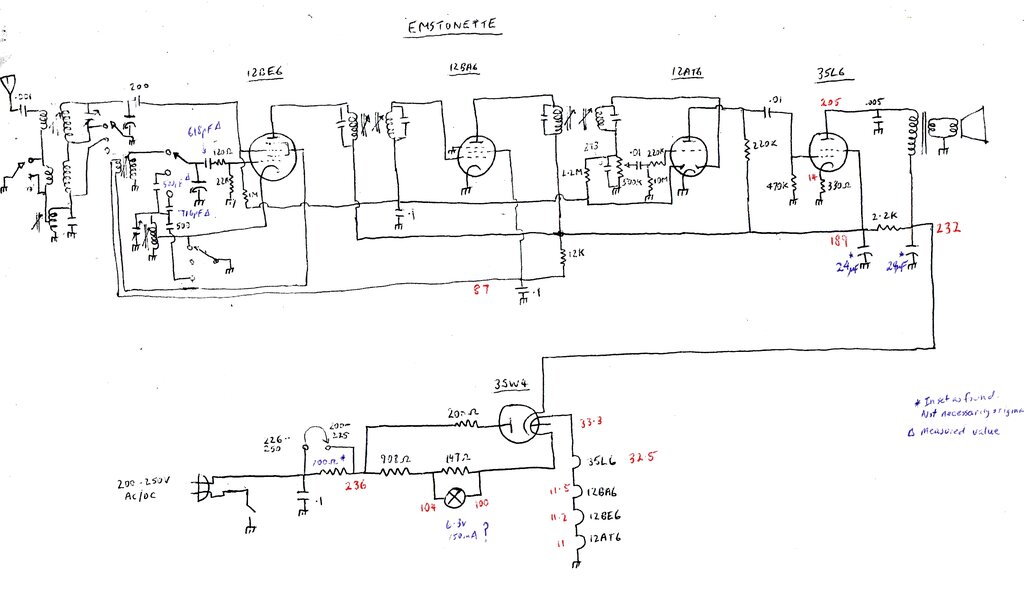
Circuit as manufactured. Voltages measured when first powered up.
Note the mains switch in the neutral is for the original circuit only.
Valve heater voltages marked are across the heaters, not to earth.
The first unusual thing is the aerial trimmer
is connected only across the SW aerial coil. How one is supposed to set
the tracking for MW and LW is unclear. Similarly, the local oscillator
trimmer is only in circuit for MW and LW.
Note that there's actually two separate
local oscillator circuits. The MW and LW bands use the normal tapped oscillator
coil in the cathode circuit, as is usual for the 12BE6. However, for SW,
feedback is via the screen grid and a separate winding.
Whilst tracing the circuit, I noticed
a capacitor lead pushed against the chassis where it shouldn't have been.
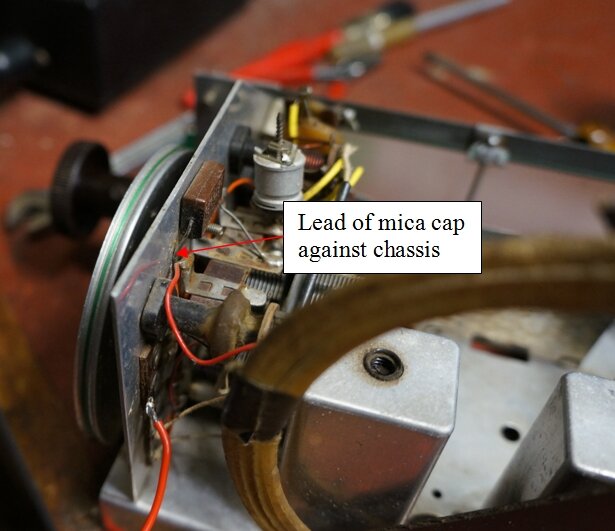
I doubt the set ever had good LW reception, with the lead of this
mica cap pressed against the chassis.
The 12BA6 IF amplifier has no cathode bias. Its only source of bias is therefore the AVC line, which will always develop a slight negative voltage because of noise, and additionally, the second diode plate of the 12AT6 is used to generate contact bias. This occurs because electron emission from the cathode builds up a negative charge on the diode plate. Of course, with a station tuned in, the AVC voltage will increase to several volts negative.
Another unusual design aspect is the very high grid stopper resistor (220k) for the 12AT6 triode. Normally, the 12AT6 does not require a grid stopper, but it appears they've used it to avoid using a plate bypass capacitor. Any residual RF from the detector via the volume control will be reduced by the low pass filter formed by the 220k and grid capacitance. Unfortunately, this is poor design because the grid impedance can never be less than 220k to earth, and is thus susceptible to hum.
The operating conditions of the 35L6 are questionable, since this valve was never designed for sets operating on 200-250V mains. This will be described in further detail later on.
Restoration Begins.
Now, to begin restoration. First thing
is the electrolytics. The original was a single can type with two sections.
If I didn't have anything suitable, I could re-use the two that came with
the set, by mounting them properly. I tested them and they were in excellent
condition.
As it happened, I did have a suitable
can electro, and even the mounting holes lined up. What I found was a dual
40uF 350V type. I will never know what the original values were, but 40uF
is the maximum limit for the 35W4, so I had no hesitation in using it.
Furthermore, the surge limiting resistor in this set (200R) is much greater
that specified, so peak current will be even less.
With this installed, and the LED's gone,
the chassis was looking much neater.
Next was the mains cable. The original
twin flex was of a very small gauge, rather like speaker wire, so the entry
hole needed enlargement to take normal twin flex. The original grommet
needed replacing anyway since it had deteriorated.
I am not keen on running a set with no
fuse; especially one with a capacitor across the mains, so I installed
a 3AG fuseholder on the chassis over all the holes where the cord clamp
grommet had been attached. This type of fuse holder has nothing to stop
it swivelling around and shorting, so I had to make a suitably shaped aluminium
bracket to locate it. I chose a 250mA fuse, since that would be about the
lowest to cope with the switch on surge. The actual set current would be
around 200mA.
The bodgie neutral connection and its bolt
had to go, and in locating the original neutral connection I discovered
that as originally built, the power switch was in the neutral line. A piece
of wire had run from the chassis to the switch on the volume control, and
the remnants were still there after being cut off. It's very common to
have the switch in the neutral in series heater sets of U.S. design. The
reason for so doing goes back to the use of line cord resistors. Ideally,
one should switch both the heater resistor, and the full supply going to
the rectifier. This requires a double pole switch. Instead, just by switching
the neutral, only a single pole type is required, and the cost is lowered.
Unfortunately, switching the neutral ensures
the chassis is guaranteed to be live, either when the set is off, or when
it is on.
Despite his other errors, our would-be
restorer had actually done the right thing, and put the switch in the live
side. I retained this, connecting the neutral to chassis, and the live
to the fuse holder, thence to the switch, and then to the rectifier and
heater dropper.
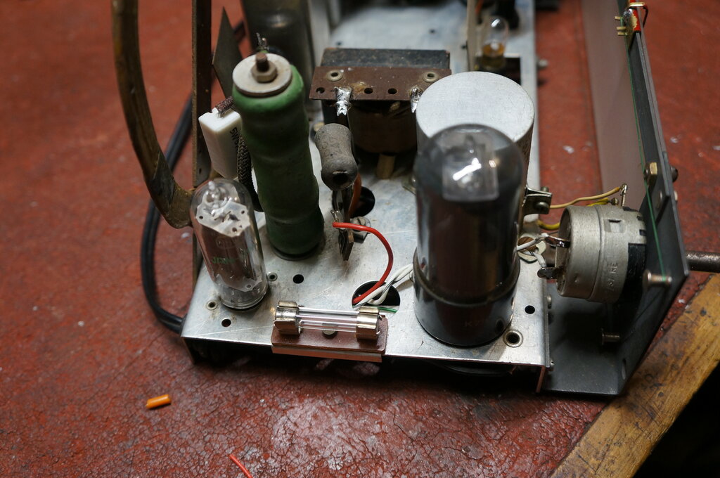
Figure 8 cable replaced, new 35W4 and 35L6, and fuse installed.
At this point, the set was almost ready for its initial test. One thing that needed to be done first was to replace the .01uF grid coupler for the 35L6. It tested at 40M leakage at 500V. Also, the 470k grid resistor had risen to over 600k, so it too was replaced. Especially for valves like 35L6 which are prone to grid emission, the grid resistor needs to be as low as possible. The data specifies a maximum of 500k when cathode bias is used.
With a new 35L6, 12BA6, and 35W4 installed, the set was powered up with a variac, just in case there was some nasty surprise lurking in the heater circuit. There wasn't, and all the valves warmed up normally, with the dial lamp operating satisfactorily. After selecting MW, it was possible to tune in stations. The pickup on the loop aerial alone didn't seem to be that great, but the set was basically functional.
Dial Pointer.
The tuning was a pain, with no dial pointer
and a slipping dial pulley, so that was attended to next. I made up a new
pointer out of brass, and painted it red. With slight adjustment, it slid
across the dial nicely. The dial needed to be re-strung, and initially
I tried proper dial cord. Unfortunately, the lack of proper pulleys around
the dial caused too much friction and was not usable. So, I went back to
the fishing line. An extra turn on the drive pulley fixed the slipping.
The extra spring was removed, and both ends of the dial cord brought through
the same entry point on the dial drum. At last we had proper tuning control,
and a pointer that looked correct.
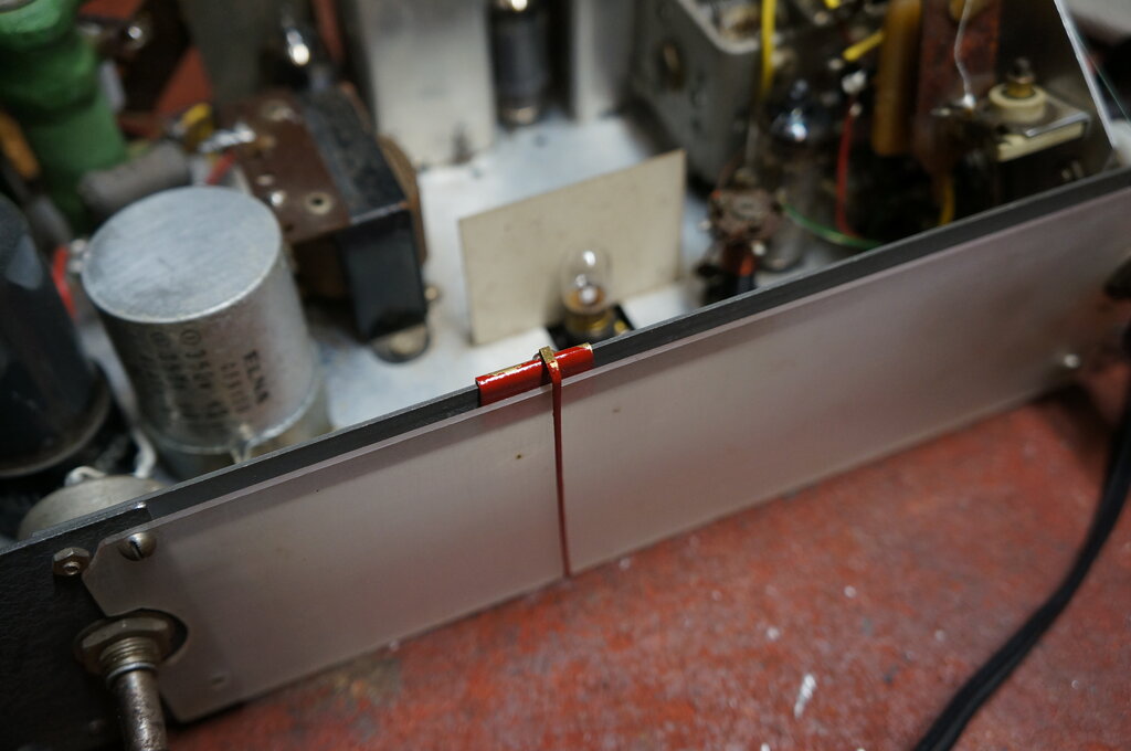
New dial pointer. Note also the can electrolytic, and dial lamp.
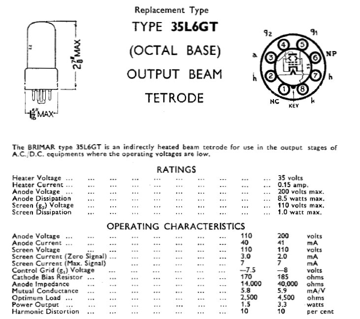
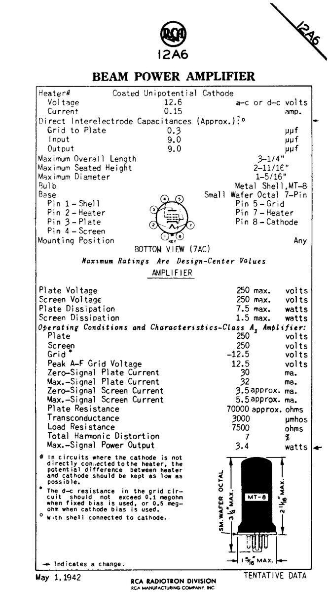
The 35L6.
The 35L6 beam tetrode was designed in
the U.S. for series heater sets operating on their 110-120V mains supply.
This is evident in the data:
These U.S. designed valves could be used
in 200-250V receivers in a number of ways. One, which is the crudest of
all, was to simply operate a 120V set through a dropping resistor; either
on the chassis or as a line cord resistor. The most serious objection to
this scheme is that a common resistor means that the heater voltage is
dependent on the B+ current consumption. With a 150mA heater current, a
B+ current of 50-60mA is not insignificant! What happens is that the heaters
are overloaded until the set warms up and B+ current is drawn.
Alternatively, if the resistor is chosen
for correct heater current to start with, once the set warms up the heaters
are under-run. Calculating the resistor value is also difficult because
B+ current is drawn only on every half cycle, due to the half wave rectification.
And even then, current is only drawn near the peak. It's a cheap nasty
bodge, unfortunately all too often seen.
The proper way is to feed the heaters and B+ through separate resistors. This way, the variation in B+ current does not affect the heater string, before and after warm up.
Looking at the 35L6 data, we can see the screen voltage is a maximum of 110V. The plate is also 110V, but up to 200V is allowed for. With screen grid valves, the plate current remains largely constant over a wide voltage range, provided the screen grid voltage is fixed. Indeed, this constant current plate characteristic is made use of in some specialised circuits. The important point to watch out for is that at higher plate voltages, the dissipation is not exceeded.
So, what have Emstonette done to use the
35L6 in their set? The plate voltage is within ratings at 205 - 14 = 191V.
The problem is the screen voltage is exceeded at 187 - 14 = 173V. It appears
they have got the actual dissipation down by increasing the bias (-14V
instead of -8V). As it is, both the screen grid and plate dissipation are
within ratings, as is the cathode current (43mA). The valve won't fail
from overheating used this way, but I am not keen on the increased screen
voltage. The question also must be asked about overbiassing the valve,
and perhaps introducing more distortion.
Since the original 35L6 was not present,
I have no idea if it failed because of the increased screen voltage. 35L6's
are not exactly a dime a dozen in Australia, where series heater sets are
a rarity, and are now expensive to buy because of increased postage costs
from the U.S., it was best to do it correctly.
The easiest, and most obvious way is to
change the 2.2k filter resistor to reduce the secondary B+ rail to 110V.
This would also allow the bias to be reduced to the correct level. It all
worked out very well, with the resistor changed to 4.7k. The bias resistor
was reduced to 180R.
A further modification was necessary now
that the 187V supply was reduced, and that was to remove the 12k resistor
feeding the IF and converter screen grids. If left as original, this rail
was now about 62V. While not a problem, it's better to run it at 110V instead,
with the improvement in gain and volume this provides.
In fact, the radio was now working a lot better than it had been previously. There had been signs of instability, in that the IF channel was on the verge of oscillation. With the unshielded 12BA6 right next to the loop aerial this would have been part of the problem. Also, note there was no RF bypass on the 187V rail; just the electrolytic. Cheap sets omit the RF bypass because the electrolytics will be good enough for this function when the set is new. But now, with the 12k removed and shorted out, we had the 0.1uF across the B+. A further improvement in stability came from reducing the 187V to 110V. With less audio being lost across the unbypassed cathode bias resistor of the 35L6, its gain was increased slightly.
Heater String.
That Emstonette had miscalculated the
heater dropper was certainly borne out in practice. Even with the voltage
selector on the 200-225V position, the heater dropper resistance was still
too high. As you can see from the heater voltages on the circuit above,
all were low. In particular, the 12AT6 and 12BE6 were under-run by more
than 10%. The 12BE6 efficiency, particularly on SW would be reduced, but
more problematic is the cathode poisoning which occurs when valves are
run at reduced heater voltage, when normal cathode current is drawn.
At this point it must be mentioned that series heater valves are designed for a specific current. The voltage is nominal only. So, when testing for the appropriate dropper, use an ammeter, not a voltmeter. The heater voltages should only be used as a guide.
What to do? Since the dropper resistor
was fixed with no variable tapping, the only way to restore correct heater
current would be to parallel another resistor across it. At the same time,
I decided to tidy things up a bit. Since the mains is 240V, to correctly
use the voltage selector entails the common 100R section. As I've just
pointed out this is poor practice. True, I could move the B+ surge resistor
to the mains side of the 100R to eliminate this.
But, I decided to get rid of it all together.
As it was, that section of the dropper was already open, so it was a good
reason to remove the tacked on 100R, and design the heater circuit for
240V, since this has been standard throughout Australia for many decades.
To do this, I used a variable DC power
supply (BWD 215). Current measurements on DC are more accurate than AC,
and there's no need to worry about waveform calibration. The 215 can supply
up to 200mA, and is regulated. The set was powered up, but with the polarity
reversed so the B+ current would not be drawn; only the heaters and dial
lamp.
The ideal parallel resistor was 8.2k,
which brought the heater current to exactly 150mA at 238V. Perfect!
The heater current limit to stay within
ratings is +/- 5%. This equates to 142.5mA to 157.5mA. The voltages were
measured over this range to produce the following results. The 6.3V 150mA
dial lamp and 147R shunt were in circuit, but are not part of the heater
voltage measurement.
| Heater Current | Total Heater Voltage | Mains Voltage |
| 142.5mA | 101.2 | 223 |
| 150mA | 109.8 | 238 |
| 157.5mA | 119 | 254 |
As we can see from the original circuit
with the 908R dropper, and with 236V mains, the total heater voltage was
100V. This is just under the acceptable minimum, and allows no leeway if
the voltage should drop further. With the dropper reduced to 817.5R, the
normal range of mains voltage is nicely accommodated.
As a matter of curiosity, the polarity
was then reversed and the set operated as it would on DC mains. Total current
consumption at 238V was 208mA. The B+ current is therefore 208 - 150 =
58mA. It was also interesting to observe the B+ supply voltages on DC.
B+1 was 206V and B+2 was 106V.
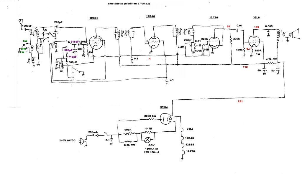
Circuit of the the modified Emstonette. Operating conditions are
now correct. Capacitors in purple were measured to determine value. Note
trimmer across the MW aerial coil.
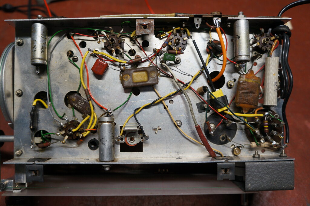
Under chassis after restoration complete.
The AVC filter condenser measured 50M leakage at 500V. Seeing as the only bias for the 12BA6 is developed across this condenser, and from a high resistance source, I felt it best to replace it with a polyester type. 50M leakage is acceptable, but the problem is if it gets much worse.
Finally, there was the alignment test.
SW was pretty poor - the receiver is insensitive on this band. No doubt,
the lack of a local oscillator trimmer doesn't help with the tracking with
the aerial coil. The local oscillator weakens and drops out around 6.5Mc/s.
Top frequency on SW is about 21.8Mc/s.
MW, despite the lack of an aerial trimmer,
wasn't too bad. However, I found that an aerial trimmer did improve things,
by about 3dB at a guess. About 2-3pF seemed about right, so a ceramic trimmer
was connected across the aerial coil and peaked up.
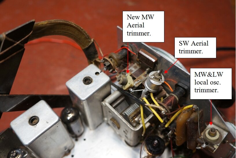
Poor design not to include an aerial trimmer for MW, so one was
installed.
That left LW. Tuning range is about 150Kc/s
to 300Kc/s. Since this shares the same L.O. trimmer as MW, all I did here
was check the adjustment of what appears to be a kind of loading coil,
in the earth return of the MW aerial coil. I just tuned to 200Kc/s and
found it was already peaked up.
There is nothing on LW in Australia, and
SW listening is pointless, so didn't worry too much about those bands.
MW is the important band.
The IF was found to be 476Kc/s, which is typical for an English set.
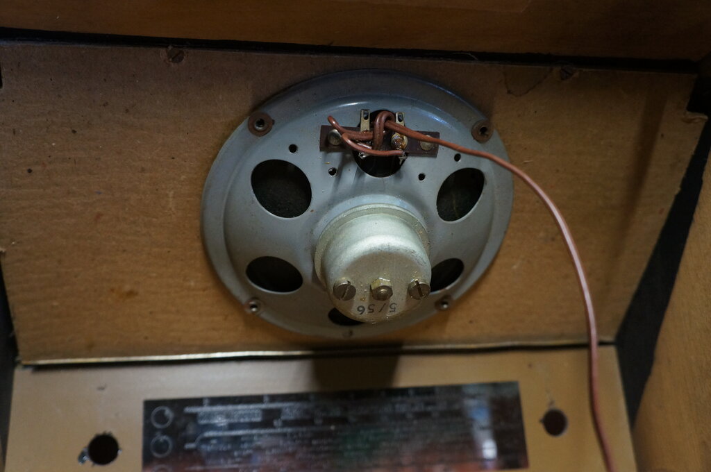
Speaker mounted on baffle behind the expanded aluminium grille.
Note 5/56 - either the 5th week or 5th month of 1956.
Chassis mounted in the cabinet.
6V6 Postscript.
As for the 6V6 which had been installed,
subsequent testing found it to be faulty. I put it into a set, upon which
it started arcing over inside.
I've heard of it being done, and seen
it - someone pulling a swifty, by putting any old valves (or other parts)
into a radio or TV just to get rid of it, when it's become too difficult.
As long as all sockets appear to be occupied, the buyer isn't immediately
alerted to the set having being 'got at'.
It's an attractive set, but has unfortunately been built to a cost - or lack of design knowledge.
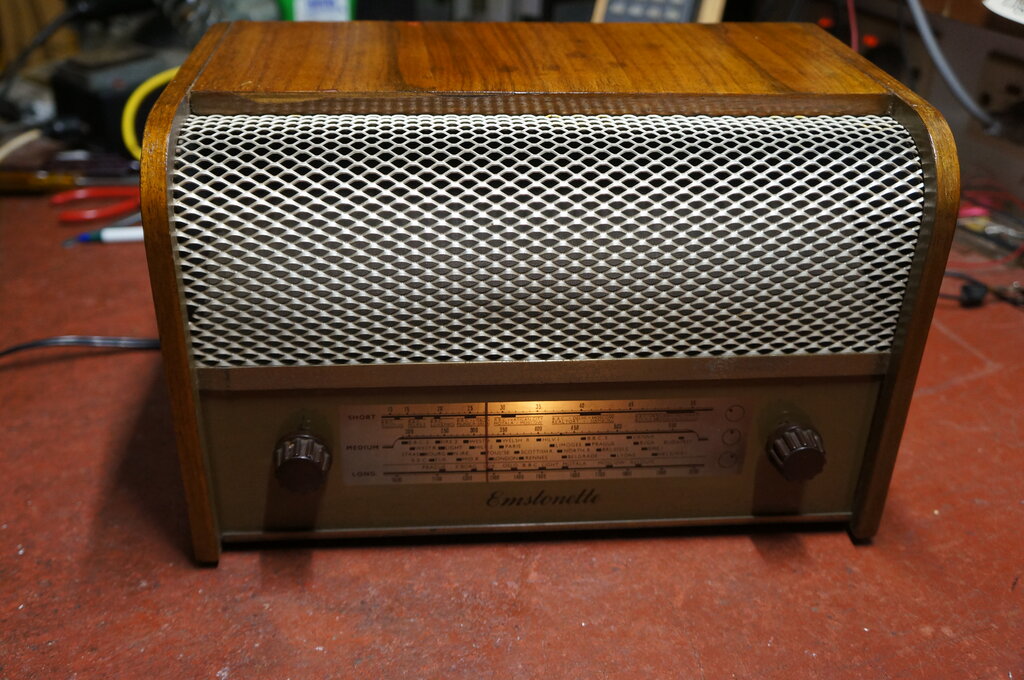
All complete.
That was something of a surprise to say
the least! I had completely overlooked the possibility of this valve because
it was introduced for military use in WW2, and was not normally used in
consumer equipment. In fact, it does not appear in most valve manuals.
Futhermore, the use of a 12.6V heater
output valve, in a series heater string operating off the mains, causes
more heat dissipation from the dropper resistor than a 35V or 50V heater
valve. In short, it's a very odd choice, when types 35L6 and 50L6 were
specifically designed for this use, and were readily available.
Nonetheless, lets have a look at the characteristics.
The most important thing is the heater current is 150mA, so it will certainly
be compatible with the heater circuit. The plate and screen voltage are
suitable, both being 250V.
And here we find an explanation for what
I thought was an unsuitable screen resistor. Remember that I replaced the
2.2k with a 4.7k because the screen voltage was too high for the 35L6.
Well, with a 12A6 in circuit, the original 2.2k would be satisfactory.
The other important characteristic is
the bias voltage. The original 330R cathode resistor should be suitable,
but only just. In the normal way, with 250V on plate and screen, and a
total cathode current of 33.5mA, the resistor should be 373R. However,
the screen and plate voltage is less than 250V in this set. Also, remember
the plate and screen voltages are measured with respect to cathode, so
are lower again.
And the biggie! The mysterious "why didn't
they get the heater dropper resistance right" is no longer a mystery! With
the 12A6 fitted, the total heater voltage is 12.6 + 12.6 +12.6 +12.6 +
35 = 85.4V. Add to that about 4V for the dial lamp, and the total is close
enough to 90V.
The voltage dropped across the 908R resistor
will be 136.2V. That means the mains should be 136.2 + 90 = 226.2V. Well,
fancy that! It all calculates properly now.
Why did they use a 12A6? This radio was
made to a cost, and by what seems like a backyard manufacturer. Also, remember
it was built when there were plenty of war disposals components available.
No doubt Emstonette got a bulk lot of 12A6's very cheap. And, lets not
forget that Heathkit did the same thing, using a 12A6 as a rectifier in
their FM-1 receiver.
Mike was also helpful in being able to measure the part of the dropper which is o/c in my own set for the 226-250V setting. It's 133R. So, the 100R fitted wasn't too far out. Also, he was able to tell me that the dial lamp is 6.3V, but 115mA. This is a very obscure current rating, but not atypical of what appears in some British and European sets. I could not find any reference to it in my Philips lighting catalogs. No doubt, the 115mA current rating means that it will get closer to 6.3V than the 150mA bulb I used. Alas, it will receive more voltage during the switch on surge. Not surprisingly, the bulb in his set was burned out.
So will I put a 12A6 in my Emstonette? Probably not; all the work fitting the 35L6 is already done, and works well.
July 2024: Dropper resistor failed. I used a 1k 25W adjustable resistor for replacement, set for 853R. Somewhat conveniently, when the resistor was set to this value, the unused end was 147R. Sound familiar? Yes, I could have used it for the dial lamp shunt. However, I decided against this, just in case some adjustment of the main heater dropper was required (it wasn't). Instead, the dial lamp shunt resistor was moved to the dial lamp socket itself, and is now 120R 5W, which further reduces the switch on surge across the bulb.