The screwdriver handle gave enough clearance to access the nuts.
For this article to make sense, it is necessary
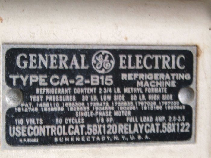
to learn about my CA-2-B15 here,
and also the CA-1-B15 here.
While the CA-2 evaporator blockage problem
had been completely solved, it became aparrent after running for many months
that there were problems with the float valve, either sticking shut, or
not seating properly. Given the success of the capillary tube conversion
performed on the CA-1, it was clearly obvious the same needed to be done
for the CA-2.
I also took the opportunity to do something
I'd been giving a lot of thought to; working on the cooling unit while
it was still fully charged.
Float valve problems.
Ever since I had restored the CA, there
were intermittent problems with the float valve. I had hoped that it was
the same substance that had caused the evaporator blockage causing the
problem, and that it would dissolve in the same way. The fault would make
itself evident in a number of ways. The most obvious was a sticking valve
where the frost line would suddenly start dropping, eventually causing
all the frost to melt. Without my compressor timer, the motor would then
run continuously. Another sign of a bad valve was an excess of refrigerant
flow. One could clearly hear the refrigerant rushing through the system,
even to the point of the float rattling. This meant the evaporator temperature
didn't get as low as it should. Usually, the float would stick around 5am,
when the room was at its coldest, and the pressure of the methyl formate
at its lowest. I'd arrive in the kitchen in the morning to find a defrosting
evaporator.
Persistent running did in fact seem to
clear out all the obstruction, and I had it running very well for a month.
Cycling times were excellent and it almost seemed ready to start using
to store food....but alas, one morning the valve stuck again. This went
on a few more times and it was becoming evident that the float could block
at any time, making the reliability unacceptable.
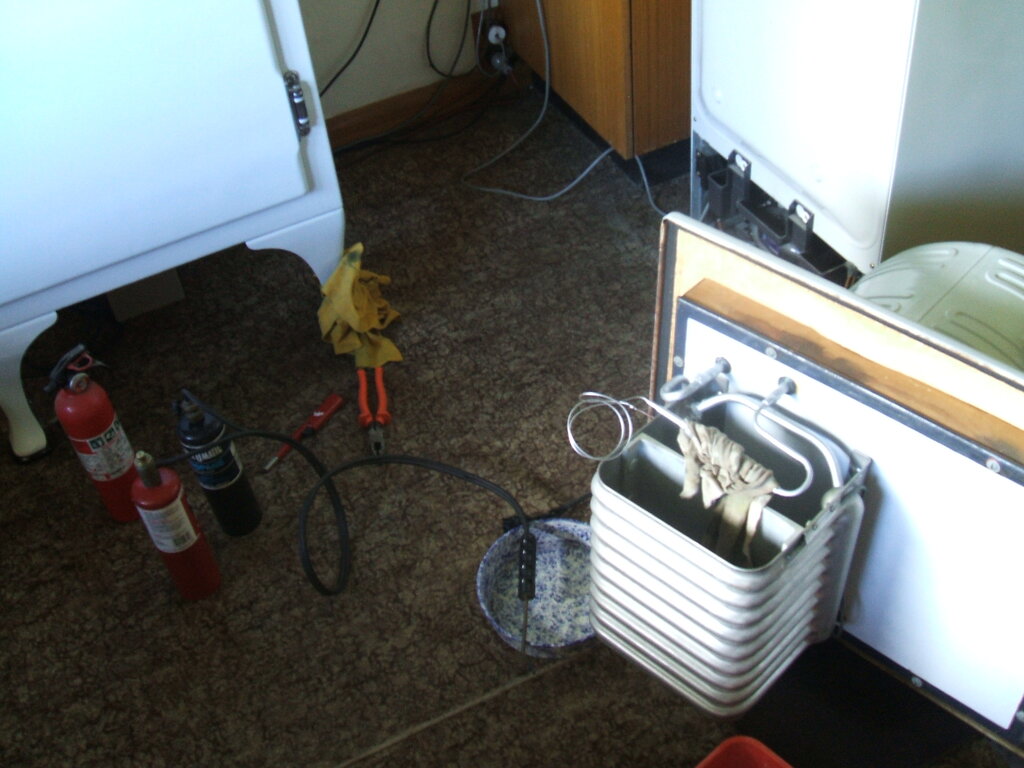
Replacing the evaporator bolts.
It had transpired that the nuts, bolts,
and washers I'd been sold for the evaporator were actually zinc plated,
and not stainless steel. After almost a year, signs of corrosion were evident.
With the cooling unit out of the cabinet ready for the capillary conversion,
the opportunity was taken to replace the hardware with stainless steel.
I was hoping to be able to do this without having to remove the evaporator
and top plate again. Indeed, not only was it possible, but was done in
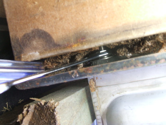
only a few hours. Carefully separating the top plate and getting an open
ended spanner into the gap allowed the nuts to be loosened. They, and the
washers were carefully hooked out. Installation of the new ones was just
a reverse of this procedure.
The screwdriver handle gave enough clearance to access the nuts.
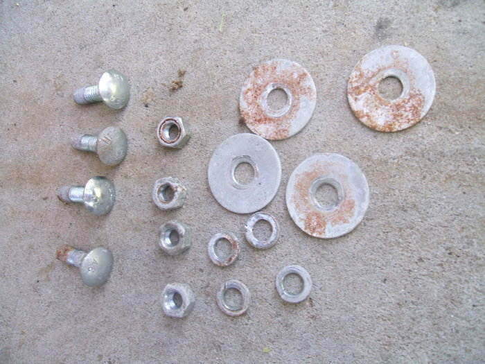
After a year, this was the condition of the zinc plated hardware.
Stainless steel eliminates this problem. The original screws were aluminium.
Making the capillary assembly.
Having already been through the procedure
with the CA-1 six months before, it was plain sailing this time round.
As before, the filter drier was prepared by drilling a hole and extracting
the pellets. It is not known what effect methyl formate might have, with
the possibility of them dissolving and blocking the capillary. Additionally,
methyl formate flowing past them could cause abrasion, breaking down into
smaller particles, again causing blockage. Incidentally, the latter can
be problematic with the modern refrigerants these filter driers are meant
to be used with.
Once the pellets were removed, a brass
screw was put into the hole and silver soldered over. Thus, we were left
with a simple filter having a coarse and fine strainer.
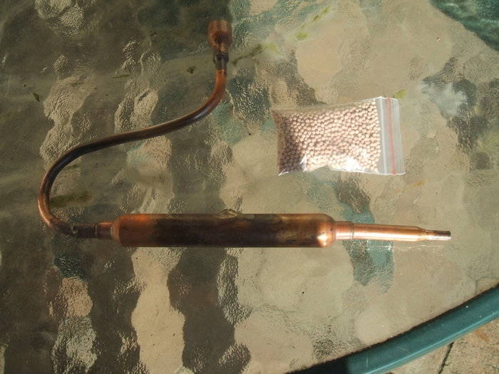
Filter drier with pellets removed, and 1/4" tube with 1/2" reducer
attached.
Because I had planned to do the installation
with the cooling unit charged, I thought it best to make the capillary
unit up as one piece first. Then only two connections need to be soldered
onto the cooling unit. As with the CA-1, I used 29" of .026" capillary
tubing. This is of course soldered into the end of the filter that has
the fine screen. To the other end was soldered a length of 1/4" tubing,
suitably bent, and terminated in a 1/2" to 1/4" reducer for connection
to the Everdur float seat tube.
Flow through the assembly was checked
with nitrogen, in case the capillary tube was blocked during soldering.
Preparations for the conversion and
working on the unit fully charged.
Methyl formate has a very convenient property
in that it's a liquid at atmospheric pressure, and it boils at 32 degrees
C. This means it should be possible to open up the cooling unit on a cool
day and not have to extract the methyl formate inside. I had given a lot
of thought about how to go about this over many months, so this was the
opportunity to try it out.
Everything went to plan...
Equalising the pressure.
First thing to do is get the cooling unit
up to atmospheric pressure so that no air flows in, and no methyl formate
flows out, when the unit is finally opened. As described elsewhere, the
CA unit is in a vacuum in its dormant state. Only the high side works in
a positive pressure, and that's only when the machine is working hard.
So, a connection to the nitrogen bottle
was made, and the unit filled slowly until the pressure was just above
0psig. At this point the nitrogen bottle was disconnected and the charge
valve slowly opened to equalise the pressure to the atmosphere. This needs
to be done slowly so as not to stir up the oil and methyl formate causing
any to be blown out.
Nitrogen is used rather than simply opening
the charge valve to the atmosphere. This is because we don't want moisture
entering the system, and also because nitrogen being inert will not support
combustion of the methyl formate - important given the proximity of the
blow torch during the work.
The cooling unit is brought up to atmospheric pressure with nitrogen.
This reduces the chances of the methyl formate igniting, and prevents moisture
entering.
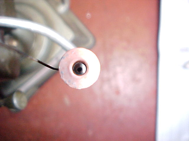
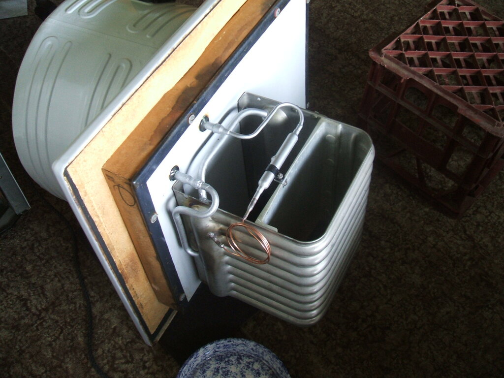
Cutting the float seat.
With the cooling unit on its side so any
liquid would remain away from the area to be worked on, the float seat
was cut off using a tube cutter and junior hacksaw.
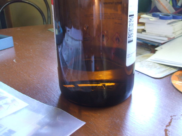
It was immediately obvious what the problem
had been all along. The seat assembly was coated in blue granules of what
looked like copper sulphate. Apart from that, the seat had a strange bleached
appearance.
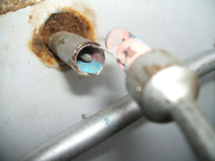
Soon as I saw this, it was the answer to the unreliable float valve.
The seat material looks somewhat bleached. My assumption is the
blue granules are copper sulphate.
Obviously some sort of reaction had been
going on. What, I'll never know as it would predate me owning this fridge.
Quite probably it was these blue granules that had blocked the evaporator.
As I'd hoped, I could not smell any methyl
formate vapour and the severed Everdur tube was dry.
Holding the flame from a stove lighter
near the opening didn't cause any effect, so it seemed I'd be able to solder
on the 1/2" reducer without any problems. And, so it turned out to be.
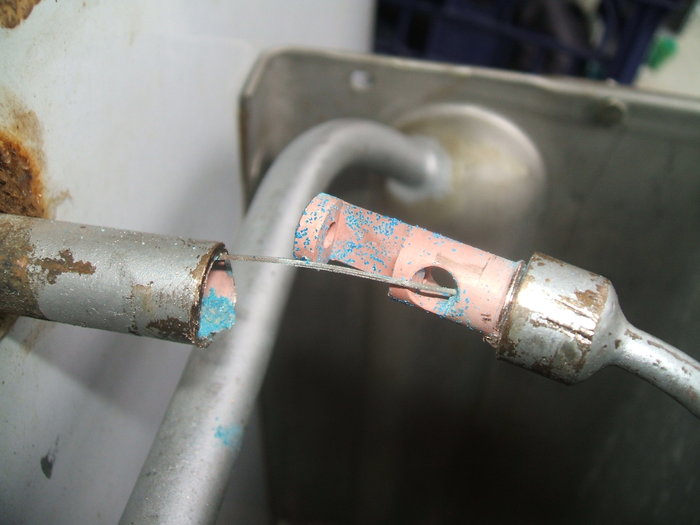
Evaporator connection.
Next was to desolder the 3/16" tube running
to the high side of the evaporator. Then, the capillary was inserted in
a few inches and soldered. The unit was now sealed again, and without losing
any methyl formate.
All connected and sealed. The unit is now ready for purging the
nitrogen.
Purging the cooling unit.
The astute reader may wonder now, if the
unit is at atmospheric pressure, how is the vacuum restored? Normally,
one simply connects a vacuum pump to do this, but as there's methyl formate
inside, which we want to keep, then we can't take that approach.
Simply, the unit is purged as if it has
NCG's.
To remove all the nitrogen took about
an hour and a half, following the GE purge instructions of one minute open,
and three minutes closed. It was clear as to the progress, for in the same
way as an NCG purge is done, the top of the condenser warmed first, then
the lower half, and then the float chamber.
By this time the evaporator was frosting,
and the whole exercise was a proven success.
Unlike with the presence of a needle and
seat, NCG's do not cause the rattling sound in the same way when the capillary
conversion is done. There is after all no valve for the NCG's to force
shut. What happens when NCG's build up in a capillary converted CA unit
is that the frost line drops first. The rattling begins after, when the
high side pressure has become higher than normal. This is one of the advantages
of the capillary tube conversion - the frequency of NCG purging is reduced.
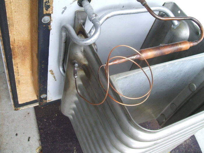
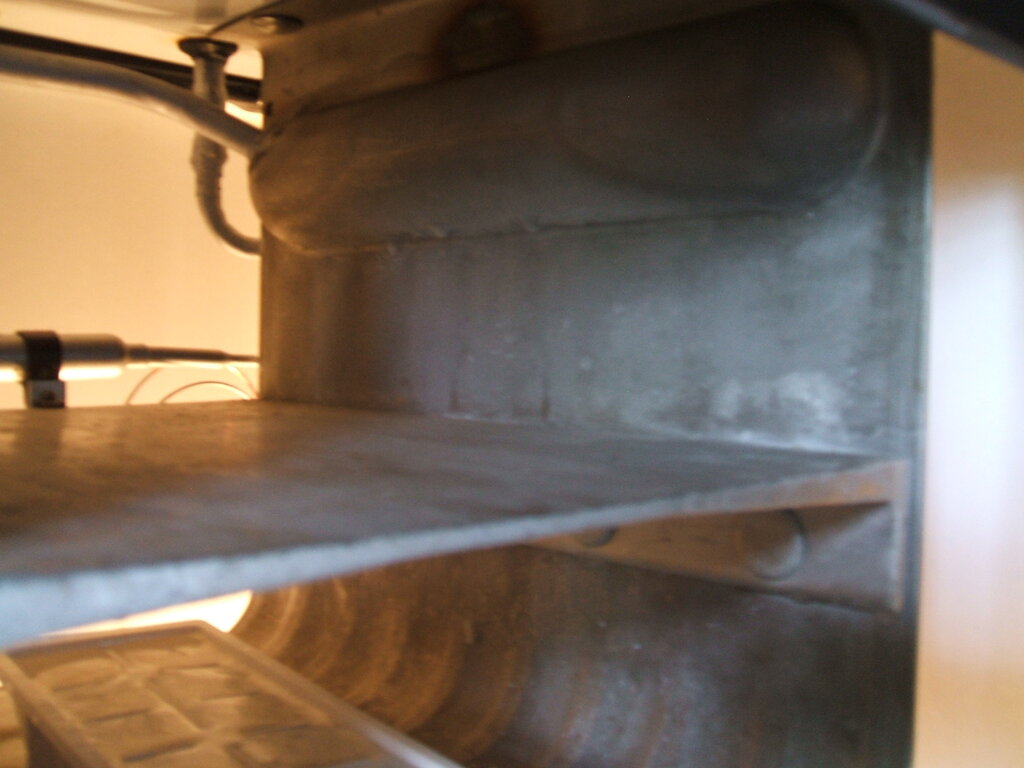
Tidying up.
As with the CA-1, I had to make a bracket
to secure the filter drier. It would be just too easy for something to
be pushed to the back of the evaporator bending the 1/4" tube.
I used a plastic cable clamp screwed to
the shelf. Silver paint was applied to all the new tubing, and a new 1/2"
grommet placed over the Everdur tube where it exits the cabinet top. This
was sealed with Silastic to prevent moisture entry. The cooling unit was
ready for installation, but I took the opportunity to do some cabinet work
first.
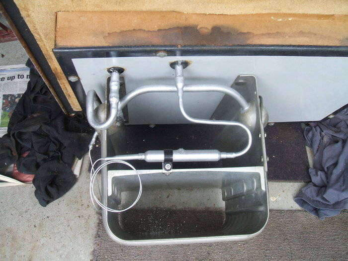
The filter drier is secured to the shelf and all bare copper painted.
A new grommet seals the float valve tube.
The cabinet.
With the cooling unit out, I decided to
do some touching up with the cabinet - things I had overlooked in my haste
to get everything together and working the first time round, a year ago.
The inside of the cabinet liner and the door needed a tiny bit of rust
clean up and touching up. It was also an oppurtunity to have a closer look
at the insulation, which was all dry and in good condition. One thing
I wasn't happy about was the No-ox-id cloth seal. While various holes and
tears can be patched, the problem is that it catches on the cooling unit
when lowered in. The slightly sticky surface doesn't help here. With the
success of the duct tape replacement I tried with the CA-1, it was obvious
the same would be appropriate for the CA-2. It make a big difference, forming
better to the inside of the cabinet, and staying in position. The top lowered
in very easily.
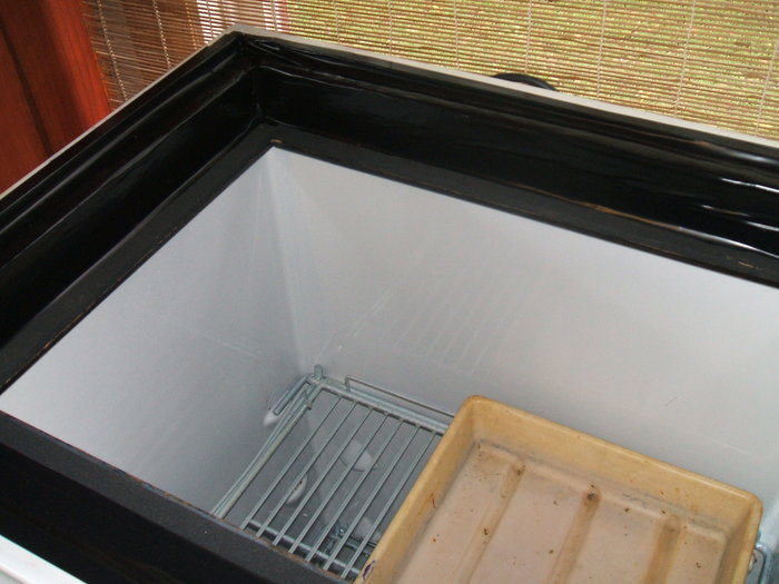
New duct tape top seal eliminates all the problems with the original
No-ox-id cloth.
The test!
As with the CA-1, I found it not necessary
to run the heater for very long to get a quiet start. It was just really
nice to see the cooling unit start cycling and not have to worry about
the float valve blocking. The cabinet cooled down without any problems
and it seemed all was well at last. The frost line was as it should be.
At this point I should say that the cooling unit was running with what
I presumed to be 3lbs of methyl formate. Apart from the initial 2.75lbs
put in when I first had the unit running, six months later I added another
4oz (.25 lb) in attempt to get the float to work more reliably. Not that
it did, it just worsened the cycling time instead.
Given that I'd found a charge of about
90% to be right for the CA-1, I'd wondered about the charge in the CA-2.
Again, it seemed that an overcharge is not evident with the frost line,
all it does is worsen the cycling times. And, these I was not happy about
- not as good as when the float valve did work.
The obvious thing to do would be to remove
some methyl formate, so about 75% remained, and then slowly add more to
get the optimum level.
Methyl Formate Extraction and optimising
the charge.
Not just for the purposes of optimising
refrigerant level, but also should one want to evacuate the system for
extensive work, I came up with a method of recovering the methyl formate.
The cost, at about $130 per litre, is
too high to allow the liquid to be wasted. A lot of the ideas used came
from jhigdon on the forum.
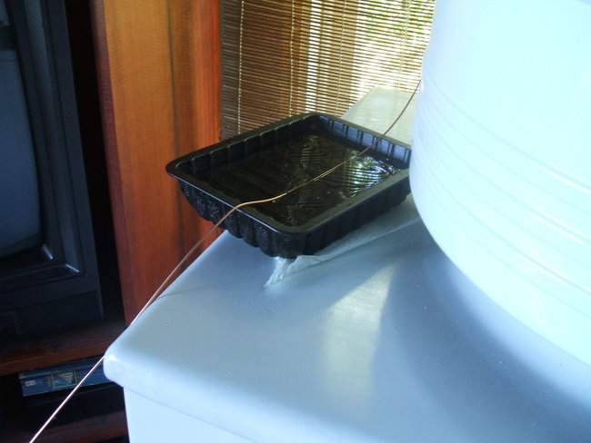
What I came up with was a connection that
could be screwed to the charge valve, and empty into a remote bottle.
Connection to the charge valve was by a flared piece of 1/4" tubing
to which was connected 8 feet of capillary tube. The charge valve adaptor
was used to connect the 1/4" tube to the charge valve.
As there would be vapour present, as well as the liquid, it was necessary to condense the vapour in order to recover everything. So, a long capillary tube, about 8 feet of it, was used to connect the bottle.
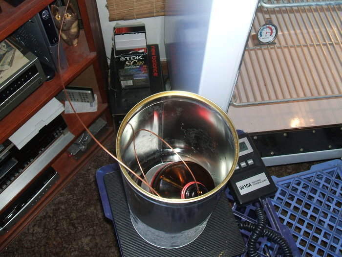
Capillary is inserted into empty methyl formate bottle for collection.
The bottle sits in an iced water bath to futher increase condensation.
The tin is actually that which the bottle came in.
By the time the vapour got to the end, some of it would have condensed. However, the most dramatic improvement was to run the capillary through an ice bath, and to also place the bottle in an ice bath.
Passing the capillary through an ice bath improved results considerably.
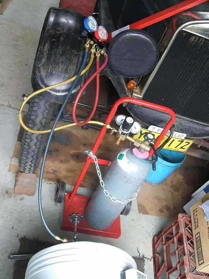
The liquid flow was continuous, and I could not smell any methyl formate. It is a slow process taking about three hours to get .63 lbs out. But, it does seem to be very efficient, and is easy to implement. Of course, the evaporator has to be warmed with a pan of hot water to get a positive pressure on the high side.
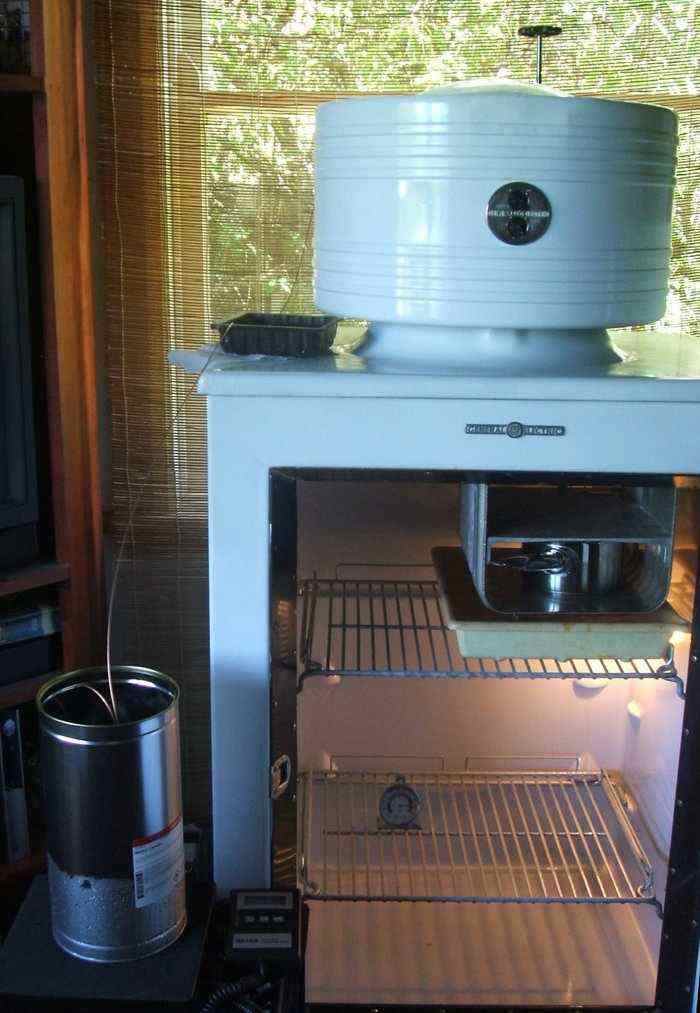
The complete extraction setup. Note the saucepan of hot water in
the evaporator to ensure positive high side pressure.
After three hours, .63 lbs had been collected.
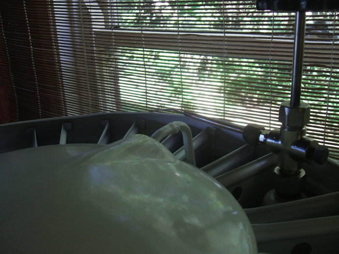
With .63 lbs out, and a charge of 86%, the frost line hadn't gone down, and the cycling was still poor, with short off times. So I removed more.

Right side header tank with 86% charge. Run times were still poor.
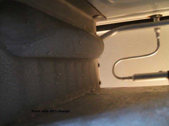
Left side header tank with 86% charge.
With 76% of the official charge, the frost
line had finally dropped, but was now too low. The right header tank had
no frost, and the frost above the shelf was not evenly spread across the
evaporator.
Now it was a matter of adding very small
quantities to bring it back, while keeping a close eye on the cycling,
optimising for long off times. The run times had stabilised around 2.5mins,
but the off times were still barely getting to 9 mins.
Putting in .04 lb quantities, and observing
the effect over a day got the off times to nearly 12 mins. That's what
I was looking for! Charge was now supposedly now 2.48 lbs, which is 90.2%
of the original charge.
It is very important that the cycling
times are observed when the room temperature is the same as the last reading
- the fridge is very much influenced by room temperature, and this can
mislead one into thinking the cycling time is worse, when all that has
happened is the room is much warmer. It is also necessary to wait a couple
of days to observe the effect, as the system takes a while to stabilise
after the change of operating conditions.
With such an improvement, I wondered if adding just a little more would get another minute for the off time. So, I added .03 lb. Alas, it had the reverse effect, with off times now around 9 mins for a 70F room temperature, approaching 11 mins for 60F. It does seem that the charge is actually critical within one percent. However, I was still not satisfied with the cycling time. It had been better with the float valve.
50 cycle operation.
A chance discussion on the forum made
me realise that my compressor is operating at about 1425 rpm, whereas in
the U.S, it's about 1750 rpm. While I'd always been aware of this, what
I hadn't thought about was reduced compressor capacity. It's reduced by
about 17%. Of course, the float valve accomodates this automatically, which
is why the monitor tops are sold for 50 or 60 cycle operation with the
same compressor. However, as I'd changed to a capillary tube, it suggested
that the not quite optimum cycling times were a result of the lower capacity.
A capillary tube only works properly with one set of conditions. And so
began a lot of intensive research into the subject.
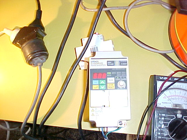
First thing was to observe what happened
when I ran the compressor on 60c/s. To do this, I used an Omron variable
speed drive.This is simply an inverter with variable frequency output.
There was a dramatic increase in the frost level when I tried it. This
confirmed that mains frequency really does make a difference. It also suggested
that the capillary tube was probably not optimum. I also found that the
start relay calibrated for 50c/s doesn't work properly on 60c/s. So, I
had to start it in 50c/s each time then wind up the frequency once started.
Capillary tube experiments begin.
Now I had to learn all about sizing of
capillary tubes. One would initially think that for less capacity that
the tube should be shortened to provide less restriction. And so I tried
using a 38" length of .0315" ID capillary. As before, I worked on the unit
fully charged and brought up to atmospheric pressure with nitrogen. There
were no problems doing this. I did however get to see what methyl formate
does in the presence of flame. It burns with a green/yellow flame. This
occured while removing the old tube from the filter drier. There was just
enough positive pressure inside, presumably from the room warming up, to
get the vapour out. There was no explosion or anything like that - it burned
just like a candle. I simply blew it out and kept soldering.
While there was no problem getting the
required temperature with the lesser restriction, the cycling times were
never better than about 9 minutes off time. Adjusting the charge level
didn't greatly improve things.
Longer tube.
There had been suggestions that the tube
should be longer for less capacity, and looking at compressor catalogs
seemed to verify this. It sounded illogical at first, until I started thinking
in terms of pressure rather than rate of flow. For the evaporator to cool,
there has to be a pressure difference between the high and low sides. The
greater the difference, the more it cools.
Imagine the compressor is reduced in capacity.
Now, for the same capillary tube, the pressure drop across it won't be
as much. So, the evaporator doesn't cool as much as it did before. Shortening
the tube is the worst thing to do, for now the pressure drop across it
will be even less, and the pressure drop between high and low sides of
the evaporator will be less.
In order to restore the correct pressure
difference between high and low sides, the capillary has to provide more
restriction to create a greater pressure drop.
As to how much longer it should be, that
would have to be found by experiment. While there are formulas available,
they are extremely complicated, and any of the internet based calculators
do not accomodate low pressure refrigerants. This is not surprising as
in the modern world, refrigerants like R11 and R123 are used with float
valves because of the size of the systems. However, I did get a starting
point by looking at recommended capillary tube sizes in various catalogs.
For a reduction in compressor capacity
of around 17%, the cap tube was about 1.4 - 1.5 times the length, depending
on refrigerant.
Time to try a longer tube, and this time,
I used 44" of .026" ID capillary. This gave the best results. I did find
the charge level had to be higher; about 2.7 lbs. The performance was now
as good as the float valve.
It is interesting to note that despite
the low pressure of methyl formate, the capillary tube sizing is not vastly
different to that used for R12 or SO2. Literature suggested that capillary
tube length is critical, but it's important to note that again this was
for high pressure refrigerants. My experiments revealed that with low pressure
refrigerants, it is not so critical.
All three of the tubes I tried did work,
and the difference between them was not huge. If one was to use .028" ID
tube as a reference, a change in 10" of length alters the off time by about
2 minutes.
Update: Improved Methyl Formate Recovery Unit.
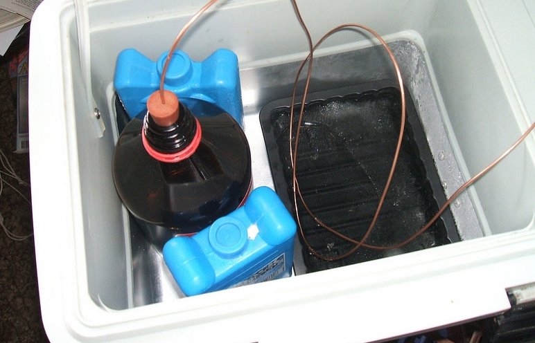
This is an improvement on the original method I used. Here, a car fridge keeps the bottle and ice bath cold throughout the extraction procedure. Two freezer blocks also help with condensation in the bottle. Importantly, a rubber stopper has been added to the bottle to prevent moisture absorption. Because it is now sealed, it is necessary from time to time to release the pressure build up. Extraction is more rapid with this new set up.
5th January 2014: For those who
haven't followed my CA-2 horror story from 18 months ago in the Flickr
forum, I'll briefly recap. The fridge as I got it had the usual damaged
tubing and thus the methyl formate had evaporated from it. During the restoration
I discovered the evaporator completely blocked. After trying to clear it
with such methods as applying 400psi of nitrogen, I eventually discovered
heating it in an oven cleared the flow, at least enough for the methyl
formate to flow and hopefully dissolve the rest of the solidified material.
And so I put it all back together and
sure enough the evaporator did work properly. Alas, it soon became clear
that the float valve was not happy, suffering from intermittent blockages,
or not restricting the flow enough. Sometimes it would actually run very
well. I'd hoped that running it over the last year would have improved
it (assuming more of the blockage in the float valve would dissolve).
With the success of the capillary conversion
I did on the CA-1, it was obvious the time had come for the CA-2 to undergo
the same operation.
So, far I've hoisted the cooling unit off the cabinet and it's in my garage ready for work (pointed so any jets of flame will go outdoors). Looking at my 18 month old work again, I have to say it doesn't look that good. But, it was all new to me at the time and this was the first time I'd worked on a monitor top, let alone any fridge at all. One of the other problems I need to address is that I was sold the wrong bolts for the evaporator - zinc plated instead of stainless steel, and one already has noticeable rust. And, as I'm trying to avoid removing the evaporator, replacing these will be a challenge. The no-ox-id cloth inside the cabinet top isn't brilliant, and given how effective the duct tape was on the CA-1, this might get the same treatment.
Anyway, on the the conversion. So far, the filter drier has had the pellets removed and a piece of 1/4" tubing soldered to it. This will connect to the cut off float seat via the 1/2 to 1/4" reducer. I was sure I got all the pellets out, but once I sealed the hole, there's one rattling around. I guess it must have been stuck and the heat dislodged it. drive.google.com/open?id=0B8_jm7K-ahMabVk4b1NhX3l0MWc
6th January 2014: Today's job was
to replace the evaporator nuts and bolts. This was successfully done in
only a couple of hours without removing the evaporator and top plate.
To do this requires unlimited patience,
and the dexterity of a brain surgeon. One must be careful not to drop anything
inside. Also, care must be taken not to stress the low side connection
when pulling the top plate away from the cardboard surround. I used an
open ended spanner to loosen the nut, then long nose pliers and a wire
hook to remove the spring washer, and then the flat washer and the neoprene
washer.
You can see the corrosion clearly in the
photo - and that's only one year!
Tomorrow is meant to be cooler weather
(below the boiling point of methyl formate), so hopefully I can do the
actual installation of the capillary tube.
drive.google.com/open?id=0B8_jm7K-ahMaRjRQaVN6Uk5MeVE
drive.google.com/open?id=0B8_jm7K-ahMaQXZ2MXhjUFBvQ0U
7th January 2014: The deed is done
and my CA-2 is now minus the dreaded valve seat. I was able to do the work
with the machine fully charged - and I'll talk about this in another 'sticky'
thread, as the info on how to do that is too important to get lost here.
What surprised me was when I cut the valve
seat off. I was expecting some sort of blockage, but not this:
drive.google.com/open?id=0B8_jm7K-ahMaeFNYVjFqVlIzY2s
It looks like granules of copper sulphate. The seat assembly looks a bit bleached; not the brass colour of the one in the CA-1. With that mess circulating around the seat, I'm not surprised the valve had difficulty working reliably. Here's another view:https://drive.google.com/open?id=0B8_jm7K-ahMackVNUTNMeHo4RWM
The filter drier and capillary tube assembly was now attached after cleaning out all the blue granules I could see. As always, it's wise to check nitrogen flow through the capillary tube before the final connection into the evaporator. As with the CA-1, I used 29" of .026" capillary tube. This is equivalent to jhigdon's recommendation of 40" of .028" tubing.https://drive.google.com/open?id=0B8_jm7K-ahMaMHB5UjBna2JkZEU
After a very long purge (reason for this
described in the previously mentioned thread), the cooling unit now exhibited
excellent frost lines:
drive.google.com/open?id=0B8_jm7K-ahMabTd6REZST08zelE
The refrigerant charge is as far as I'm
aware, much the same as the normal 2.75lbs. There was certainly no liquid
methyl formate lost during the procedure, and from what I could see, minimal
was lost in vapour form. At this stage it would seem safe to keep to the
"official" charge amount if one wants to, although as I've said elsewhere,
my CA-1 is running very happily with 90% charge.
The final job is to paint the new copper
bits, and make a bracket to support the filter drier.
8th January 2014: The valve seat
actually doesn't look too bad; as far as I can tell the seat is worn more
in the shape of a pentagon; not the 180 degree apart slots the CA-1 had.
I'll clean it up and try to take a close up photo. The needle looked a
little blunt, but that could have been the covering of copper sulphate.
I really don't know what caused the corrosion.
Moisture is possible as I believe it was run for some time open the the
atmosphere. But I wouldn't have expected what looks like an acidic reaction.
Today I finished it all off. I replaced
the no-ox-id cabinet seal with duct tape. That avoids the annoying problem
of the sticky corners getting caught on the cabinet top. It just fits in
better. I secured the filter drier with a plastic clamp attached to the
evaporator shelf.
It's been running in the cabinet for only
about an hour now, but it looks like I'll need to recalibrate the control
as it's switching off a lot sooner - no doubt due to the evaporator running
colder.
drive.google.com/open?id=0B8_jm7K-ahMaanVGb3oyaWw3U0E
drive.google.com/open?id=0B8_jm7K-ahMaR2h6bDczUy1hRVE
Once the temperature has stabilised I'll take the frost pics. Like the CA-1, the capillary converted CA-2 doesn't rattle much when started cold.
9th January 2014: Here's the CA-2 valve seat:
and a closer view:
.JPG)
11th January 2014: The CA-2 has
been running reliably since I did the capillary installation a few days
ago. I haven't even bothered to use my compressor timer with it. However,
my obsession with cycling times has not left me completely happy in that
regard. With a cabinet temperature of 40F, it's running about 3.5 mins
on, 10 mins off at its best. That's worse than than the CA-1. Running it
at 36F will give an on time of 4.5 mins.
I have noticed also that the evaporator
doesn't cool as fast as the CA-1, and doesn't feel quite as cold.
I know this fridge is capable of much
better performance; 30F cabinet temp with 3 min on and 15 min off when
the float valve was "just right". So, it's not just that the CA-1 has modern
insulation.
The only other thing that comes to mind is that the refrigerant charge is too much. Unlike the CA-1, I've started out with more refrigerant, rather than less. Given that jhigdon's recommendation is that a capillary conversion runs best with less charge, I think this could be it. Also, in the AK manual, it says that overcharge will increase run time and the evaporator will run warmer. I know it's SO2 but it's still a flooded evaporator/high side float system.
So, next experiment will be to extract some methyl formate and see what happens.
13th January 2014: That's
a valid point regarding how the fridge works under load, and at this point
the CA-1 is lightly loaded (my stash of chocolate), and the CA-2 has two
ice trays.
My theory was that the best case scenario
is with the fridge empty. In this case all it should need to be doing is
offsetting the heat that leaks through the cabinet insulation. So, run
time should be minimal. If it's running for long periods it seems there's
a lot of energy going in which is not efficiently removing the small amount
of incoming heat.
One observation is that when I added an
extra 4oz to the CA-2 about 7 months ago it immediately ruined the good
cycling times which never returned to what they were previously.
So now I've got the original 2.75lbs charge,
plus the extra 4oz, and the capillary conversion.
Having said that, the CA-2 has always
impressed me with its fast cabinet temperature pull down time.
This brings up another question...why
didn't the CA-1 have the larger evaporator? Surely its performance would
have been even better.
(Perhaps someone might like to try that
experiment).
To answer your question about ice making
speed, I've just placed two identical containers of water into both fridges.
So, we'll soon find out which freezes first.
I'm guessing it will be the CA-2.
13th January 2014: And the winner is...the CA-1. Frozen all the way through while the container in the CA-2 had just a frozen skin on the surface.
13th January 2014:
I must admit I was slightly surprised. I know the CA-2 has a greater cooling
capacity but thought even with it running less than optimum, that it would
still freeze faster than the CA-1.
I do remember though when I first switched
it on once I'd put it all back together in the kitchen, that the evaporator
didn't feel like the one for the CA-1 did. The way the CA-1 evaporator
cools when first turned on is almost supernatural compared to what the
CA-2 has ever done.
I've thought about an extraction unit
which I'll make up in the next day or so. I think we're in for a few heatwave
days though, so to keep as much as possible, and not lose too much in vapour,
I'll have to choose a cool time to do it. First thing will be to take out
that 4oz that never belonged in it anyway.
Good point re the pump. I think it's ok in view of what I have seen it do in the past - if I can get the same performance as it had with an optimum float valve, then I'm happy.
14th January 2014: I've
removed 10 oz. See the latest sticky thread regarding the process.
Assuming there was 3lbs to start with
(the original 2.75lbs charge + the 4 oz I later added), this should mean
there's about 86% charge now.
It's a warm day, and the machine needs
to recover from its trauma, so I'll see how the frost line is later this
evening. I don't expect the cycling times to settle until tomorrow morning.
15th January 2014: Not much improvement. The run time has decreased by half a minute, but the off time is pretty awful. With cabinet at 40F, Room 70F, on time is 3 mins, off time is 7 mins. There's been no change in frost line at all, and the equaliser tube is still frosted. That sort of suggests it was way overcharged to start with, and more needs to be removed.
15th January 2014: jhigdon said: Sounds like you're on the right track. I've found that when overcharged it will keep feeding liquid refrigerant to evap when in off cycle. Since a cap tube by design will pass more liquid than vapor, it will mimic an open float valve. On my CA units, the float chamber is pretty much empty when the temp has reached target.
17th January 2014: Thanks for your words of encouragement John,..I'm sure it's got to be the charge. I'm taking out another 10% (.3 lb)this morning, so we shall see. That will get it down to about 75% of the official charge - around where the CA-1 started working really well.
I think it's easier to start out with a small charge and add to it like I did with the CA-1, rather than start out with an overcharge and subtract from it, to get the optimum point.
17th January 2014: No A/C here. Until recent times few Australian houses had it...now it's standard on all new houses. But where I am, I can get away with just fans. The house is at least insulated in part.
I've finished the extraction for this morning. Now, I've got .920 lbs in the bottle. So, that means there should be 2.08 lbs in the fridge. That is just on 75% of the official charge. So, again I'll see how things are tomorrow.
The hot days at the moment really do affect
cycling times and cabinet temperature so I need to keep that in mind also.
But, I've got the CA-1 as a comparison.
When you see those ads with monitor tops
being tested in Death Valley, you have to wonder what the operating conditions
were.
19th January 2014: The
consumption is probably about the same as with the float valve; starts
off at 240W and gets down to around 200W (That includes 30W of the heater
& transformer).
As it turned out, I extracted too much
methyl formate. I was tricked by a frost line that didn't fall until I
switched it off and let it fully defrost, and then restarted. I guess the
evaporator didn't quite cool enough to lose the frost it already had, while
still running.
It's much more obvious when you add refrigerant
to get the frost line.
Anyway, I'm carefully adding small quantities
back into the system, just until the right tank gets an even frost just
above the bottom. It seems the quantity might be more critical than I thought.
I'm adding it in only .12 lb quantities this time round.
No more for today, it's already a bit
too warm to add any extra - I'll see how this lot goes.
19th January 2014: Just some interim
horrible thoughts: 1)there's something wrong with the capillary length,
2)the check valve in the compressor is not working properly.
One does hear the rushing of refrigerant
for about 20 mins after shut off, but I realise there's no float valve
now to prevent that. So, what the manual says on the subject doesn't really
apply now - not sure how one would identify a leaky check valve once the
capillary is installed.
One other thing which may be a good sign actually, is that while all of this has been going on with its short off times, the condenser, cabinet top, and float chamber are warm. That suggests that actually the heat pump is doing its job extracting heat from the cabinet. So, maybe the insulation just isn't up to 100F room temp? Or the door seal leakage is too much. It was after all the start of winter when the performance was at its best. There's a cool change over the next few days so this could tell me if it's heat entry being the problem.
20th January 2014: 20 Jan 2014 at
02:42 ChrisJ said:
John,
I'm curious, with a 100F ambient what
happens if you turn the t-stat up to #9? How low can it pull the cabinet
temp down?
It was getting down to at least 8F but
I didn't wait for a long time. The room temp is now 74F and likely to stay
that way or a bit cooler for the next week. The compressor is running noticeably
cooler. Frost is ok on the LHS, but just needs to fill the upper RHS now,
so I'm adding smaller quantities now.
I've found out what happens when you try to add methyl formate when the high side is still warm - quite an interesting boiling reaction. You have to wait about 10 mins before it will suck it in.
20th January 2014: 20 Jan 2014 at
11:42 ChrisJ said:
The cabinet temp got down to 8f!?!?
Bad mistake :( That was the evaporator
temp. Cabinet temp was about 47-48F
With the room now at 82F, the cabinet is 42F with the same control setting. Frost line with the latest addition of methyl formate is just above the bottom of the header tank. The frost line is not even, so I might add a little more tomorrow, but I think it's pretty much right for the charge now.
21st January 2014: Things are looking a lot better this morning. Room temp is 68F and cabinet temp is 40F (same control setting). On time is 2.5 mins and off time is just on 9 mins.
That is no worse than a DR-2 with stainless steel evaporator quoted as running for 4 mins and off for 10 mins.
I'm going to leave the charge as is (approx
86%) for a while and continue to observe it.
I do know there is a slight gap in part
of the door seal which could account for part of the reason for this fridge
being so influenced by room temperature, so I'll attend to that next.
Testing on 60 Cycles.
13th February 2014: After watching
Allan's video of the CA compressor running open, something immediately
dawned on me...all of you in the U.S have your compressors running faster
than mine.
A two pole induction motor on 60 cycles
runs at about 1750rpm...but on 50 cycles it's about 1425rpm.
According to the manuals for each of the
three series of monitor top, the compressors are suitable for 50 or 60
cycle use, so the only changes were the start relay and controls.
Now that I look at the tags for both frequency
models, I see that the current consumption is higher for 50 cycles, which
is what I expect when a 60 cycle motor is operated at the lower frequency.
Talk about being blind to something staring
me in the face! It's no wonder my wattage readings are a little higher
than everyone else's.
I suspect that therefore the 50 cycle
start relay doesn't just have beefier contacts, but the current calibration
would be slightly different also.
Some other curious points; lower rpm in
theory would mean a longer compressor life - not that this is an issue
with CA or later models.
But, I'm wondering how this affects refrigeration
performance....lower rpm taking longer to build up pressure thus lengthening
run times? Or does pressure never build up as much? All the specs in the
manuals are for 60 cycle only.
Anyway, it's just a bit of trivia I thought
I'd share.
13th February 2014: 13 Feb 2014
at 16:48 jhigdon2 said:
I completely forgot about that too, that
it 1425 where you live. Hmm I wonder if a cap tube adjustment is needed.
Especially on the CA2. It has a larger Evap and may require shortened cap
tube to correct maybe.
Maybe not so trivial now :(
Regarding the CA-1, I remember back in
the Flickr days you mentioned using 50" of cap tube for your CA-1, before
you decided 40" was better. Could it be that me using 40" would explain
why it's working well, because on 50 cycles it's equivalent to 50" on 60
cycles?
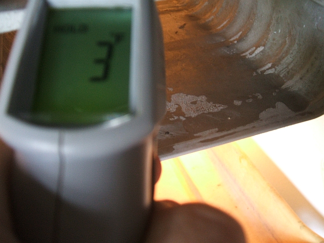
It could explain my present CA-2 performance and why it isn't quite as good as when the float was working correctly. The evap temp doesn't seem quite as low (I got 3F with the float at one time) and the off times aren't as good. I presume the float valve would self regulate with lower compressor speed.
Until now, I've assumed it was refrigerant
charge - perhaps my experiments there have all been in vain.
Maybe a proportional reduction in length
is in order.
14th February 2014: coldspaces said: Less pumping capacity of the 50 hz model with the same amount of cap tube as a 60 hz model could mean slightly higher suction pressure and temp. Same amount of refrigerant can flow through the cap tube with less pumping capacity to remove it from the evap. If shorting the cap tube doesn't help you may have to try a little longer cap tube. More restriction too keep the suction pressure and temperature lower. Of coarse the flow must be enough to get good frost line height and proper oil return with out causing excessive hi side pressure.
Would be interesting to know if modern systems made for 50 hz use a different cap tube then the same unit made for 60hz.
Don't really know how the float would have reacted to the slowing running compressor, might be less sensitive that the cap tube is.
Coldspaces
14th February 2014: 14 Feb 2014
at 10:08 jhigdon2 said:
If you have what seems like the correct
amount Of refrigerant and you still have difficulty getting a flooded evap.
By that do you mean low frost line with
optimum charge (like I'm getting now)?
One interesting thing I hadn't noticed until now, is that capillary tubes are normally used with much longer lengths. I'm wondering how the regulation is affected with short lengths as used with the CA. Maybe this is why I can't find any cap tube calculators for similar p/t refrigerants like R11 and R123.
jhigdon said: Yes short lengths of cap tube for the CA because it's flooded evap and such low pressures. With the lower rpm it may be having g difficult time flowing enough to keep evap flooded. If my understanding is correct, you have plenty if not to much refrigerant in systom but performance hasn't been optimal. I am known to be a little heavy handed but I would chop off about 18" of cap tube.
14th February 2014: For .026" tube
as I'm using, that would equate to a 16" length left, rather than 29" as
at present. Quite a drastic reduction.
Would it be better to use a larger diameter
tube, so as to get more length and better regulation, or does it not work
that way?
One thing I will try shortly is a variable speed motor drive that can run up to 400Hz. I'm testing one now and learning how to program it. If it can handle the start up current of the compressor, I will be able to see just what happens with the present setup on 60Hz.
14th February 2014: 14 Feb 2014
at 12:39 ChrisJ said:
If your machine can run at 60Hz, why does
it have a different tag?
Wouldn't the different tag suggest the
motor is wound differently?
According to the manuals the motor is
the same for 50 and 60Hz, and this would be the reason why the different
tags show different power consumption - higher at the lower frequency.
If the motor was actually designed for 50Hz, it would have more wire in
the windings to give more inductance, and power consumption wouldn't be
higher. Note that in the DR manual they advise the upper voltage limit
is lower on 50 cycles. There's a rule of thumb that when a 60Hz induction
motor or transformer is run on 50Hz the voltage should be lowered slightly
to prevent overheating.
It's an interesting question regarding
the controls - why didn't they make them all with more rugged contacts
so they'd work on both frequencies? They knew about that since the DR.
Would the saving in contact material costs be that significant?
The start relay calibration will probably
be a bit out; might take a little longer to drop out at start up because
of less current draw.
Maybe the type R relay had that sorted
out - the CK tags do say 50 or 60Hz, and would lead me to think they had
also upgraded the control contacts by then.
15th February 2014: I'll try using .0315 tube so as to get a decent amount of length. 35" of that is equivalent to 22" of .028. One article says that a capillary tube should really be between 5 and 16 feet - but that's for typical high pressure refrigerants, of course. Seems no one uses them for low pressure.
What I'm having a hard time understanding is the run times are very good. Typically 2 mins 30 sec for 40F cabinet. It's the off times I'm not happy about; typically 9 mins in a 68F room. It seems to me that the problem is the evaporator warms up faster than it should when the compressor switches off. Is this because there's not enough refrigerant in the header tank to maintain the cold between run cycles?
I'm still testing for charge valve leaks, so might be a little while before I get stuck into this project, but for now I'll see what happens when I run it on 60 cycles.
15th February 2014: Well this just
had to open the can of worms didn't it?
The sound of the motor at 60Hz is noticeably
different compared to the usual 50Hz. Same but just speeded up a bit. Here's
how I got the 60Hz. The Omron variable speed drive converts 240V AC 50Hz
to 0-400Hz. It's just effectively a switchmode power supply type of inverter.
The 60Hz output then feeds the 240V-120V transformer and fridge as before.
The 50Hz E3 relay doesn't like 60Hz. The motor sits there buzzing unable to start, so had to turn down the frequency to 50Hz and then back up once started.
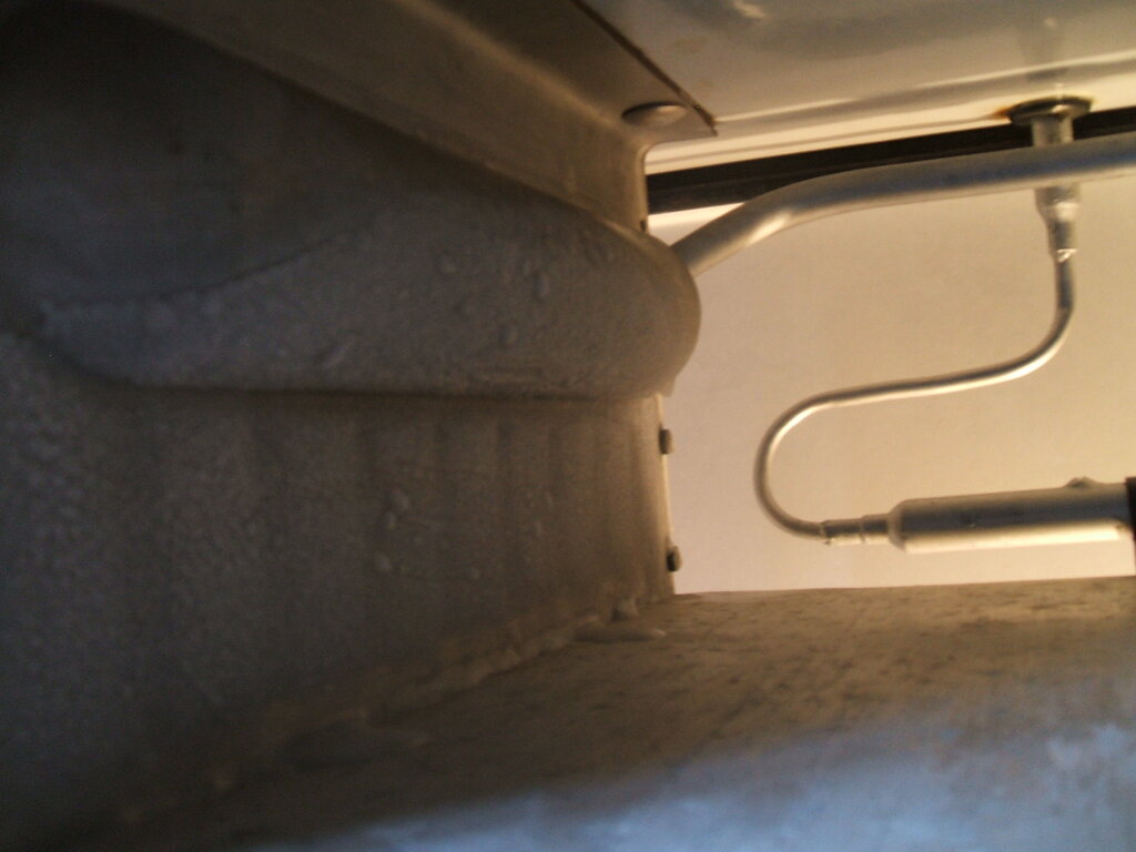
Frost line changed dramatically over a couple of hours:
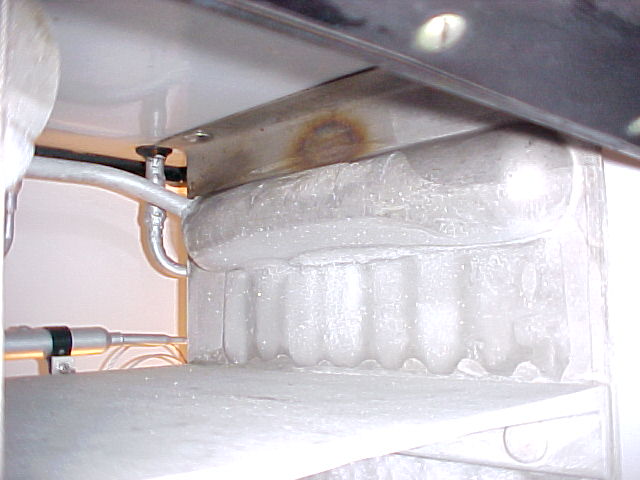
See the lumpy bit along the bottom of the
header tank around the middle. That's where it is on 50Hz. You can see
how much it has risen on 60c/s - to the top of the tank!
And for the left tank, you can also see
the new frost line rising above the old:
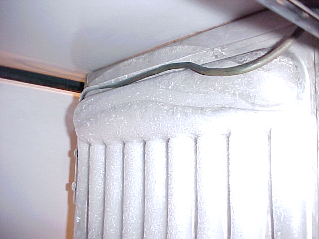
Right to the top of the evaporator on 60Hz.
So....it puts everything in a different
perspective doesn't it? 60Hz users can forget everything I said about 90%
charge, and 50Hz users can forget everything I said about cap tube length.
15th February 2014: 15 Feb 2014
at 14:29 jhigdon2 said:
Well isn't that a hoot. Looks like you've
proved this theory quite nicely.
Seems like I'll be following in your pioneering
footsteps now for the 50Hz CA's.
I'll get some .0315 next week and
think about what next to do. I'll probably just do the operation on the
kitchen floor - really just a matter of bringing it up to 0psig again,
swapping over tubes, and purging it.
I'm not going to touch the CA-1 at this
stage - that's my star performer and don't want to risk ruining it - lucky
I used a shorter length on it, although I'm sure further improvement is
possible.
15th February 2014: I have 90% charge in now, and as you can see it went up to the top of the tanks on 60Hz, so it's too much. Maybe 80% or a bit less would be appropriate. In view of what I've seen, my recommendation would be to start at 60% and gradually add very small quantities until it reaches about 1/2 way up the right tank and see how the cycling times are then, tweaking if necessary. With my present set up, I was finding as little as 1% change in refrigerant level could change off times by about 2 mins.
I can't see the video until I'm back at
work, but if it's the one I think it is, then it sounds the same. I always
knew the machines ran at different rpm. It's more noticeable when you actually
change from 50 to 60Hz while running, but if I hadn't heard it for a few
hours it's not so obvious. I'd had the AK manual long before I actually
had any monitor tops, so was aware of the different rpm, but the effect
of that just didn't dawn on me until two days ago.
We'll get to see the charge valve screw
sooner than I thought.
15th February 2014: jhigdon said: This is getting intensely interesting now. I knew something had to be amiss, but was stymied. The 60hz makes all the difference! Well now it looks like a cap tube adjustment is in order. I am optimistic that you will get it right. Once you have the cap tube problem sorted out you will see much improved performance. It should easily flood the evap and require less refrigerant to do it. You won't miss the float valve.
Adjusting the Capillary Tube for 50 Cycles.
22nd February 2014: Following on
from here monitortop.freeforums.net/thread/221/mains-frequency-monitor-top,
I've started experiments.
In view of longer capillary tubes being
superior to short ones, I decided to go up a size. Previously, I had used
.026" ID tubing. As it was only 29", to shorten it much more would have
to reduce any kind of regulating properties. So, I went up to .0315" ID.
John's recommendation for a starting point was 22" of .028". That's equivalent
to 38" of .0315". In theory same flow rate but longer tube. Literature
I've seen suggests a cap tube is best between 5 and 16 feet. However, that
is for positive pressure refrigerants, and may or may not be applicable
to negative pressure types.
There are calculators for sizing a cap
tube, but again only for positive pressure refrigerants. The modern equivalents
to methyl formate; i.e. R11, R123, etc, are evidently not used with capillary
tubes, but that's not surprising because they're not domestic refrigerants.
So, no calculating tables there. Thus, experimentation is the only way.
As before, I worked on the CA fully charged. By bringing it up to atmospheric pressure with nitrogen, the methyl formate reverts back to liquid - assuming this is being done on a cool day, which it was. I worked on the kitchen floor this time.
It was straightforward replacing the tube,
but as there was some methyl formate vapour in the filter drier there was
some flame when I withdrew the old tube.
It burns with a green/yellow flame with
the same intensity as a candle. No explosions, just a gentle flame.
New tube was installed and purging done until the float valve was warm. I haven't bothered painting the new tube because somehow I suspect I'm going to be changing it again.
At this point I've only just put the cooling unit back in the cabinet, but so far, and during the purging procedure, I'm getting the impression that things aren't as good as they were. I'm suspecting the tube needs to be longer, maybe about halfway between what it was and what it is now.
22nd February 2014: I noticed that the performance got worse the more I purged it. Surprisingly, the evaporator did actually start to get cold even at atmospheric pressure. That makes me think it prefers a lower refrigerant flow. I'm tempted to partially crimp the capillary before I pull it out. Anyway, I'll run it for the rest of the day to see what it does, and record performance. The swap over job only takes about 3hrs including purging and it's really quite straightforward.
22nd February 2014: True, the CA-1 usually runs with a cool float chamber. I haven't totally given up on the 38" just yet, but it didn't startle me with its performance like the CA-1 did. To be objective and scientific, I have to wait until the cabinet temperature and cycling stabilises, which will happen by tomorrow morning. Then I can take note of frost line and cycling times to make further decisions.
23rd February 2014: I may have been
a bit premature with my pessimism. After waiting until next morning to
for everything to stabilise, things are quite different - maybe even better
than the old cap tube.
Room temp was 64F, cabinet temp 34F, run
time 3 mins, off times 8 mins. That's still with the previous charge (90%).
Now, that's a lot better than the old cap tube when I first installed it
and hadn't optimised the charge; it was 40F cabinet temp, 3.5 mins run
7 mins off.
What caught me out was that with the CA-1,
I started with it in a vacuum and added refrigerant - the evaporator coldness
was far more obvious this way. With the CA-2, both times I've started with
an overcharge of refrigerant already in it and then restored the vacuum;
i.e. the other way round. Anyway, the end result is the same, provided
you give it time to stabilise.
At the moment, I'm tabulating the performance under different conditions. Control is at #9 today and I'll record the cycling times for that, once stabilised by tomorrow morning. First some good news. I haven't seen this since the float valve was working:
It switches off at this point.
It seems the evaporator is capable of
getting down to a reasonable temperature, so perhaps refrigerant charge
is all I need to adjust for optimum cycling.
Next is to tabulate cycling times for 40F
cabinet temp, as this is what I was running at before, and will give me
a real comparison.
After that is time to experiment with
the charge.
24th February 2014: 28F in the cabinet
this morning!
And I forgot to mention the power consumption
is 20-30W less with the new cap tube. The condenser runs much cooler too.
A sign of good times ahead maybe? :)
Frost height is similar to yours John,
though lower at the ends on the right tank.
9th March 2014: After much data
collection, discussion with John, and having to actually learn about capillary
tubes, it was becoming clear that my second attempt at using a shorter
tube was not working properly. The best I could get out of it was 8 min
off times.
Looking in compressor catalogs, it was
clear that for a lesser capacity compressor, the cap tube should be longer.
That doesn't sound logical at first, until one thinks about pressure difference
rather than rate of flow. So, the question is how much longer?
There are a couple of well known cap tube
calculators around; one being from Danfoss and the other Tecumseh. General
comments in other forums suggested the Tecumseh one was the more accurate
of the two.
The catch of course is that data to do
with cap tubes only includes modern positive pressure refrigerants. But
that aside, it should be possible to find out what the relationship is
between compressor capacity and cap tube length. I found that for a 19%
loss in btu that the cap tube was about 1.4 to 1.5 times longer. The lower
the refrigerant pressure, the longer the tube.
So, with that in mind, the next starting
point should be 1.5x 40" of .028; i.e. 60".
The next bit of information that kept
coming up was the tube should be as short as possible. In other words,
the smallest bore that still allows flow. In view of that, I decided to
go back to .026" tubing. That then gives a length of about 44".
This morning, the third tube went in. As
before, it all was done in a few hours without any problem. The usual green
flame greeted me when soldering around the filter and evaporator connections,
but nothing to worry about. With the unit purged, it's sitting back on
the cabinet gradually coming down to temperature.
We'll see if this one is any better.
14th March 2014: Latest update is
the third attempt has also failed. In fact a pattern has emerged here.
You could, in fact, get a monkey to pull a number out of a hat to determine
cap tube length, because whatever is chosen gives similar results; 2-3
mins on and 7-9 mins off. This is despite the huge variation in lengths
tried.
Interestingly, there is still a critical
refrigerant charge with whatever length is used, whether it's the right
one or not.
It does actually appear that I've stumbled
onto the well known limitation of the cap tube. It just cannot regulate
as well as a float valve.
What appears to be happening is that attempts
to use a short cap tube, to increase refrigerant flow, doesn't give the
required pressure differential, and conversely, a longer cap tube, to give
the required pressure differential, is preventing the evaporator flooding
completely.
In fact, the book that Coldspaces has
provided a link to discusses the limitations of cap tube converting float
valve systems; babel.hathitrust.org/cgi/pt?id=mdp.39015002946328;view=2up;seq=718
In summary, cap tubes cannot provide the
required change in refrigerant flow for large flooded evaporators. The
book does suggest evaporators requiring more than a pound of charge are
problematic. This is why we will never see cap tube data for R11 &
R123.
Evidently, a 16-19% loss of compressor capacity is too much for the CA-2 to work with a cap tube, although the smaller CA-1 gets away with it...just.
14th March 2014: 14 Mar 2014 at
10:54 allan said:
"Also been noticing that most charts start
with a .031 or .036 I'd cap tube for the 1/5 to 1/8 hp range. Has anyone
tried the larger bore cap tubes?"
I've been down that path too, thinking
that the lower pressure would suit a wider bore. I used .0315" ID for the
second tube experiment.
It's not a question of the fridge working
or not working, when you can't make the system balance.
In fact, with all three cap tubes I've
used, I could put the CA-2 on ebay as a working fridge. No one would be
the wiser. It cools more than adequately (28F cabinet temp @ #9), and it
cycles infrequently enough not to cause suspicion.
The problem is I'm being a perfectionist
who wants the long off times the float valve used to provide. Short run
times are easy - I can pluck a figure out of the air that will do that...but
it's the off times that really show up how efficiently the system is running.
And at 25 cents/kwh that's important.
I'm sure the CA-1 isn't really balanced
but it's so close that it isn't a problem.
Still, I'm going to give the cap tube one last chance and try an in between length this weekend. If that's still no improvement, then back to the original, which did seem to be the most promising out of the three - almost 12 mins off times. Tolerable until something else comes up.
Meanwhile, I should start investigating other kinds of metering devices; ones that can't leak, and ones that can tolerate years of methyl formate flowing through them.
14th March 2014:14 Mar 2014
at 12:10 ChrisJ said:
"John,
You forgot something else.
Besides the cost of electric and the fact
you're a perfectionist there is also the fact you have guys like us that
are all competing for the best run times. Once you get yours down to something
you like someone is going to try and beat it and then you're going to be
back at it. :)
Well Chris, after my journey into the
world of capillary tubes and bringing the engine hoist into the kitchen
every weekend, I don't know about that :)
If I can get 15 mins off time I'll leave
it at that.
What I need is a way of calling GE spare
parts dept in 1942 to buy a new float valve with the improved seat :)"
Yes, just a crimped tube has been on my mind and I haven't eliminated it from possibilities yet. Although, learning what I have so far, I suspect it will behave the same as a cap tube in an unbalanced system. It's nevertheless on the agenda of possibilities, along with solenoid and TXV's if I can find ones suitable for the methyl formate system.
14th March 2104: 14 Mar 2014 at
12:04 cablehack said:
It cools more than adequately (28F cabinet
temp @ #9), and it cycles infrequently enough not to cause suspicion.
The problem is I'm being a perfectionist
who wants the long off times the float valve used to provide.
14 Mar 2014 at 13:29 birkie said: Interesting
- so the criteria for failure is short off cycle times? I don't think I
got that, but then again I don't know what CA cycle times should be.
If the on/off controls on these machines
are based on evaporator temps, what physical phenomenon is responsible
for determining long run times? Continued boiling in the evaporator during
the off cycle? Heat capacity of the evaporator and liquid refrigerant coupled
with minimum temperature the evap reaches? Both?
That is pretty much my understanding of
it. With insufficient liquid in the evaporator (long tube) it takes a shorter
time for all of it to boil off, even though what's in there is cooled enough
- just less of it, so the compressor has to run more frequently.
With the tube shorter so the evaporator is easily filled, the difference
in pressure between high and low side doesn't cool the liquid down to such
a low temp. So, again the compressor runs more to compensate.
What seems to be the goal is to get the
evaporator full, and at the same time with a large pressure difference
to get it as cold as possible.
The CA cycling times are meant to be roughly similar to those quoted in the DR and CK manuals; better than a DR, but not quite a good as a CK. At the very best, I did get 17 minutes off time once with the CA-2 using the float valve.
18th March 2014: At last I'm getting
an improvement with off times.
New information has come to hand from
the Nickerson & Collins book. This is the best cap tube description
I've seen yet. members.iinet.net.au/~cool386/ge_service/N&C%20Introduction.zip
Important points are made:
A receiver (i.e. the
disused float chamber) is quite acceptable for cap conversions,
A cap conversion works
the same way as a float valve - this is pointed out several times.
Evaporators can be
flooded; in fact this is quite normal, and no limitation on size is mentioned.
It gives a much more positive outlook on the subject compared to the Althouse & Turnquist book.
I had also forgotten about GE's own high side restrictor, evidently tested in a S02 monitor top. It looks like it could be substituted with a length of 160" cap tube, going on the dimensions given in the patent. It also includes a receiver. www.google.com/patents/US2069630
So, with all that encouraging information,
I decided not to make any rash decisions and alter the cap tube just yet.
All the calculations keep pointing to 1.5x length for the drop in compressor
capacity I have, so decided to persevere with it for a while.
At this point it seems the system is just
undercharged. I thought with nothing to lose now before I change the tube,
I'll just add MF anyway to increase the frost line - just to see what it
would do. The N&C description implies it could do with a good deal
more charging than I've been giving it.
After adding .065 lbs last week, I noticed
a day later that off times had improved consistently by around a minute
or two. I added another .035 lbs two days ago, and now over 11 mins off
time depending on room temp. What is pleasing is that the run time has
not increased; still around 2 mins 40 sec.
So, my agenda now is to add extremely small amounts several days apart and see how far I can push my luck. And this brings up another thing that N&C makes a point of; cap tube systems respond much more slowly when refrigerant is added, than does a float valve. The reason should be obvious, but it's important to keep in mind for those doing the conversion.
11th April 2014: The experiments
are now complete, after tabulating six pages of data, and trying three
tubes with different levels of charge, along with different thermostat
settings for each, and of course, many pm's with John. Although it has
been frustrating at times, it has been extremely educational, familiarising
me with cap tubes. This would not have happened had everything worked straight
off.
The real breakthrough in terms of understanding
was several things in the Nickerson & Collins book - that's what motivated
me to keep persevering with it.
The one thing that gave the official seal
of approval to using a cap tube on a CA was to learn that the later Grunow
models also used a cap tube. For those unfamiliar with the Grunow, it's
the closest relative to GE's CA. It uses a rotary compressor with Carrene.
That's a low pressure refrigerant with virtually the same p/t characteristics
as methyl formate. And like the CA, there's a purging procedure, and one
pours the liquid in via a funnel. Unfortunately I could not find any info
as to the Grunow's cap tube size.
After all that work it turns out that for
low pressure operation the cap tube is not hugely critical. That is contrary
to what modern literature would have you believe - but then R22 and the
like are another world anyway.
The general rule of thumb that if compressor
capacity is reduced, then cap tube should be lengthened did seem to be
correct. For a reduction in rpm from 1750 to 1425, length should be 1.5
times that quoted for 1750rpm.
However, charge level is critical, as
always. As little as .04 lbs change can alter cycling times by a minute.
My 50Hz cap tube is 44" of .026. (same
as 60" of .028). It is interesting to note that the cap tube size for methyl
formate is not hugely different to that used for R12 or S02. As a very
rough guide, I found that a variation of 10" (using .028 size as a reference),
would alter the off times by about 2 mins.
Charge is higher than for 60Hz, at something
like 98%. It runs at 20% duty cycle with a cabinet temp of 40F. The story
doesn't quite end there, however. The cycling times are shorter than they
should be, and careful measurement of the evaporator temperature has revealed
the cause. The thermostat temperature differential is only 7.2F. It should
be 9F. That doesn't sound like a lot, but it does take several minutes
for evaporator temperature to rise by that amount.
So, next thing is to examine the thermostat.
11th April 2014: 11 Apr 2014 at
14:12 jhigdon2 said:
Excellent. 20% duty is as good as it gets.
Of course, if I run the cabinet temp colder
it isn't as good, but given that the design centre for the CA is 40F cabinet
temp, this is what I've been working on, and if performance is good at
that temp, I'm happy. No doubt things could be improved further by replacing
the cabinet insulation.
The DR manual talks about temp differential
setting - it explains where the adjustment is inside the control. So, I
just have to extrapolate that to the CA control. There does seem to be
some adjustable screw/nut inside so will investigate when I get it out.