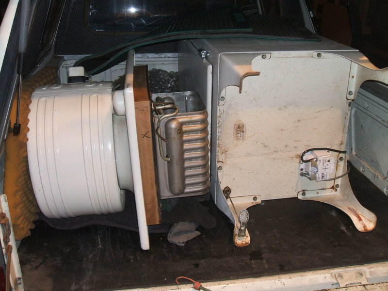
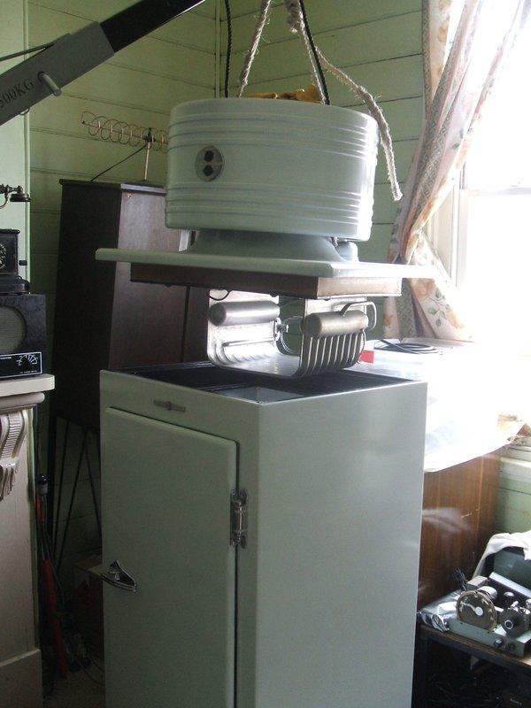
Just arrived home. The damage was now clear to see, as was the bodgie transformer installation.
Shortly after the completion of the CA-2-B15 project, I received a query about a CA-1-B15, as a result of my postings on the Flickr group. The bizarre thing was that this fridge was located only half an hour away from where I live. A monitor top in Australia is rare enough, but to have another so close to home was the last thing I expected.
CA-1-B15 Introduction.
For American readers, the CA-1-B15 is the same as the CA-1-B16, except
it is made for 50 cycle operation. This entails having a start relay and
control able to function correctly on the lower frequency. It essentially
means the contacts are beefed up to deal with increased current, when used
on 50 cycles. The compressor motor is satisfactory on both frequencies
as is. Of course, the cabinet light does not care about supply frequency.
For models sold in Australia, a stepdown transformer was supplied to provide
110V from the local 210-250V mains.
The CA-1 cooling unit is used with 5 cu. ft. cabinets. It uses 2.25
lbs of methyl formate as refrigerant and has a cooling capacity of 430
btu. Compressor is 1/8 hp.
High side float regulation is used to control refrigerant flow into
the "U" shaped flooded evaporator. The CA-2 unit is for 7 cu. ft. cabinets.
It has the same compressor, but with the larger evaporator has a cooling
capacity of 480 btu. There is also increased condenser area by means of
tubing encircling the underneath of the cabinet top. Its charge is 2.75
lbs of methyl formate.
Faulty CA-1.
The owner claimed that the fridge seemed to have a leak. The compressor
was working. Would I like to have a look and see about repairing it? Of
course I couldn't say no to that, especially as it was so close. So, I
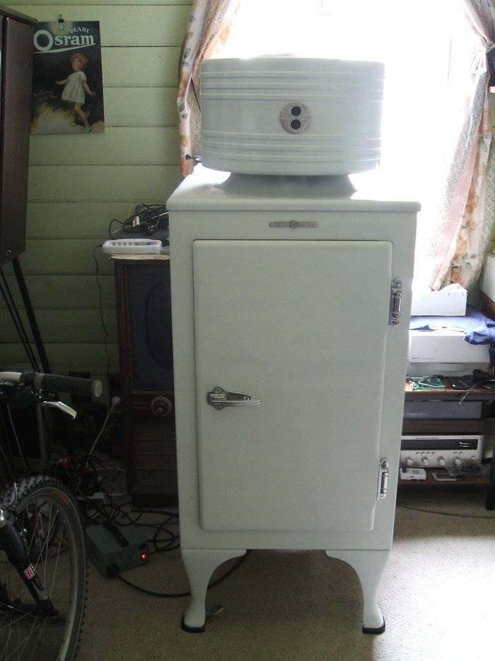
visited the owner and was greeted by a 1934 CA-1-B15. Cosmetically, it
looked not too bad. A quick look inside showed what looked like a crack
in the join of the low side tube. Perhaps it had leaked here? Out
of curiosity, I started up the compressor which sounded as it should -
quiet with no rattling. After about 20 seconds maybe, a loud hissing was
evident inside the cabinet.
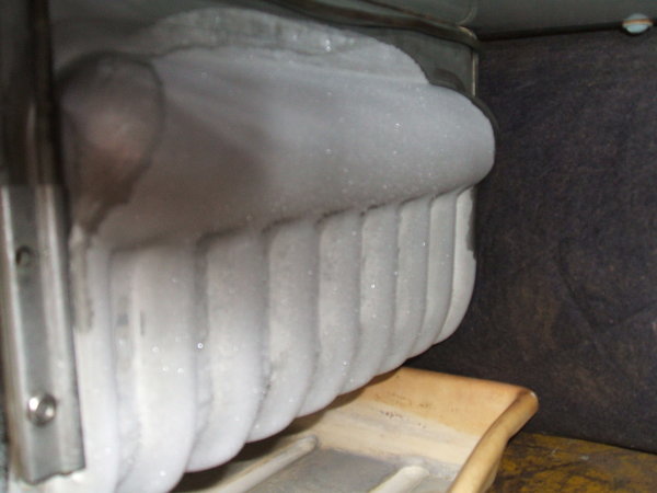
Opening the door resulted in a spray of methyl formate vapour. It was
fairly strong but certainly not unpleasant. Nevertheless, I shut the door
to avoid breathing any more in.
At this point, assuming it was just a cracked connection, I worked
out a quote of what it would cost. Despite the price of methyl formate,
and the time it would take, and given it would be a spare time job, they
seemed keen to proceed. But, given the amount of methyl formate that came
out, I decided to check further.
Broken High Side tube
I put my hand up the side of the evaporator and could feel something
loose. I was able to lift the cooling unit above the cabinet top by placing
my knee under the evaporator with my hand in between. This is when I realised
something was amiss - there was oil all over the evaporator. Lifting the
unit revealed the problem. The high side tube was torn off the evaporator.
To make things worse, it was torn off right at the side where it goes into
the header tank. No protruding stub that could be reconnected. This changed
everything because I didn't like the chances of reliably connecting a new
piece of tube to the stainless steel after that sort of damage. It would
add to the complexity of the repair.
By now the owners could see the problem, and that I could never guarantee
anything. I suggested that a later fridge using R12 than anyone could service
would be a better option. I suggested they have a think about what's involved
first before proceeding.
It's mine.
Then the lady of the house made me an offer I couldn't refuse. If I
paid them what it cost them would I want it? So, for $120 I ended up with
another monitor top, another CA.
The story of how they came to get it was that it was at an auction
house in the city along with a 1940's gas stove they also bought. The idea
was to create a kind of retro kitchen on the back patio that they could
use for entertaining. However, as I was soon to discover, at some point
the cooling unit had been mishandled. CA-2 deja vu all over again.
Just arrived home. The damage was now clear to see, as was the bodgie
transformer installation.
One obvious difference between the CA-1 and CA-2 is how much easier
it was to move. The 5 cu. ft. cabinet is lighter and smaller. It easily
fitted into the back of the ute without having to take the legs off.
To get the cooling unit off, we used two lengths of wood under either
side of the condenser and lifted it off the cabinet. The shorter evaporator
and shorter cabinet made this possible, whereas it would not be so easy
with the CA-2.
The damage.
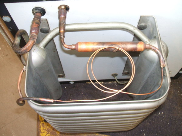
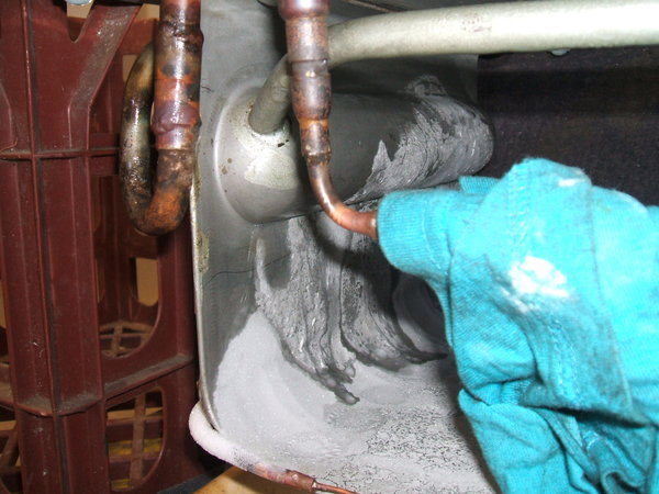
Once home I could have a clear look at the damage, and here I could
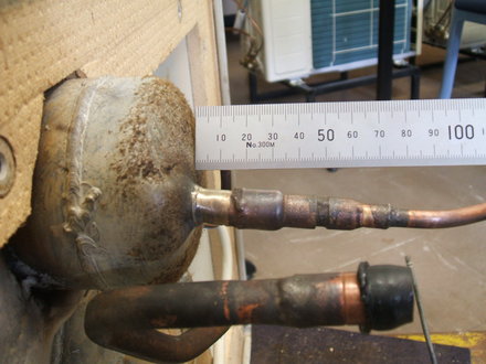
see a repair possible for the evaporator connection. The tubing was broken
off flush with the header tank. There was no damage to the surround, so
the header tank was still sealed. I could also see that the high side tube
inside the header tank was a perfect fit for the tube which comes out of
the high side float. All I would need to do is use this tubing and insert
it, say half an inch, into the header tank tube and resolder. With that
worry out of the way, I then noticed the float valve damage. The tube emerging
from the float chamber, which contains the valve seat was bent to one side
as well as suffering an indentation. I also noticed gouge marks on the
low side evaporator tube.
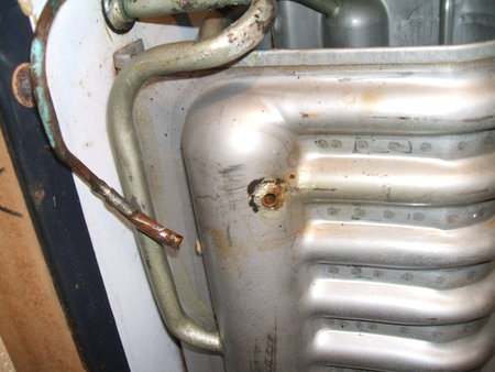
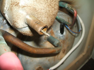
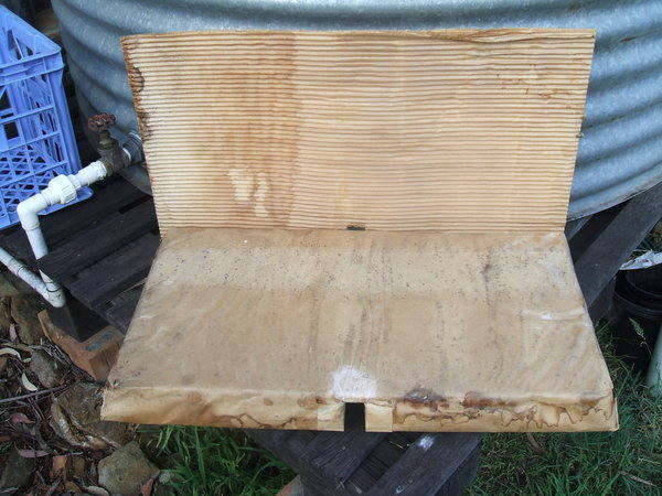
High side tube cleanly torn off the evaporator.
Looking at the cooling unit lying on its side next to the cabinet, I started to see the likely scenario of events. It appeared that whoever moved the fridge in the past did not know the top lifts off. It seems that the idea was to place it on its left side in the back of a truck/trailer etc. However, as it was tilted over, the top started to lift. Hingeing on the left side of the cooling unit, the right side lifted causing the high side tube and float seat to catch on the cabinet lip. Further support for this theory is the presence of a dent in the condenser on the left side.
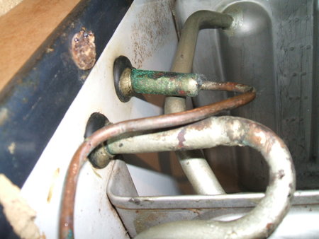
Float valve tube (made from "Everdur"- a low thermal conductivity
alloy) was bent which could affect needle and seat alignment. Not visible
here, but the tube was also partially crushed.
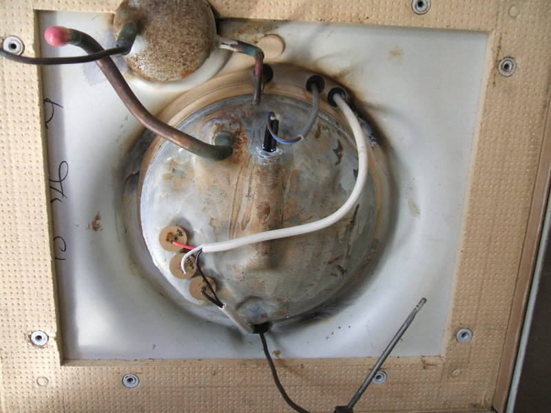
The transformer was interesting. This time it was mounted under the cabinet, but was modern. It had been attached by an assortment of self tapping screws. The connections were quite bodgie and not terribly safe. No cover was provided for the transformer or its connections. The wires were merely connected to the terminal blocks and left exposed. No cable clamping had been provided. Furthermore, the earth wire from the 240V mains lead had been cut off. This, plus the fact it was an auto transformer did not give a feeling of much safety. The 110V lead up to the light and compressor was original, and not surprisingly, in poor condition.
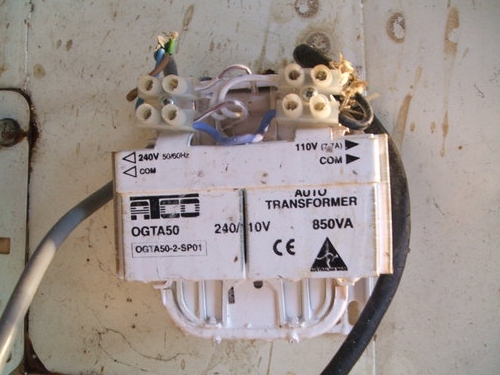
No attempt at covering the transformer or connections. Unbelievable
that the earth wire was cut off, especially as this is an auto transformer
which provides no isolation.
Restoration begins.
Having been through most of the learning curve from doing the CA-2
restoration, this one should be a lot quicker. In fact, it would be much
the same procedure given the similar damage. However, I was concerned about
the float valve. Given the "everdur" tube had been slightly crushed I feared
the seat might be out of alignment with the needle. That, and the realisation
that the needle and seat could be worn or sticking made me consider the
capillary conversion option. It would be a shame to refill it with methyl
formate only then to find out there were troubles.
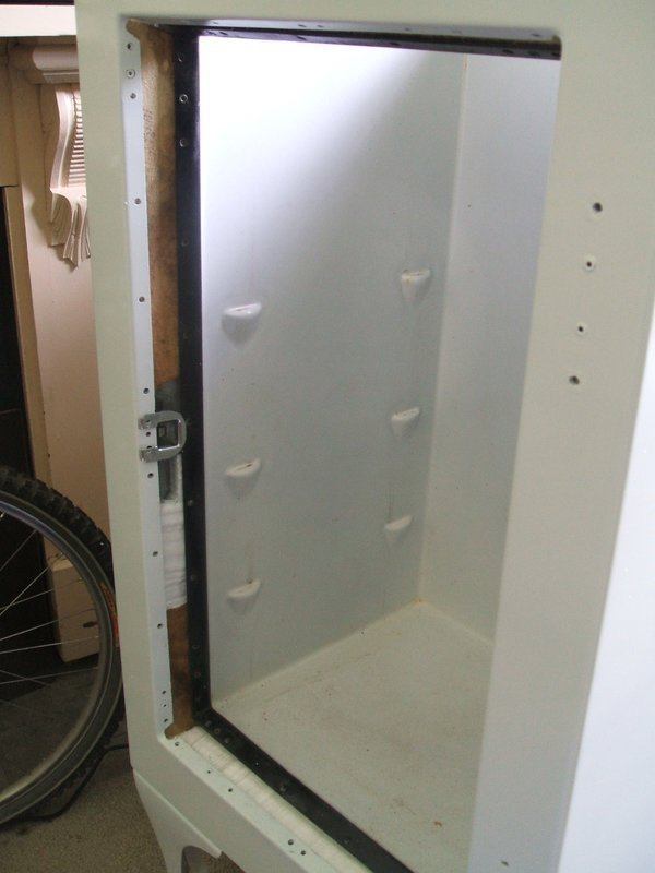
First thing was to get the cabinet top apart, so removed the evaporator
as per the CA-2. Inside was in much better condition. Although a rewire
was in order of course, I would not have to repaint the inside.
Surprisingly, the oil heater was good. It measured 950 ohms. I rewired
using 3 core flex like I did with the CA-2. Heatshrink tubing was used
to recreate the correct colour code.
Cooling unit rewired. A repaint was not necessary, but the compressor
to cabinet top seal was replaced with Silastic. While the rubber tape was
largely good, sections were deteriorating.
The GE lead seal on the relay box was still there, so we can assume it had not been opened since manufacture. However, the relay contacts inside were surprisingly pitted. Not like those for the CA-2.
Evaporator Repair.
This went to plan without any problems. As before, I temporarily soldered
Schrader connectors to the evaporator inlet and outlet for testing. I was
particularly pleased to find no blockage. Now I knew how freely the nitrogen
should flow through. The evaporator was left pressurised at 45psi for about
a month and showed no sign of leakage.
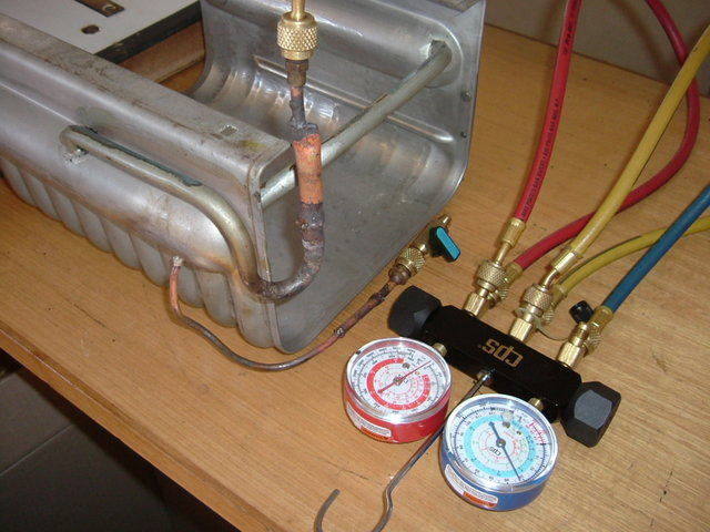
Evaporator was kept under pressure for a month. It did not leak.
Preparing for the capillary conversion.
Once I'd made the decision to go through with this, I prepared the
float valve. Bending the tube back was much harder than I thought - it
must have been subjected to quite a lot of force. Then the seat was cut
off. This was done 1.7" up the tubing because the dent in the tube might
prevent the seat being extracted. The needle was in excellent condition.
However, close inspection of the seat revealed some slot shaped wear at
opposite sides. So, I had definitely made the right decision to change
to a capillary.
Float seat removed from Evedur tube. This is necessary to disable
the float valve.
A 1/2" to 1/4" reducer was required to connect the Everdur tube to the modified filter drier. I found that the ordinary 15% silver solder worked perfectly here. To minimise the risk of burning the cabinet top insulation, the reducer was soldered on before the cabinet top plate was replaced.
1/4" tube soldered to outlet of float valve. Due to availability,
I used a 1/2" to 3/8" followed by a 3/8" to 1/4" reducer.
The filter drier needed modification as it is unknown how methyl formate
would react with the moisture absorbing pellets within. A hole was drilled
into the side and the pellets extracted. The hole was then sealed up with
a brass screw and silver solder. The filter has a coarse strainer at one
end, and a fine strainer at the other. This end is what feeds the capillary.
The filter is necessary because of the small diameter capillary tubing.
If any foreign particles blocked the tube it would be impossible to clear
out - unlike a float valve.
Given the work done to the cooling unit, and that it had been run open
to the atmosphere, such particles should be assumed to be present.
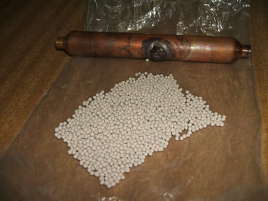
Pellets extracted from the filter drier and hole sealed up.
The cabinet top plate was cleaned up and cold galvanising paint applied
to the rust spots. New stainless steel cup head bolts were obtained for
the evaporator as the originals had the nuts rusted on, and had to be cut
off. As with the CA-2-B15, new washers were made from neoprene. With the
evaporator reattached, the top plate was ready to go back on. Prior to
doing this, the 1/2" joiner was soldered to the low side compressor tube.
It was found that the grommet for the float valve would not fit with the
reducer in place so had to be left out, with the intention of sealing the
gap with silicon or similar.
40" of .028" capillary tube was specified for the CA units, but due
to availability, I had to use .026". There are charts to convert between
different lengths and sizes which showed that for .026", I would need to
use 29".
To cut the capillary tube, I used a file to nick a groove all around
the circumference and then snapped it. An X-acto knife was then used to
ensure the bore was clear. Using pliers or side cutters is unsatisfactory
because the capillary will be crushed. The ends of the capillary need to
be poked in an inch so that no silver solder finds its way to the opening.
Nitrogen was run through from the charge valve whilst soldering all
the parts of the capillary conversion. Before the final connection, where
the capillary enters the high side tube, I checked for a flow of nitrogen
at the end of the capillary.
Capillary conversion complete.
Once the final connection was made, the cooling unit was vacuumed, then pressurised with 45psi of nitrogen and left for a week. No leaks were evident, so the unit was vacuumed again with the heater on, and the parts of the cooling unit heated by means of a heat gun. A second vacuum was performed until the pressure was down to 29.870". One problem evident is the charge valve adaptor is prone to leaking. I made a lead washer to seal against the charge valve which improved the sealing, compared to the supplied copper washers.
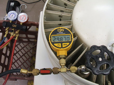
A digital vacrometer is far more accurate than the mechanical gauge
and shows leakage at low levels which the analog gauge cannot.
Refilling.
On the day, further vacuuming was done for several hours. The pressure
stabilised at 29.893". As with the CA-2, I used the plastic funnel tightly
fitted over the charge valve to pour in the methyl formate.
First, I poured in about .45lbs, and ran the compressor for about a
minute to get it circulated. Already, the bottom of the evaporator was
cooling. After a short rest, I added another .45lbs, and the area of cold
increased. In the end I had added 1.29lbs which got the frost line to the
top of the header tanks. This is 57% of the normal charge. I also added
a likely looking amount of compressor oil (mineral type 4GS). This
was also done via the plastic funnel. An interesting thing showed up here.
The oil sits on top of the methyl formate and does not mix. It's also much
more dense of course and the charge screw needed to be opened a little
further for it to be sucked in.
Performance.
Immediately, there was a clear difference between this cooling unit
and that of the CA-2 which still has the float valve. Not only did the
evaporator frost much faster, it also got much colder.
Almost a month after filling, there was still no evidence of non condensable
gases. This would indicate no leaks. There is however and interesting variation
in frost level in that it sinks on the right side tank after the compressor
has run for a few minutes. However, I assumed that to be lack of full charge.
My reason for not putting in full charge at this stage is because the unit
was not operating in the cabinet, so conditions are not as they normally
would be. It could be possible to overfill. Once I had the cooling unit
in the cabinet, then charge level can be optimised. Even at less than optimum
charge, performance is far superior to the CA-2 with float valve.
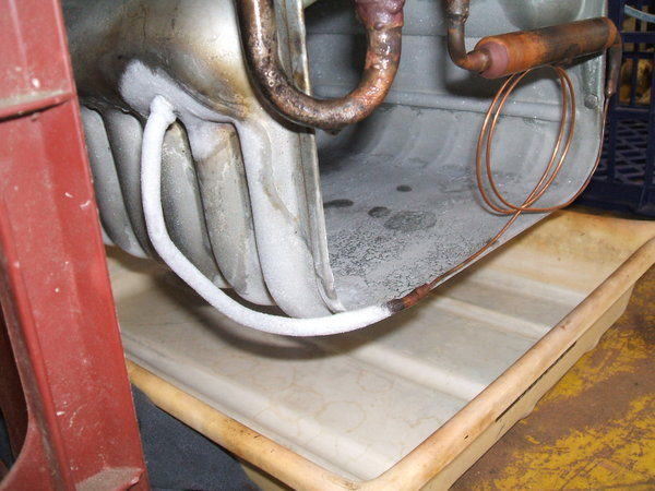
Frosting commences at the end of the capillary tube.
Success of the capillary conversion is seen here. This amount of
frost accumulated in only about 10 minutes.
Frost line with only 57% of recommended charge. The rag around the
filter and capillary was an experiment to see if the cool air coming off
the evaporator affected the frost line.
The Cabinet.
Despite the good appearance externally,
several things made me suspicious about its real condition. The Textolite
strip at the bottom of the door frame was warped. There were also a few
pinholes in the cabinet, and a rust stain beneath the door opening. When
I unscrewed the transformer, the screws were wet. First thing was to remove
the Textolite strips. And here I struck problems. Most of the screws were
extremely difficult to remove. I removed enough to see under the Textolite,
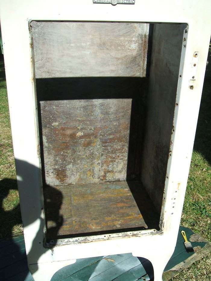
and the horror was revealed. All the insulation was wet and had disintegrated.
Obviously, the inner liner was going to have to come out. With a lot of
persistance, most of the screws came out. The golden rule here is to use
a very good fitting screwdriver, otherwise the heads will be chewed as
they are quite shallow. I used a lot of CRC2-26 to try and free up the
rust. By the end, three screws were too damaged and I had to drill their
heads off. The thread is very close to 4 mm, but is obviously something
else. It should be possible to retap and install similar 4 mm screws.
Once all the Textolite strips were off, it was very easy to lift out
the liner and insulation. Fortunately, the liner had only minor surface
rust. There was no way the insulation could be re used, even if it was
dried out.
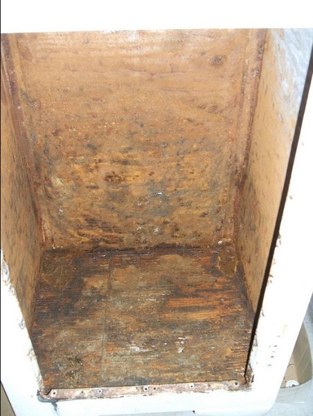
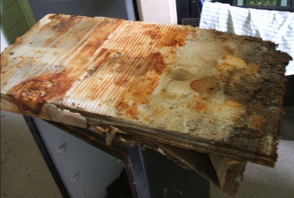
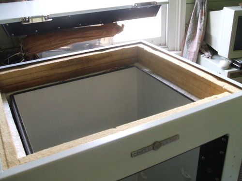
Years of moisture inside the cabinet had resulted in extensive rust
and ruined insulation.
The cabinet rust was quite extensive, but looked much better after a considerable amount of wire brushing and scraping. The areas around where the legs screw in was covered in wax, so this escaped damage. Fortunately, the rust had not affected the cabinet strength. It goes to show, a good looking cabinet could be hiding something like this. And to think the previous owners were content with simply cleaning the outside of the cabinet...
Cabinet Restoration Begins.
I had heard about products like KBS and POR-15 as a method of treating
the rust, from the Flickr group, and in the Model T Ford club. Given the
severity of the rust, ordinary rust converter seemed like it would be inadequate.
So, I studied both KBS and POR-15 and came to the conclusion they were
much the same thing. One story was that the chemist who created POR-15
later created KBS.
I decided on the KBS treatment as it was Australian and I could easily
get it.
The treatment consists of three stages; first a water based cleaner
(interesting idea with all the rust!), secondly what appears to be some
kind of rust converter, and thirdly, a thick sealer.
This is after the water based cleaner and rust converter was applied.
There are actually a few spots of shiny metal!
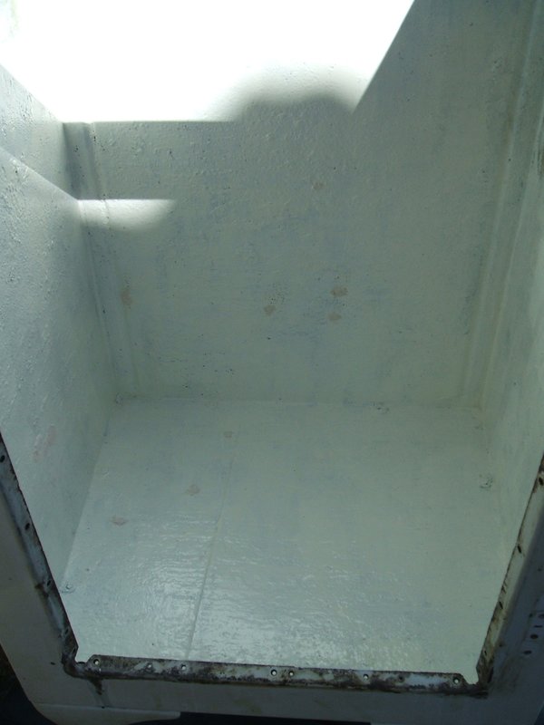
After the second stage (rust converter?) and sealer, now ready for
painting. You can see the spots of body filler used to repair the holes.
Normally, I am very sceptical of rust treatment, but the KBS really
seemed to work. Much to my surprise, the water based cleaner made a huge
difference to the inside of the cabinet. It looked a whole lot better,
and there was even shiny metal visible in parts. After cleaning and drying,
the next stage was applied...something by the name of "Rust Blast". This
was then rinsed off leaving a coating over the rust.
Finally, the third stage was applied. This is a very thick flexible
sealer that really sticks. I had to thin it before being able to brush
it properly.
Once done, the improvement was like the difference between night and
day. All the holes were filled with ordinary car body filler. This is important
to prevent the entry of moisture.
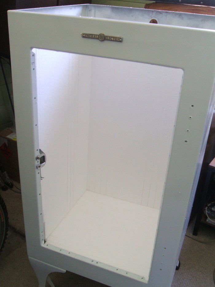
Then the usual coat of primer and three coats of white appliance enamel
were sprayed on. At this point, the outer cabinet was now complete.
Painting the cabinet.
As with the CA-2, I used aerosol cans to spray with. One coat of primer
was used, followed by three of white appliance enamel. This made a huge
improvement in appearance, and now the question of insulation needed to
be dealt with.
Insulation.
As the original Thermocraft insulation was damaged, some alternative
had to be found. I considered expanding spray foam, and while this would
work, I didn't like the permanency of it. It would certainly seal out moisture
and even provide a bit of extra strength to the cabinet, but the liner
would be stuck in permanently unless isolated by a plastic sheet. Trying
to keep to the original design, I decided to use styrofoam sheets, 60 mm
thick as intended for under floor insulation. As it turned out, this was
just the right thickness for the side pieces. The bottom piece had to be
raised up with two layers of 10 mm thick foam pieces so that the inner
liner was supported in the correct position.
Painted and new foam insulation installed.
The inner liner was in good condition. It needed only a few touch ups
with black paint. However, the wiring had to be replaced. Dismantling the
light socket resulted in breaking a screw, but fortunately I had a suitable
replacement. I got the impression that the light socket, like the inlet
socket, and door switch were never meant to be rewired. All the connections
were sealed. Hence, the use of the junction box.
For the inlet socket and switch, I cut off the old fabric covered wire
fairly close to the body and soldered on new wire, covering the join with
heatshrink tubing. Unfortunately, the junction box screw was rusted in
position so was not reusable without a lot of work. With the new wiring,
it wasn't required anyway. The inlet socket and light socket were sealed
with Silastic to prevent air entry.
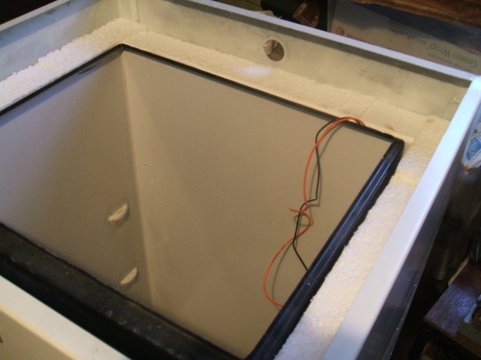
Liner in position and light socket wires ready to be connected.
Liner needs to be supported not only by one 60 mm thickness of the
foam, but by two 10 mm thicknesses also. In this position, the Textolite
lines up perfectly.
Original insulation blocks were in good condition so were re used.
Cutting the foam.
In the end I was very impressed with the foam. It fitted well, and
it was obvious how much better than the old Thermocraft (corrugated cardboard)
it would be.
Do not use a saw to cut it! I initially did this but the mess was unbelievable.
Tiny pieces of styrofoam went everywhere - and stuck to everything. I tried
a hot wire cutter and this was not only mess free, but considerably faster
and gave a better edge. My hot wire cutter consisted of a short piece of
nichrome wire obtained from a burnt out jug element. It was connected to
a 14V transformer which was in turn connected to a variac. This was set
so the wire was just below red heat. The wire itself was just supported
in alligator clips.
With the hot wire cutter, it was easy to make the unusual shapes required
for the front of the cabinet that go beside the Textolite strips, particularly
around the pedal mechanism.
Textolite.
I simply cleaned the strips with a scouring pad and water, leaving
them in the sun to dry. New screws were purchased from Antique Appliances.
The new screws were said to be 10-32 size. This is not quite the same as
the original, which appears to be 10-30. Nevertheless they do go in, even
though they're on the tight side. One nice feature with the replacements
is that they have a much thicker head which makes it a lot easier to screw
them in with the screwdriver slipping out.
Pedal mechanism.
The wire rods and stuffing box were cleaned, which involved grinding
the rust off, and then sprayed with Galmet cold galvanising paint. The
stuffing box is in very poor condition and ultimately I may replace it
with a rubber bellows.
Cabinet top seal.
Here I could have reused the original No-ox-id cloth, but would have
required a bit of work sealing the joins and tears. Besides, one problem
with it as that the corners catch against the cooling unit when it is lowered
in. So, I decided to try duct tape. I was quite impressed with this once
completed, and the sharp defined corners wouldn't catch on the cooling
unit. Besides that, there was no doubt a better air seal was provided.
To get the width required several overlapping strips. The tape I used was
48 mm width.
The final part of the seal was a new neoprene strip to bear against
the cooling unit.
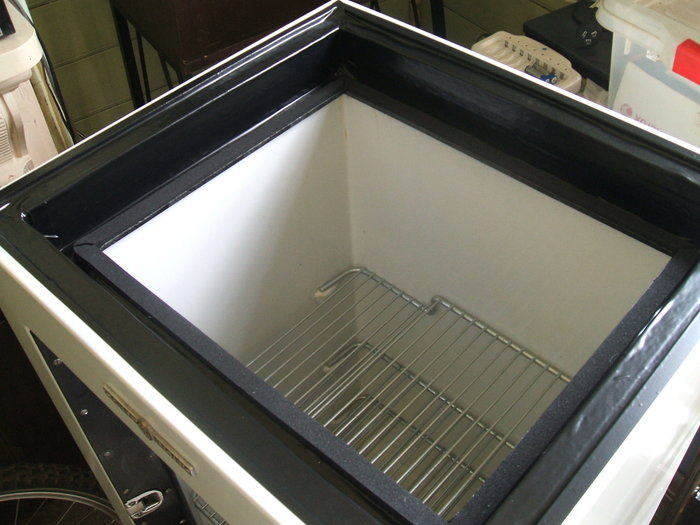
Cabinet now complete with new top seal in place.
The door.
This was an easy restoration as all the Textolite screws came out without
a huge amount of difficulty. The insulation was good, so it got reused.
As with the cabinet, the door was primed and given three coats of white
appliance enamel. The latch was lubricated with waterproof grease. The
original gasket crumbled away so I made a new one from thin cardboard.
Of course the door seal had to be replaced so a new one was ordered from
Don at Rusty Metal Rescue. It is important to note that the hinges should
be tightened on the door after they are screwed to the cabinet. This is
so they are set to suit the thickness of the seal. I was caught out by
this when the door was difficult to close after installing the new seal.
The hinges and latch were polished with Brasso.
The Thermocraft insulation for the door was in good condition. It
consists of layers of corrugated cardboard wrapped in brown paper.
Installing the cooling unit.
As with the CA-2-B15, I used an engine hoist. This makes lining up
the cooling unit against the cabinet very easy before finally lowering
it in. It would be extremely difficult otherwise, especially as there's
not much room besides the fragile tubing. As expected, the duct tape seal
also added to the ease of lowering it in. No corners to catch on the cooling
unit.
Finally lowering the cooling unit in. The tubing must be kept clear
of the inner liner edges. Unfortunately, many Monitor Tops get damaged
at this point when the tubing catches and is ripped off or crushed.
After eight months of work, the X5 cabinet and CA-1-B15 cooling unit were back together.
All the hard work done. Now for the easy stuff!
Final work to be done.
A friend had provided me with several metres of black two core flex
with 1.5 mm conductors. With this I could make up an authentic power cable
that looked exactly like the original.
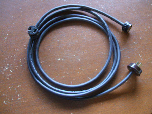
The feed through socket is for the cabinet light.
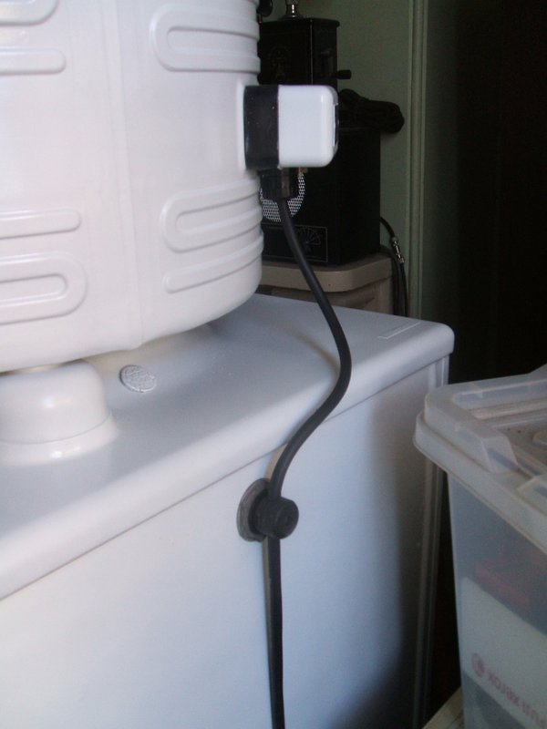
Wiring complete and like new.
As I got this fridge, there was a 15W 240V bulb in the cabinet. Obviously in the past the original had blown, and the owner not realising it was 120V, or not being sufficiently motivated to find a 120V replacement, had used an ordinary 240V bulb. It gives an dull orange light on 120V. While 120V bulbs have been sold in Australia, due to their rarity they have been expensive. Also, in more recent years, the available wattages have been limited. So, I simply bought a carton of 40x 15W 120V bulbs from the U.S. Even with postage, total cost was still less than they would have cost here.
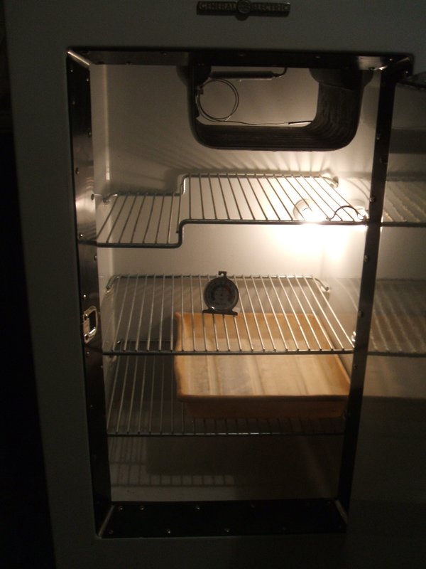
Inside the cabinet with new 15W light bulb. The photographic developing
tray is a temporary substitute for the glass chiller dish.
Finalising the refrigerant charge.
Now I was able to test run the machine. Even with only 57% of the refrigerant
charge (1.29 lbs), the cabinet came down to temperature in about 1.5 hours.
In the cabinet, out of any air draughts, the evaporator frost was more
even. However, it was obvious that more needed to be added. While the fridge
could be used as it was, the cycling times would no doubt not be as good
as possible, and also with the level below the skimmer in the right side
header tank, I was concerned about oil eventually building up in the evaporator.
The CA-1 is intended to be charged with 2.25 lbs of methly formate.
However, when the float valve is replaced with a capillary tube, the optimum
charge is less. This had to be found by experiment, and is why I did not
put in the expected amount while the machine was outside the cabinet. Operating
it this way does not give an accurate frost line.
With the cooling unit now installed, it was time to add more methyl
formate. As before, I cooled the bottles just to minimise any internal
pressure. The orange funnel was placed on the charge valve and more added.
At 1.795 lbs all up (80% of full charge), it was looking very good, with
frost level stabilising almost halfway up the right header tank. It seemed
effortless for the cooling unit to bring the cabinet down to freezing point.
When adding refrigerant, adequate time must be given for the frost
line to stabilise.
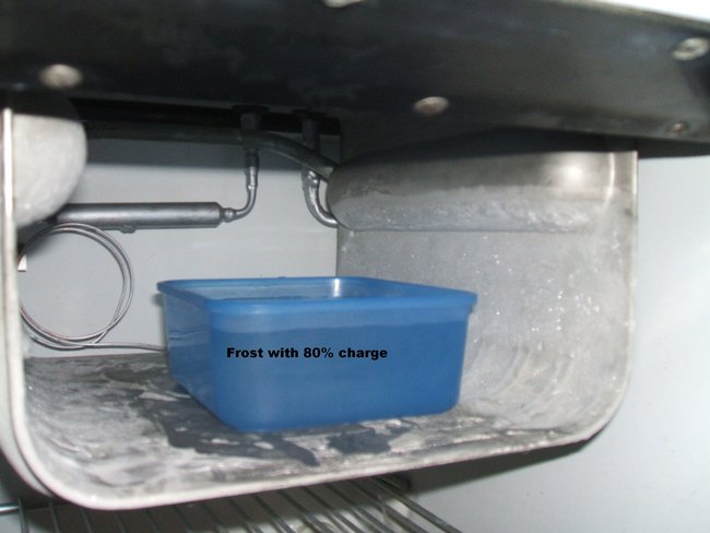
With 80% charge, and under load, the frost reached halfway up the
header tank.
With 80% charge, the frost line had evened out and covered the full
length of the right header tank. Performance was very good, with 2 min.
15 sec. run times and 12 min. off time. However, I felt that the frost
line should be higher, about 3/4 of the way up the header tank, under load.
So, I added another 10%, now making the full charge 2.035 lbs.
This did get the frost to the required height under load.
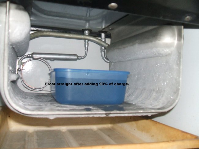
The new thinner layer of frost can just be seen about 1/4" above
the original thicker lever where it was at 80%.
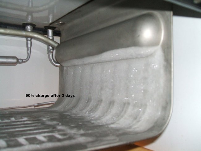
After stabilising, the frost line is still in the same place as
when there was 80% charge.
Cycling times seemed quite a lot worse after I added the extra 10%.
Now, the run time was 2 min. 30 sec. and the off time about 10 mins. However,
upon turning the thermostat down three divisions, and removing the ice
tray, it was vastly improved. Off times were now 16 mins. 19 sec. This
was actually what I was looking for.
So, it seems the optimum charge is between 80 and 90% of the original
specified, when a capillary conversion is done to the CA machines.
It appears that overcharging the CA does not show up by frost level,
with the excess presumably remaining in the compressor dome. The rule of
thumb seems to be therefore, to fill until the frost line evens out. A
small amount may then be added to get the frost line 3/4 of the way up
the right header tank when the machine is under load. Any excess will simply
reduce off times, thus increasing average power consumption.
Restoration Complete.
A week's testing ensured the excellent cycling times were not some
sort of fluke. Once the cabinet is down to temperature, under no load,
the condenser runs cold, as does the float valve, with only slight warmth
on top of the compressor dome.
I have been delighted with the performance. At no time has this fridge
given any trouble. Nearly six months on from the first filling, it has
still not needed an NCG purge.
There is no doubt that all CA machines should have a capillary conversion.
So far, from my CA-1 and CA-2 experiences, and those of others who have
restored these models, all needle and seat assemblies have been worn. It
appears the methyl formate either erodes the seats by chemical reaction
or just by flow, and in modern times prevents CA machines operating to
their full potential.
Installing a capillary conversion eliminates this problem permanently.
Postscript - 18 Months after restoration.
Performance of the CA-1 has been nothing short of sensational. It has
proven to be a reliable and dependable refrigerator with excellent cooling
performance. Even at the height of summer with a few 36 degree C days,
cabinet temperature is easily maintained. It took 18 months to require
an NCG purge. This is an excellent record, given the machine had been open
for six months and the oil would have absorbed some moisture.
In retrospect, the capillary tube should really be 44.5" long in view
of the lower compressor RPM on 50 cycles. However, I was unaware of this
at the time I did the conversion. In fact, to my knowledge, this is the
second known CA unit to be converted to use a capillary tube. However,
given the excellent performance, I am happy to leave it as is..
The performance of the cabinet insulation has been a welcome surprise.
With the compressor switched off during defrost (23 hours before it automatically
switched back on), the cabinet temperature increased by only 6 degrees
F.
24th August 2013:Here's where
I'm up to so far with the X5 cabinet:
drive.google.com/drive/folders/0B8_jm7K-ahMabm9VNzVjTHVjMVE
The rusty cabinet - the result of years
of wet insulation.
Cleaned and rust converted. I'm using
KBS rust treatment which is very similar to POR-15. Much to my surprise,
some shiny metal was visible after this part of the process.
Holes filled, KBS top coat applied, and
then primer and a coat of white epoxy enamel. Unfortunately it will never
look better than this because of the severity of the rust, but it is now
sealed and stabilised. Next is to do the much easier cosmetic restoration
for the outside.
15th September 2013: The
outside of the cabinet is now finished; one coat of primer and three of
white appliance enamel as per the CA-2.
Now, I'm up to the door. And what a pain
it is getting all the Textolite screws out. Easier than the cabinet because
of less rust, but nevertheless more blisters on the hands and chewed screw
heads. I only had to drill one out. Interestingly, the screw strips on
the back panel of the door are not held in place by rivets as they are
everywhere else. So, upon reassembly, the Textolite strips have to be screwed
to the inside panel first. Internally, the door isn't not too bad. There
has been a small amount of moisture in the door, but only light rust along
the bottom inside. The back panel (porcelain finish) is good and only needed
a little touching up. The insulation survived, so will probably re use
it. Restoration of the door is just a simple sand and paint job, but have
to replace the cork latch seal as it disintegrated.
16th September 2013: All
the brass rivets are slightly loose so the screw strips can be lined up
before tightening, except for those on the back of the door, which have
none - 3 are still attached in the above pic. I'll just reassemble in reverse;
i.e. put the textolite on the back panel first, then sit the insulation
in there and finally screw on the front panel. Just as well I've ordered
more screws than I thought I needed for the cabinet. By the way, Textolite
smells exactly like bakelite when you drill it.
To avoid getting anything out of square,
I'll just put in all the Textolite strips loosely then tighten them. The
door and cabinet are actually still quite strong with nothing inside them.
4th October 2013: Restoring
this cabinet is as tedious as restoring a vintage car - there's a lot in
common. Every part of this cabinet, except the legs has needed attention.
I've had to remove the screw strips because of the rust on the other side.
Fortunately, it is possible to reuse the rivets. I painted the screw strips
with galvanising paint. The light socket needed the wires replaced, so
I've done that, breaking a screw in the process. It's all back together
and back in the cabinet. I used Silastic to replace its seal against the
cabinet. The junction box cover screw is rusted in and can't get it out.
Anyway, I don't really need the junction box - the wires can go straight
to where they need to go.
The door is back together with original
insulation. I put anti seize compound on all the Textolite screws. Today
I received the replacement screws from Antique Appliances - very impressed
with them.
For the cabinet insulation, I'm using
60mm thick polystyrene foam sheets, sold for under floor insulation. I've
had to pack it up in parts with 10mm sheets to get the right thickness.
Cutting this stuff is best done with a hot wire - I used a saw at first
and the mess was unbelievable; little pieces all through the house sticking
to everything.
Finally, it is starting to resemble something.
I just have to cut the pieces for around the door frame. For the top seal,
I'll be using duct tape to replace the No-ox-id cloth.
5th October 2013: 4 Oct 2013
at 20:58 ChrisJ said:
I didn't realize antique appliances had
new screws for the strips?
Are they bronze like the originals?
Yes, they're 20 cents each and a perfect
fit. Their site says they're stainless steel. I think they're better than
the original because the heads are thicker giving a deeper screwdriver
slot. One of the problems with the originals is that it's so easy to ruin
the heads if the screws are the slightest bit rusted in
5th October 2013: 5 Oct 2013
at 08:34 allan said:
That really looks good! Did you have to
do anything to the inner tub? It looks good around the top
Not a lot really, just a light wire brush
and black epoxy spray around the upper edge. Actually it was in pretty
good condition to start with which is what really deceived me. If I had
known the inside of the cabinet was like it was I would have started work
on it a long time ago so it would have been ready when I'd finished the
cooling unit.
The inner liner, despite being pressed
against all the wet cardboard had no real rust at all, just a few posts
of surface rust I could wipe off with a scouring pad. The porcelain coating
seems to be a most effective rust barrier.
So, despite appearances, it seems that
all cabinets need to be examined inside, no matter how good they look from
the outside. The freshly painted monitor tops on ebay could easily be full
of wet insulation and no one would know until the rust holes start appearing,
or as I saw with a CG once, the cabinet starts collapsing.
20th October 2013: Now the
top seal is complete. I used several overlapping strips of duct tape on
each side. This moulds to the cabinet shape much better than the No-ox-id
cloth and should eliminate the problem of the cooling unit catching and
tearing the corners when lowered in.
I'm waiting on a door seal from Don, and
once I get that, the cabinet is complete. I just have to search in my light
bulb collection this afternoon for something suitable, otherwise put in
an ebay order.
I finished the cooling unit painting this
morning. Conditions were ideal with temp in the high 20's (C) and low humidity.
By the time I get the door seal it will be dry enough to put on the cabinet.
20th October 2013: Yes, I'm
expecting to add much more refrigerant than I first thought. I'll bring
home the scales to measure exactly how much eventually went in.
I suspect you're right about the inner
top seal - after all the gaps in the Textolite are going to allow the internal
cabinet moisture inside anyway. I think what really counts is the outer
top seal, and the door seal. With both those sealed, nothing from the outside
world can get in.
One thing I am curious about is what about
the door handle? That doesn't appear to be sealed. Moisture could enter
through there, through the door and into the cooling compartment.
21st October 2013: I made a cardboard gasket for the door handle since I had no cork or neoprene thin enough. I figure that any leakage there is going to be insignificant given the handle leaks anyway, but I think you're right, they just accepted it. It would actually be interesting to pressurise a cabinet and just see where all the leaks are.
21st October 2013: I couldn't
find any suitable light bulbs so I bought these
www.ebay.com/itm/Philips-15-Watt-Incandescent-bulbs-20-Packs-Of-2-/251359432277
Even with the shipping cost, the price
per bulb actually works out slightly cheaper than if I could get them here.
So, I 'll have spares for the CA-2 as well.
28th October 2013: The cabinet
is now finished. I attached Don's door seal with silastic instead of contact
cement (which I'd used on the CA-2). I found this easier and it's easy
to trim off any excess once it's dry. One interesting thing I found was
the thickness of this seal prevents an easy closure of the door. It's on
the hinge side where this is noticeable. I have read comments around the
internet from others who've experienced this, but didn't have the problem
with the CA-2. It's a minor issue, and I'm hoping the seal will soften
into the new shape over time. If not, it's easy to make spacers up for
the hinges.
The shelves were nickel plated earlier
this year when I had the CA-2 ones done. And of course, there's a new set
of foot pads. Hopefully, next weekend I can lower the cooling unit into
it and start testing.
See next lot of forum postings here
4th November 2013: After
eight months, the CA-1 cooling unit has been reunited with its X5 cabinet.
I was really pleased with the duct tape replacement for the No-ox-id cloth.
A very easy drop in without getting caught
on the corners. As with the CA-2, I used the engine hoist to lift the cooling
unit:
drive.google.com/open?id=0B8_jm7K-ahMaOXdhRXdCYUQxRjg
drive.google.com/open?id=0B8_jm7K-ahMaREMxaDNGZHBwWnc
It makes it so easy to line everything
up before the final drop.
drive.google.com/open?id=0B8_jm7K-ahMaTEtLYVIwU0x5aU0
And here it is after all that work.
Turning it on was a total anti climax.
It just works. No annoying blockages or strange fluctuations that plagued
the CA-2.
One interesting thing I have noticed is
that the heater doesn't seem very critical with this machine. I've never
had to heat it for half a day before running it.
Whether that's because of the capillary
conversion, or the smaller evaporator meaning the compressor is under less
load, I don't know yet. It quietens down in a few minutes from a cold start.
So quiet I can't tell if its running unless I get very close to it.
As I expected, the frost line is much more even with it inside the cabinet, and no draughts of air. In fact, at present it looks like I mightn't have to add as much refrigerant as I first thought. It's still on 57% charge. I could leave it running that way because even on #1, the cabinet temp is 39F. My only concern would be that with an excessively low refrigerant level, oil could build up in the evaporator because it would be below the skimmer.
Anyway, next step is the long term testing and refrigerant level optimisation. I have a feeling that foam insulation might just be going into the CA-2 if performance of the CA-1 is anything to go by so far.
5th November 2013: Here's
some more pics. The light bulbs arrived yesterday so I can give a view
inside the cabinet.
drive.google.com/open?id=0B8_jm7K-ahMaRFh3dmtITmdCZk0
drive.google.com/open?id=0B8_jm7K-ahMacXBfc1ljY2VxU0E
And here's the area of interest. Remember
there's only 57% charge of methyl formate.
drive.google.com/open?id=0B8_jm7K-ahMaWk9RSmRXYlQ2M3c
The height of the frost is right, but needs
to be widened out more.
drive.google.com/open?id=0B8_jm7K-ahMaaUlYWkltelpad1E
The fridge had only been running about
5 hours with the door shut, so not much moisture to show the frost, but
you can see the dark grey area on the right side.
drive.google.com/open?id=0B8_jm7K-ahMab2oxdnBqNnhOQW8
Notice the even level across the bottom
of the right header tank.
Even without the correct amount of refrigerant,
cooling is impressive. It only took 1.5hrs to get the cabinet from room
temp to 39F. In 12 hours it was down to 34F. If the two minute run times
are anything to go by, I think I might be on a winner with this one.