Quickly and easily test the viability of unknown coils.
Quickly and easily test the viability of unknown coils.
Model T Ford enthusiasts who rebuild ignition
coils may be interested in this handy pocket size tester. Within a few
seconds, it will show if the secondary coil winding is in good order, and
that the capacitor is of the correct value.
This is useful when presented with a collection
of coils. Which ones are worth rebuilding? This tester will save the annoyance
of rebuilding a coil, only to find it erratically fires because of a secondary
coil failure. This not as uncommon as one may think. I have encountered
it several times during coil rebuilding. The secondary winding is thousands
of turns of very fine gauge wire. It doesn't take much to damage it. Physical
damage can occur when digging out the tar to replace the capacitor. Electrically,
the winding might also be damaged if the coil is operated without a spark
plug, and part of the winding is burned away through internal arcing. And
of course, there is plain old corrosion of the wire. Moisture and acids
from the paper insulation can corrode the copper, particularly where the
enamelling process was imperfect.
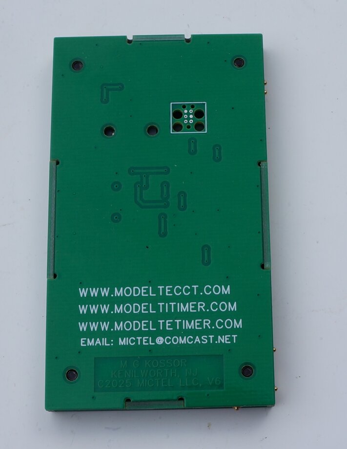
Rear view of the tester. The capacitor testing contacts are at bottom
and lower right.
Even if you are not into rebuilding coils, this tester still has a place for the Model T owner. It can of course be used to test the coils already in your own car. If you suspect an ignition problem, this tester can be part of the process of fault elimination. Many things can cause ignition problems, including faulty key switch contacts, worn or misadjusted timer, coils out of adjustment, fouled spark plugs, and so on. With this tester, you can confirm that the coil secondary is not open circuit, and that the capacitor is within tolerance, before moving onto other things.
A trap can be a coil which appears to fire normally, but the secondary winding is actually open circuit. Initially, the voltage is high enough to arc across the break in the wire, and the spark plug produces a normal spark. One might be led to believe all is well, but what is actually happening is that over time, that arc slowly burns away the wire, increasing the gap. Eventually, there's very little left for the spark plug, which then fires erratically, and then not at all. Inside the coil, the insulation becomes stressed, since the high voltage is trying to find the easiest path to complete the circuit. This it does by breaking down the enamel insulation of the copper wire, and the paper insulation between each layer of the winding. It is for this reason, an ignition coil should not be operated into no load. Short circuit the output, if you must run it without a spark plug.
Background to the Tester.
The tester was designed by Mike Kossor,
who I've mentioned in other articles on this site. Mike produces the well
known E-Timer, I-Timer, and ECCT coil tester. These products have been
well received in the Model T world, because they are well designed and
meet all their claims. I was therefore very interested to take the opportunity
of testing Mike's new tester.
Defective Windings.
The Coil Beeper was intended for those
purchasing coils from swap meets and the like, to identify (and thus avoid)
those with defective secondary windings. The device was held against the
side of the coil, touching the two secondary winding contacts. If it buzzed,
the prospective purchaser knew that the winding was probably OK. I say
"probably", because resistance type testers will not show adjacent shorted
turns. For this, something like a Q meter is necessary. Fortunately, shorted
turns are extremely rare; much less so than an open circuit secondary.
The primary winding is only a couple of hundred turns of thicker gauge wire, and is exposed to considerably less voltage (about 300V at the high voltage end). The chance of failure is so remote that it is generally not worth the extra complexity of testing. The only instances where I have encountered what looked like an open circuit primary, is where the enamel was not completely removed, prior to soldering the coil box terminal.
Improved Tester.
While continuity testing with a simple
battery and buzzer circuit will show if a coil is open circuit, it will
not
show if there is a short circuit, or if there is a high resistance in the
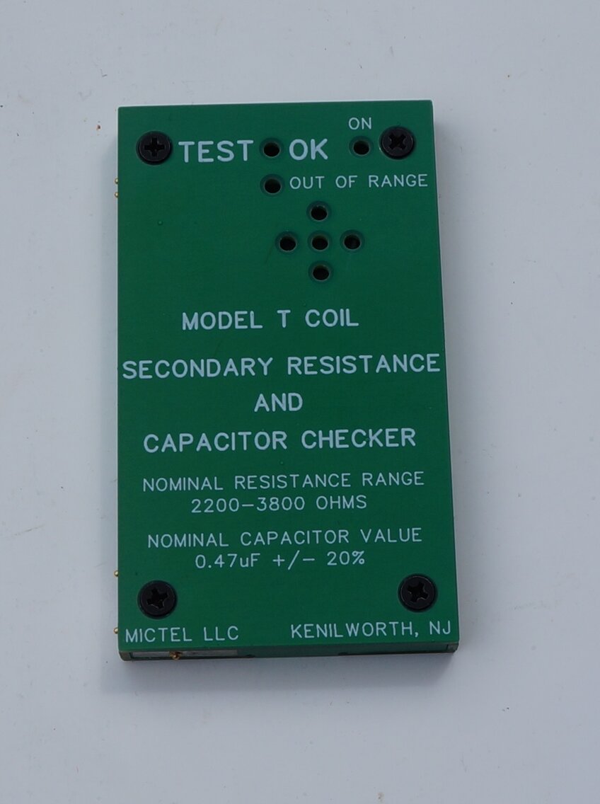
winding. This is where the new "Model T Coil Secondary Resistance and Capacitor
Checker" comes in.
Instead of a simple continuity test, users get an indication if the resistance of the coil is within the correct range. This identifies if the coil contains obvious short circuits (typically from insulation breakdown), or the resistance is too high (for example, from corrosion in the copper wire - likely to soon go open circuit).
Additionally, the tester will give an indication
if the coil capacitor is within a satisfactory range of values. Sometimes
coils are rebuilt with the wrong value of capacitor, or the capacitor is
actually open or short circuit.
Original paper capacitors should be replaced
as a matter of course when rebuilding coils. It is true that plenty of
coils are still operating satisfactorily with originals, but this is not
recommended for long term reliability, and optimum operation of the ignition
system.
As such, I would regard the resistance
test being the more important feature of this tester. Nevertheless, the
capacitor tester will give an insight into what to expect.
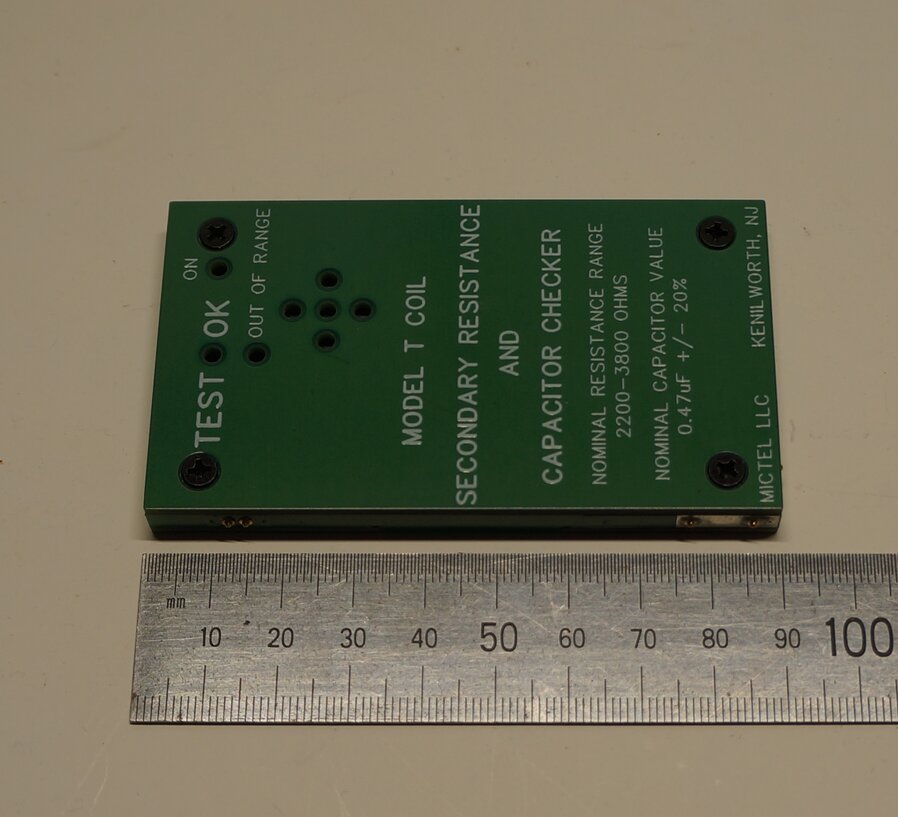
Pocket size is convenient for swap meets.
Evaluating the Tester.
The first thing that struck me was the
well thought out design. It's made entirely from PCB (printed circuit board)
material, and is only 8mm thick, with all the circuitry contained inside.
The length is 90mm and width is 50mm (about the size of a credit card).
It will fit into the smallest pocket.
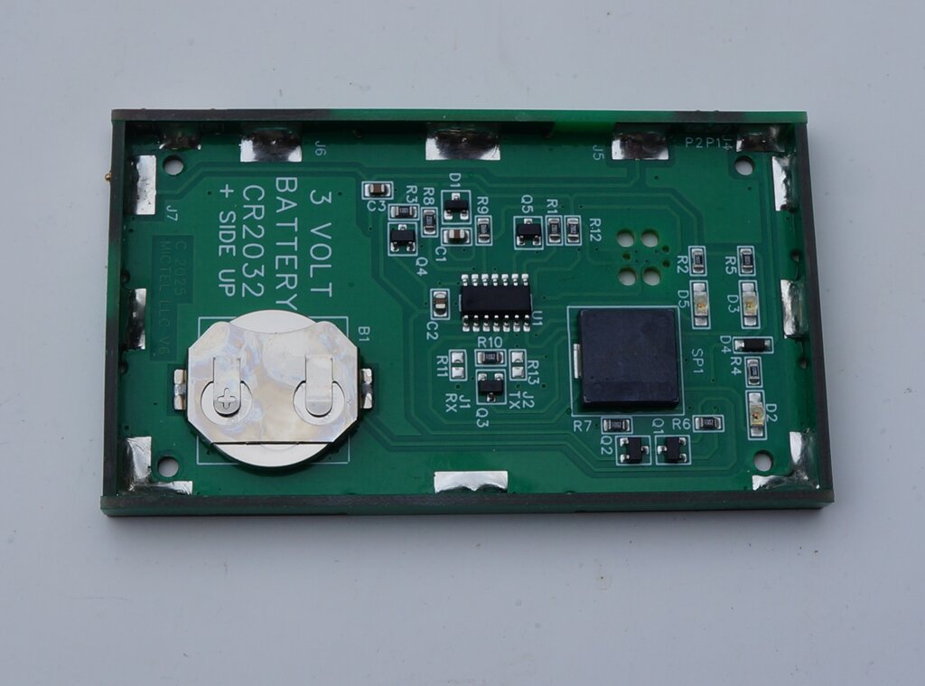
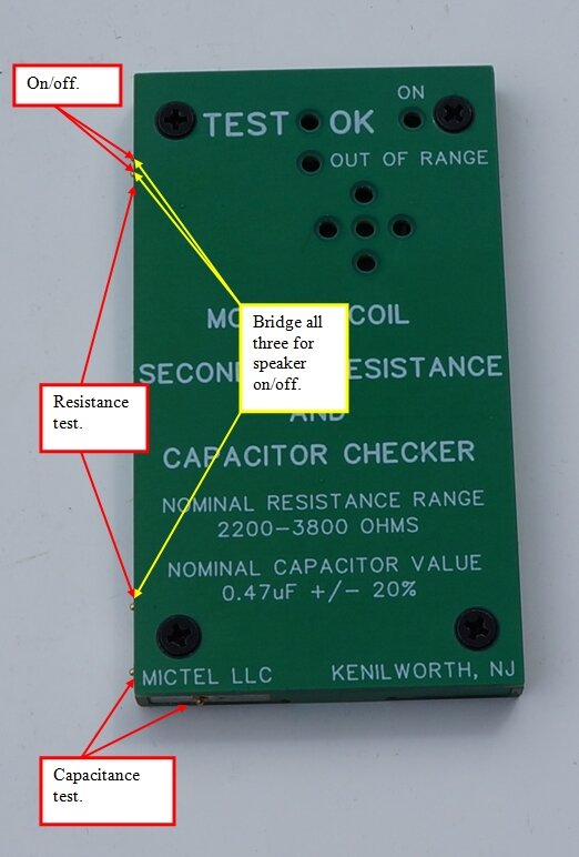
Much more than a simple continuity tester! Note the surface mount
speaker (SP1).
A CR2032 lithium cell powers the tester. Access is by four screws on the front cover. One of the ingenious design features is the screws are threaded directly into the fibreglass printed circuit board. The whole tester is based around a PIC chip, and provides visual indication via red and green LED's. A tiny surface mount speaker also provides audible indication.
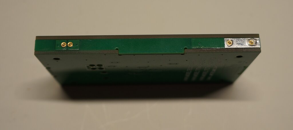
Contacts at left switch the tester on.
Spring loaded gold plated contacts make connection with the coil. A particularly clever feature is that these contacts also do away with any mechanical switches, which would otherwise be required for the on/off and mode functions.
Different modes of operation depend on which contacts are used.
The tester is switched on when the two upper contacts are bridged, as when placed against the coil terminal. It remains powered up for 15 seconds, which then allows for the capacitor test. A red LED indicates power up.
Coil Resistance Test.
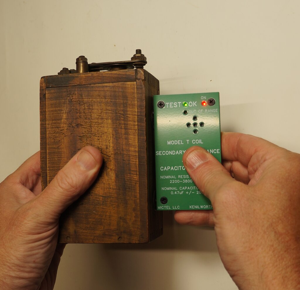
Secondary winding is good.
If the secondary coil resistance is within acceptable range, the green "Test OK" LED lights up and the speaker emits a tone. Testing with a resistance decade box revealed that the green "OK" LED was lit with a resistance between 2.2k and 3.8k. This is exactly the testing range claimed. A continuous high frequency tone (2.5kHz) is emitted when the test is good. The frequency drops to more of a warbling tone (100Hz) when out of range, and another red LED lights up. The speaker is fed with a square wave in both instances. Testing is done with DC; it would appear in a manner similar to a DMM. That is, a constant current is fed into the resistance under test, and the resulting voltage is used to calculate the resistance.
Capacitance Test.
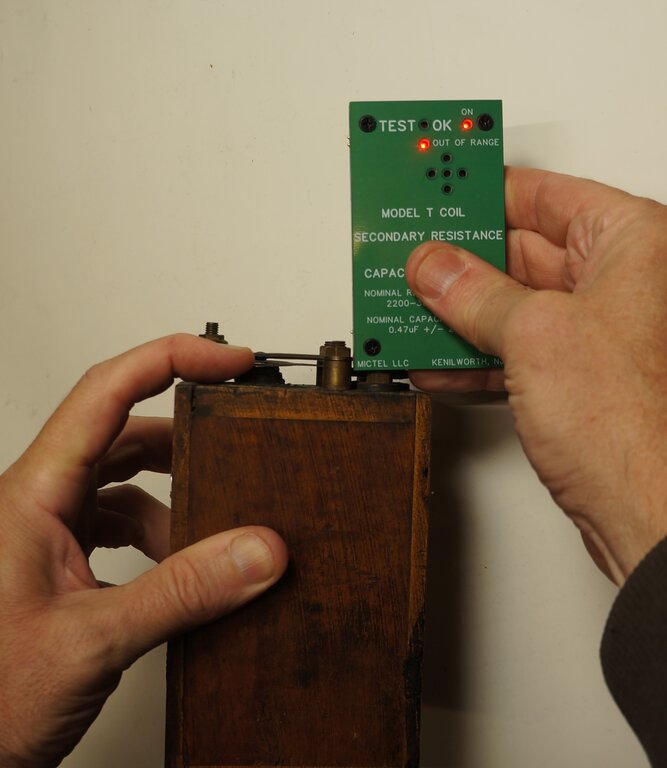
This coil needs the capacitor replaced.
For the capacitance test, the bottom corner of the tester is held against the vibrator points, since the capacitor is internally connected to these. Of course, since the points are normally closed and shorting out the capacitor, they must be held open for this test. Testing with a decade capacitance box again revealed the tester did exactly as claimed. That is, a capacitance range of 0.33uF to 0.58uF showed "OK". The capacitor is tested with what could be described as a low frequency pulse. I measured a 17.5Hz test frequency. The pulse width varies with capacitor value, and presumably it is this which determines the capacitance value.
Incidentally, both the capacitance and resistance tests work in real time. It is not necessary to wait for the tester to reset between each measurement.
Oxidised Coil Hardware.
The capacitance test was the only difficulty
I encountered, and only with some coils. The problem comes down to rusty
nuts and bolts on coils, which have been stored in less than ideal conditions.
It can be very difficult to get a good connection. In fact, with some recalcitrant
coil restorations I've done, I have actually soldered wires to the vibrator
points, to bypass the unreliable nut and bolt connections.
It is important to state that this problem
is not that of the tester, but the coil construction. The
most expensive Fluke multimeter will not do any better. What needs to be
done is to scrape the oxide off the points of contact, when there is difficulty
getting a reading.
Since the capacitor should be replaced
anyway, it is not something I am particularly concerned about.
The resistance test takes place via the brass button contacts on the side of the coil. These may or may not be completely covered in solder, but either way oxidation is not a problem. I had no problem making good contact with even the most decrepit looking coils.
No Beep.
Some sellers might be disconcerted with
a stranger going through their pile of coils, with beeping noises issuing
forth. Where it's desired to silence the buzzer, the tester is held against
a conductive surface, so that connection is made between all three side
terminals. You'll know when you've made connection because the out of range
LED will light. After three seconds, a beep will indicate a change in mode,
and the speaker will now be silent. The same procedure is used to restore
the sound, but this time there will be two beeps.
Battery.
Low battery warning is activated below
2.4V. When this happens, there are a few rapid beeps on first power up,
and the power LED momentarily blinks off at a slow rate during testing.
I attempted measuring the standby battery current, which was about 0.1uA.
This was by extrapolating a reading from a 50uA analog meter. Power up
current was about 7mA, which increased to about 12mA for the capacitance
and resistance tests.
In Summary.
The tester is a handy pocket size unit
which is easily carried to wherever coils might be for sale. Being PIC
chip based, it is completely accurate, and immune to calibration drift.
For the amount of work that would have gone into its design, I think it's
excellent value for what it costs. Restore a few coils for fellow T owners,
and it will pay for itself very quickly.