The Model T Ford Battery
and Charging System.
Part 1 - Know Your
Battery.
The first thing the Model T owner wants
to know when presented with a flat battery is whether it is the battery
or the charging system at fault.
In order to narrow down the cause of the
problem, it helps to first have an understanding of the battery and what
to expect from it.
The lead acid battery.
To use the correct terminology, a battery
is formed by more than one cell being connected together. A lead
acid cell produces 2 volts, regardless of the number, or size, of plates
it has. Thus, to obtain 6 volts, three cells are required, or six for a
12V battery.
In each cell, two sets of lead plates
are immersed in a mixture of sulphuric acid and water, otherwise known
as electrolyte. To charge the cell, external current is connected to
the plates.
Without going into detail of the chemical
reaction that occurs, it is sufficient to say that when the battery is
charged, the acid is stronger than when the battery is discharged.
As the battery is discharged, the plates
become coated with sulphate which comes from the acid. This reduces back
to lead when the battery is charged again.
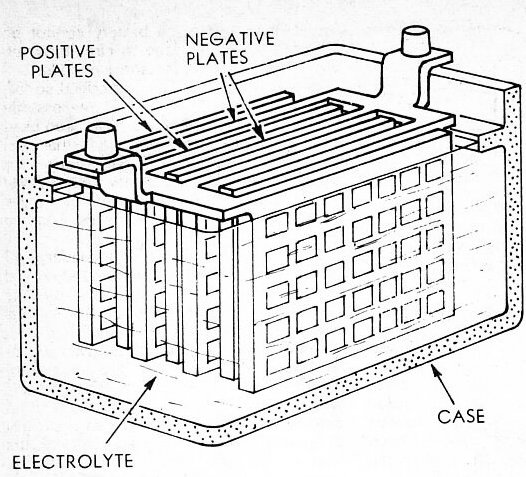
Internal parts of a typical 2 volt lead acid cell.
Because the acid strength is dependent
on the chemical condition of the plates, this can be used to determine
the level of charge. Typically, the specific gravity of the acid is about
1.25 when charged, and 1.11 when discharged. This means the acid has 1.25
and 1.11 times the density of water respectively.
To measure this, a hydrometer is used;
the level at which the internal float sits provides the specific gravity
reading. Hydrometers are becoming obsolete, so far as the average motorist
is concerned, partly because they are messy to use, and partly because
of the increase in maintenance free or otherwise, sealed batteries. With
the high accuracy of low cost volt meters now available, it is more convenient
to measure the battery voltage to ascertain charge level.
The voltage of a lead acid cell is 2.2
-2.3V upon completion of charge. This rapidly falls to around 2.1V and
remains there until the cell has current drawn from it. At 1.8V, the cell
is at a very low charge. These figures are multiplied by three or six,
for 6V and 12V batteries respectively.
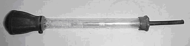
The Hydrometer is an inexpensive
instrument for testing charge level.
Battery capacity.
Every battery has an amp hour capacity,
which is often specified at a 20 hour rate. A typical Model T size 6 volt
battery has about 80 amp hours.
This means that one could draw 4 Amps
for 20 hours before the battery is discharged. The capacity increases for
a lesser current drain, and decreases for greater. This is why it is not
possible to run the starter motor for more than a few minutes, even though
the calculation would suggest 40 minutes cranking time with 150A starter
current. Knowing the battery capacity is useful to determine how long it
can be used for, before being discharged. Pertinent to this are the Model
Ts which have electric lights, or ignition, run from a battery, but no
generator. A common question is, how long can the lights be used for,
before the battery goes flat? First thing is to know the current draw
with lights and ignition on. Assuming this is found to be 10A, and the
car has a 100Ah battery, then 10 hours would be the theoretical maximum.
Because of the 20 hour rate, the time will actually be less, and if the
battery is old or in poor condition it will be less again. Nevertheless,
it gives a rough idea of what to expect. Typical experience suggests about
half the running time to that calculated.
What about Cold Cranking Amps? This
is an indication of the ability to maintain voltage under the high load
of a starter motor. It is expressed in hundreds of amps, and is how much
current the battery can actually provide instantaneously, rather than how
much it can store.
Types of battery.
Lead acid batteries also come in forms
other than the familiar type with removable filler caps, which has been
around for over a century.
So called Maintenance Free batteries
became popular in the early 1980's. These are really just ordinary wet
cell batteries without filler caps. More than the normal amount of electrolyte
is added to the cells, hoping that by the time it has evaporated, the owner
thinks an adequate life has been had from it. Some enterprising motorists
did in fact discover filler caps underneath the moulding in the battery
top with some types, or simply made holes in the tops of others, to inject
water.
In recent years, the Sealed Lead Acid
type has become popular. These go under such brand names as Optima or
Orbital. The generic name of Gel Cell is often used for the smaller
non automotive types. The operating principles are the same as the wet
cells, but the electrolyte is in paste form. This means the battery can
be used in any position without spillage. Small SLA batteries are popular
with owners of non electric Ts for ignition coils and low powered lighting,
because they can be stored unobtrusively under the seat without acid fumes
and spills.
However, the cells are not intentionally
vented to the atmosphere. This means hydrogen production must be kept at
a minimum. Because of this, charging requirements are far more stringent,
and normal car battery chargers are not suitable for the smaller batteries
due to the likely risk of overcharge.
For the Model T owner, the "Red Top" Optima
is highly recommended. It uses a spiral wound plate assembly. While it
is much more expensive than a conventional wet lead acid battery, the lack
of acid migration over the battery terminals and surrounding metal work
is welcome, as is never having to maintain it. Importantly, life is longer
than a conventional battery, but also the internal resistance is lower
which provides for better starting. It should however be used with a voltage
regulator, and these are discussed further on.

Optima sealed lead acid battery.
Discharging.
Allowing a lead acid battery to get below
about 1.8V per cell will cause irreparable damage. When this happens, excess
sulphate builds up on the lead plates, insulating them from the electrolyte.
A classic scenario is the flat battery because the lights were left on
all day. Just one bout of this causes irreversible plate sulphation. Even
though a charge the next day may make it appear that all is well again,
the capacity is likely to be reduced. The battery will now no longer have
its full life expectancy and soon the owner may find the need to occasionally
use a mains powered battery charger, when previously the cars own charging
system was sufficient.
Self discharge causes just as much damage.
All batteries discharge by themselves, even if not connected to anything.
Many a Model T has suffered the death of a battery from self discharge
through lack of use. Unfortunately, merely charging the battery the night
before a drive, after the car has sat for a few months, will not reverse
the deterioration. Fortunately, it is possible to keep the battery fully
charged at all times, and this will be explained further on.
Note also, there are instances of a faulty
electrical system being responsible for a high rate of discharge, leading
one to think the battery is faulty. Particularly prone to this are cars
with modified charging systems, which with incorrect wiring may well charge
the battery, but still draw current when everything is turned off. A very
simple test for the possibility of this fault is to connect an automotive
test lamp between one of the battery terminals and associated battery post.
With everything switched off, any leakage will be indicated by the test
lamp. Those proficient with multimeters can do the test with more accuracy,
but starting on the 10 amp DC range and reducing the range as necessary.
Unfortunately, the Model T dashboard ammeter
is not sensitive enough to show low levels of leakage.
Part 2 - Battery Charging
and Maintenance.
Correct charging.
It may be a surprise to know that a good
quality lead acid battery can last 10 or more years if it has always been
correctly charged and maintained from new, and never allowed to discharge.
Lead acid batteries are the simplest of
all types to charge.
The ideal method is to apply current to
the battery until each cell has come up to 2.4V (i.e. 7.2V for a 6V battery),
or the specific gravity is 1.25. Then the voltage is dropped to maintain
the charge at 2.3V per cell. Failing to stop charging at the higher voltage
will cause excess gassing and loss of electrolyte. This is most important
to avoid for sealed batteries. Unfortunately, the standard Model T charging
system is very much of a compromise, and does not terminate charging at
all. This will be examined later to see how the undesirable effects can
be minimised.
Note that the specific charge voltages
can differ slightly for different batteries, but this is usually available
from the manufacturer's specifications.
In practice, conventional wet lead acid
batteries are forgiving enough to tolerate some overcharge, which invariably
occurs with simple charging systems.
Charge Current.
What current is the best to charge at?
Over the last century of battery technology, it has been found that a good
rule of thumb is about a tenth of the battery capacity. So, its no coincidence
that the typical low cost car battery charger is rated at 4-6A, for the
common 50Ah 12V type of battery. Those with 6V batteries can usually charge
at around 8-10A. If youve followed everything so far, you can probably
guess that the time taken to charge a totally flat battery at this rate
will be 10 hours. In practice, because the battery is not 100% efficient,
up to14 hours are recommended.
A battery can be charged much more rapidly
with higher current, but this should only be done in an emergency, as the
high current can buckle the plates, overheat the electrolyte, and cause
excess gassing. The charging must be terminated immediately the charge
is sufficient. Even so, this kind of treatment is detrimental to its life.
Of course, a battery can be charged at
a lower rate, but will simply take longer.
It is important to note that the gas vented
from a charging battery is hydrogen, and that explosions have occurred.
Usually, this is when battery chargers or other items are connected or
disconnected from a furiously bubbling battery. The spark produced ignites
the hydrogen surrounding the battery. This is why the instructions for
jumper leads often state to make the negative connection to somewhere on
the chassis away from the battery. Chargers should be turned off at the
mains before connecting or disconnecting from the battery.
Types of Chargers.
In practice what does all this mean for
the Model T owner who needs to charge the battery from the mains? The basic
low cost battery charger works well enough here. This is the kind of charger
that puts out about 4A and includes a simple ammeter. The circuitry of
such a charger is essentially just a transformer and rectifier. It does
not contain any voltage regulation. With it one also needs a hydrometer
and/or digital volt meter to check the charge this can be done every
few hours or so. The key point is to not leave the charger on for more
than necessary. A time switch is a good idea if the charger has to be left
unattended.
In the modern day, so called "Intelligent"
chargers have become available, which can be connected indefinitely. These
provide the ideal charging conditions, in that the battery voltage is taken
up to 2.4V per cell, and then dropped to 2.3V, at which the battery is
maintained but not overcharged.
Some simple chargers have a LED bar graph
voltmeter to show the charge level. Beware that these types do not shut
off when full charge is shown, unless the specifications say otherwise.
While the Optima kind of sealed car
battery is rugged enough to be charged with conventional chargers (although
not recommended for long term use), the smaller Gel Cell types are not.
The high current will damage the internals and the electrolyte will dry
out. Special chargers are available which should be used.
Battery Maintainers.
Becoming popular among vintage car owners,
these solve the problem of battery self discharge, when the car is not
used for long periods. The maintainer is connected to the battery whenever
the car is garaged, and keeps it at 6.9 or 13.8V. Thus, the battery does
not discharge, and because the voltage is fixed, it cannot overcharge.
The ideal state of equilibrium is reached, eliminating the need to constantly
check water level or charge state. The battery is always ready for use
at full charge. Unlike chargers, maintainers are a precision unit, and
provide only enough current to offset self discharge. To charge a flat
battery from one would take several days, if not longer. The Model T owner
should therefore keep a conventional charger, as well as a maintainer.
As previously described, many "Intelligent" chargers do combine charging
and maintaining, and are a more convenient option.
Charging a 6V battery from a 12V
charger.
While 6V battery chargers are available,
it is possible to charge a 6V battery from a 12V charger. All that is required
is one or two headlamp bulbs. These serve to limit the charge current,
and absorb the extra 6V. Start by connecting the 12V battery charger to
the 6V battery with one bulb in series with one of the connections. The
bulb will light to show charging is taking place. If more charging current
is required, connect an extra bulb across the first. It does not matter
if a 6 or 12V bulb is used because the difference in voltage between the
charger and battery will be around 6V.
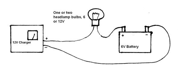
It is quite practical
to use a 12V charger with a 6V battery as shown above.
The basic kind of charger is necessary
here, as types that monitor the voltage will be confused. It is not possible
to use a 12V maintainer or intelligent charger with a 6V battery this way.
Pills and Potions.
Since cars were first fitted with lead
acid batteries, all sorts of additives have been made available to the
gullible motorist, in order to rescue an unusable battery. Generally, these
are intended to break down the excess sulphate. In recent years electronic
devices have become available which pulse a high voltage through the battery
to do the same thing. Results appear to be quite variable, and it can take
quite some time to achieve the desired effect. Whether or not these methods
are successful, it is highly doubtful that full performance can ever be
restored.
Testing a battery.
Usually, a battery only gets tested when
something is amiss the battery has been charged but the lights are still
dim, etc. The first thing to do is check the electrolyte. At least 50%
of problems are because of electrolyte being below the tops of the plates.
Distilled water should be used to top up.
The next thing to do with an apparently
faulty battery is charge it off a mains powered charger, so as to eliminate
the possibility of a faulty electrical system in the car. If the ammeter
on the charger is showing very low current, this is indicative of one or
more faulty cells. One can wait a few hours to see if charge current increases,
but it is likely the battery is ruined. Sometimes, it is noticed that by
touching the side of the battery, that one cell is warmer than the others
this is also a sign of failure.
At the end of the charge period, each
cell should be checked with the hydrometer. A cell with low specific gravity
while all the others are high also indicates problems.
The simplest test is then to run the battery
into a load after a full charge. For this, the cars headlights are ideal.
Measure the voltage at the actual battery posts, with the lights on. Do
not measure the voltage anywhere else, as wiring resistance will give a
false reading. If it drops below 6 or 12V the battery is faulty.
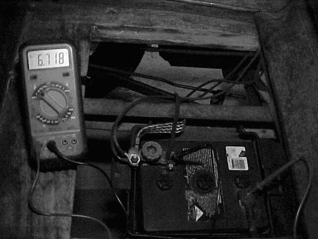
Taken off the maintainer before this reading was taken, 6.7V shows
the battery to be in good condition.
With a faulty battery, the voltage often
drops in multiples of two; each loss of two volts indicating a defective
cell.
Part 3 The Ford Generator.
With commercial pressure forcing Ford to
eventually adopt the electric starter, a lead acid battery had to be included,
as the current drawn by a starter motor is too high for any kind of dry
battery.
A means of recharging the battery was required, so a generator driven by
the car engine was the obvious solution.
Generator Principles.
 .
.
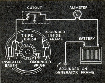
Essential parts of a charging
system using a 3rd brush generator.
As is well known, a generator works on
the principle of an electrical conductor (the armature windings) rotating
in a magnetic field (developed by the field coils fixed to the generator
body). The strength of this magnetic field, in turn, controls the generator
output current. Thus, by controlling the current through the field coils,
the charge rate can be set to a particular current.
This is the purpose of the third brush.
Without going into the complexities of what really happens, it is sufficient
to know that by sliding the 3rd brush towards the insulated brush, field
coil current increases, and therefore the battery charge rate. A simple
way of explaining this is to think of the voltage gradient across the armature,
starting at the grounded brush (0 volts), and going towards the insulated
brush (6 volts). By connecting to the armature at an intermediate point
via the 3rd brush, it can be seen how the current fed into the field coil
can be varied.
No Voltage Regulation.
The generator fitted to Fords between
1919 and 1938 is of the 3rd brush type.
This kind was chosen because it fits in
with the simple but practical theme. It does not require an external
current regulator, as do two-brush type generators. Over a wide range of
driving speed, the charge remains reasonably constant. However, there is
no voltage regulation. What this means is that once the battery has reached
full charge, (about 7 volts), it continues to be charged at the full rate,
which shortens battery life.
The concept of voltage regulation was
well known at the time, and in fact many other cars of the T era did use
it. A voltage regulator works by reducing field coil current when the battery
reaches full charge. However, Ford, and others more interested in economy,
decided they could ignore it.
The idea was simply to set the charge
current to the lowest point before a flat battery is likely. The problem
now is that when high currents are drawn (e.g. headlights), the battery
wont fully recharge. Alternatively, if the charge current is set high
enough to allow the headlights to be used, without discharging the battery,
the battery will be overcharged when the headlights are not used.
A compromise has to be reached in this
situation, but the 10 to 12 amps as recommend in the Ford Service Manual,
is too high for driving conditions in the modern day.
Charge Current.
What should one set the charge current
to? Firstly, the generator maximum power is 100 watts. This translates
to 16A for 6V, or 8A for 12V, before excessive wear or burn out results.
Fords idea of setting charge current
is based on being able to run the headlights continuously without having
a flat battery. However, it is enough to damage a fully charged battery
on a long drive when the headlights are not used which is typical of
Model T driving today. As the standard electrical system draws little current,
the charge rate does not need to be very high at all. What of the huge
current drawn by the electric starter? While it may be around 150 amps,
remember it is for a very short period. To explain this, consider one minute
of electric cranking. Drawing 150A for one minute is the same as drawing
2.5A (equivalent to one brake lamp) for one hour. Put in perspective like
this, it is clear the overall energy consumption is actually very low.
It is for this reason one hears of non
generator cars being able to tour for a week on one battery charge.
Over a long period of time, I have found
5A to be the ideal charge current for a 6 volt system. This accommodates
occasional use of the headlights and starter, as well as the ignition coils
full time. 5A is not so high as to cause excess electrolyte loss. Typically,
the battery might need topping up once or twice a year. My first Model
T battery provided ten years of service, and never went flat.
For those with 12V systems, the charge
rate should be roughly halved; about 3A.
Running on no load.
As the armature spins and produces current,
the field coils become more energised, causing the armature to output more
current, which energises the field coils even more. Its obvious that a
runaway condition exists, and the generator will soon burn out, unless
the output voltage is limited. As there is no voltage regulator, the only
thing to do this is the loading by the battery. If for any reason, the
battery becomes disconnected whilst the engine is running at speed, there
is a real risk of a burnt out generator. This is especially so where the
generator has been set to a high charge current. Setting it to a low current
like 5A will provide some protection if this situation occurs.
Not only that, any accessories in use
will be damaged from excessive voltage. Such a scenario does happen, and
is often the result of a faulty cut-out, battery isolation switch, loose
terminals, or even a faulty battery. This is the likely fault if light
bulbs start mysteriously burning out at a rapid rate.
There is also the situation where some
T owners wish to run an unconnected generator, because there is no battery
or charging system in the car.
The generator terminal must be earthed when running into no load.
The cut out need not be present.
This can be done quite safely simply by
earthing the generator terminal. Some may wonder, Wont shorting out the
generator overload it? The answer is no, because the armature is prevented
from creating any voltage, which then prevents the field coils producing
a magnetic field.
Typical Generator Faults.
Apart from the usual faults that occur
with any brush type motor or generator, such as worn bearings, worn brushes
or scored commutators, there are some common faults pertinent to the Model
T generator:
Unless the generator has been reconditioned
with a new brush plate installed, any attempt to adjust the 3rd brush is
likely to destroy an original brush plate. The original material used for
this tends to crumble where the brush is tightened. The result is a short
circuit to ground, and is one of the most common causes of no generator
output. There is an excellent fibreglass reproduction which overcomes this
problem.
Despite years of being soaked in oil,
the windings appear to be quite reliable, except where charge current has
been excessive. Crumbling insulation and charred windings means a trip
to a rewinder, and if one has ideas of using 12V, the generator should
be rewound to suit.
When removing the back of the generator,
note exactly where the field coil wires connect to the brush plate, before
any further disassembly. Note the crossover of wires. If these should be
connected in reverse, the generator can be set up in the normal way, but
causes a rather high discharge current when an attempt is made to set the
third brush in the car with the engine running. The reason is that this
reverses the direction of rotation.
Flashing the Generator.
If a generator is in good condition but
fails to produce an output, it may need to be flashed. Going back to
the principles of operation, it may be wondered, how can the armature produce
output to energise the field coils which are needed to make the armature
produce output in the first place?
The answer is that there is a small amount
of residual magnetism, in the iron core of the field winding. It is not
much, but enough to start the process.
Where does this residual magnetism come
from? When the generator is manufactured, it is flashed.
If a generator has lost its residual magnetism, flashing will restore
it.
For the Model T, the simplest way to do
this is simply bridge the cut out terminals for a second or two. This feeds
battery current into the generator windings and remagnetises the core.
Flashing is also required if a generator from a positive earth system is
to be changed to negative earth.
The residual magnetism may be lost if
the generator has not been used for many years. If flashing is regularly
required, it would indicate commutator or winding problems the losses
being too high to allow the residual magnetism to start the process.
Setting up the Generator.
After all the details given so far, actual
setting of the generator is very easy.
If the generator has been dismantled or
worked on, it is necessary to first set the brush plate. First the generator
is removed from the car. The third brush is then lifted from its holder
so as not to make contact. Then, the four brush plate screws are loosened
just enough so the brush plate can be rotated. Now, with a set of jumper
leads, connect a 6 or 12V battery. The generator will now run as a motor
(incidentally, a quick go/no go test). Move the brush plate in one direction,
then the other. At a certain point, the motoring stops and then reverses
direction. Its at this point where it doesnt move, that the brush plate
needs to be tightened. Now return the 3rd brush to its original position,
and again the generator will run as a motor.
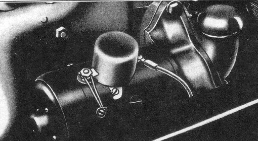
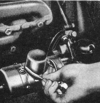
Reinstall in the car, start the engine,
and run at a fast idle. The third brush can now be adjusted by loosening
it and sliding it across the brush plate until the desired current is obtained.
Retighten without crushing the brush plate, and adjustment is done. No
further adjustment of the brush plate is required, even if the current
is readjusted, unless internal work is done to the generator.
Part 4 The Model
T Cut-Out
Often a source of confusion, cut outs and
regulators are two different things. As described previously, the standard
Model T incorporates a cut-out only.
What is its purpose, and why is it necessary?
The Cut-Out Function.
If the generator were to be connected
directly to the battery, it would certainly provide a charge in the normal
way, so long as the engine was rotating, at or above a fast idle. However,
when the engine slows down or stops, the battery current would now flow
back into the generator, and try to run it as a motor. This is obviously
undesirable, because not only will the battery discharge, but the generator
will sit in a stalled condition, and its windings will soon overheat.
The immediate solution to this is to have
a switch to connect the generator to the battery when it runs above a certain
speed, and disconnects it when it slows down. A simple switch operated
by the driver, could indeed perform this function. However, the possibility
of not remembering to use the switch at the right time makes this idea
impractical. The switch needs to be automatic.
How it works.
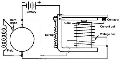
The cut-out is rather similar to a horn
relay in internal appearance and operation. One difference is that there
are two windings on the core instead of one. When current is passed through
windings around the core, a magnetic field is developed which attracts
the contacts together, completing the battery to generator circuit.
Expanding on this, we will just examine
the voltage coil first. Note that it connects directly across the generator
output. Now imagine what happens as the generator is brought up to speed.
The magnetic field starts to build up in the core, and when strong enough,
the contacts close.
At this point it can be seen that current
can now flow to the battery, via the contacts and the current coil.
The current coil is only a few turns of
heavy gauge wire, so it has no effect on the charge current. It does, however,
develop a magnetic field of its own. This adds to that already developed
by the voltage coil, and the contacts remain closed. The battery thus starts
charging.
So far, we have accomplished the task
of automatically turning the switch on.
Operation becomes slightly more complicated
when the generator slows down and we want the battery to disconnect again.
What happens now?
Keep in mind that the contacts are still
closed, meaning the battery is connected to the generator. But this also
means the battery is connected to the voltage coil, which will keep the
contacts closed, and now the battery will discharge through the generator
and voltage coil.
Indeed it would, except this is where
the current coil comes into play. Consider that when the generator stops,
the current now flows from the battery into the generator. The current
has reversed direction, therefore reversing the magnetic field around the
core. Being in the opposite direction, it cancels out the voltage coil
field, and now the contacts open. The battery is now isolated from the
generator and cannot discharge.
Cut-Out Adjustment.
The only adjustment is the voltage at
which the contacts close. If it is too low, the battery will discharge
through the generator when its output is too low to provide a charge.
If it is too high, the battery will not
start charging except when engine speed is higher than normal.
The cut out is thus set to close when
the generator voltage has reached the level just above that of a fully
charged battery; i.e. about 7.5V.
The adjustment is most easily done using
a variable power supply connected across the voltage coil, and setting
the contact tension so the contacts close just as the supply reaches 7.5V.
Failing the availability of a variable power supply, the generator itself
can be used. An analogue voltmeter connected across the generator
output can be used to measure closing voltage.
Cut -Out Faults.
The construction methods used for the
original cut-out means that those using them really need to do a rebuild.
Remember, a cut-out that does not close can result in a burnt out generator.
The problem is the internal electrical
connections rely on rivets, which loosen over time. Additionally, the insulating
material used crumbles away, making a short circuit possible.
A piece of blank fibreglass printed circuit
board is ideal for replacing the insulators, but any similar high temperature
insulating material can be used.
All riveted connections need to have short
lengths of wire soldered across them.

Inside a reproduction Ford cut out. Failure of any of the internal
parts, or connections thereto, can result in a damaged generator.
Sticking contacts are likely to show signs
of pitting, so by means of a file these can be repaired. Sticking points
will show up as a discharge reading on the ammeter with everything in the
car switched off.
Diode Cut-Out.
In view of potential problems with mechanical
cut-outs, some owners replace the internals with a diode. A diode will
easily fit in space formerly occupied by the relay, but it will need proper
cooling. With a charge current of 5A, heat dissipation will be around 5
watts with a silicon diode, so some kind of heatsink is required. A Schottky
diode has a lower voltage drop and will thus dissipate less heat.
The type of diode is not critical, except
it should have a high current rating. For reliability, something in the
region of 25A or more should be used. Diodes extracted from modern car
alternators are a popular and effective substitution, although Schottky
diodes will run cooler, and not need as much heatsinking. A disadvantage
of solid state diodes is that if they fail, they usually do so in the form
of a short circuit. If this happens, the symptoms are the same as stuck
points with a mechanical cut-out.
Ground Switch.
An idea made popular by an old Tinkering
Tips article, was to install a switch to earth the generator terminal,
when charging wasnt required. A supposed beneficial side effect was that,
with the generator not providing any power, a certain amount of horsepower
would be saved. However, we must realise that with many such articles,
tinkering was an apt description, and were without any scientific or
methodical basis. At a speed of 60km/h and a charge current of 6A, the
power consumed by the generator is only 0.18hp. To put things in perspective,
one horsepower is 746W, which equates to over 100A charge current! For
those that still want to try the idea, note that it must only be used with
diode type cut-outs. This is because when in operation, a mechanical cut
out provides a direct connection to the battery. Grounding the generator
when the cut-out contacts are closed will result in a destructively high
current flow before they open. If one could be absolutely certain the grounding
position was only selected with the engine at idle speed, or switched off,
one could get away with the scheme with mechanical cut-outs. But, human
nature being what it is, would eventually mean the switch was operated
at the wrong time.
Voltage Regulators.
As explained previously, the cut out has
no regulation feature. That is, it does not terminate the charging when
the battery is full. While the technology to deal with this was available
at the time, Ford chose not to use it until the late 1930s. Some T owners
therefore, have adapted regulators from other cars to use with the Model
T generator. This is quite in order, but it does require that the field
winding be brought out to a separate terminal on the generator. However,
given the appearance of Model T specific regulators in recent years, such
a modification is scarcely worthwhile.
Fun Projects Voltage Regulator.
This modern accessory is recommended for
those who wish to overcome the limitations of the stock charging system.
It means one can charge at 10A (at 6V) without overcharging the battery.
Essentially, it contains a diode cut-out, and also an electronic grounding
switch, which cuts off the generator output when the battery is charged.
Generator wear is less, because its operating only for a short period,
rather than continuously. It eliminates problems with mechanical cut-outs,
and most importantly, eliminates battery overcharge. In effect, a modern
charging system is gained with no modifications to appearance or wiring.
The unit is simply a drop in replacement for the original cut out.
However, Fun Projects has ceased to exist,
and the regulator is no longer manufactured. The whole story of the Fun
Projects regulator is explained here https://www.cool386.com/regulator/regulator.html
A New Voltage Regulator.
In view of the advantages of voltage regulation,
and that there was a constant demand for regulators, I was involved in
the design of a replacement, which is now being manufactured by another
MTFCA member. This is described here https://www.cool386.com/ford_regulator/ford_regulator.html
Home