The first pentode super-regen receiver to be described on this site.
The first pentode super-regen receiver to be described on this site.
Continuing with the series of super-regenerative receivers using different valves, the latest version uses the 6AM6 pentode. It's the first design to be presented here using a pentode; all valve versions so far have used triodes. Apart from having a large quantity of 6AM6's in my collection, it was felt that a greater audio output should be available by using a pentode. Unfortunately, as will become evident later, this was not acheived.
Introducing the 6AM6/EF91.
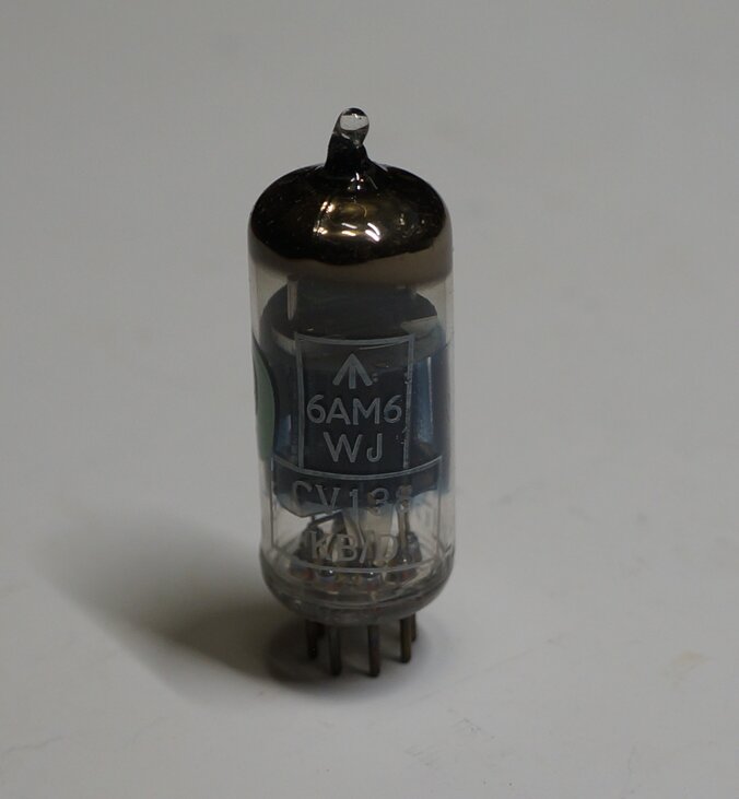
The 6AM6 is a pentode intended for operating
up to VHF. It was released post-war, and was a very popular valve in the
UK. It is also commonly known as the EF91 in the European numbering system,
and the services type number CV138 and CV4014.
I suggest reading this
well written article to learn more about the 6AM6 and its multitude
of type numbers.
In terms of consumer equipment, the 6AM6
found itself used mostly in TV receivers and FM receivers during the 1950's
in the UK. In Australia, it was used as a video IF amplifier in at least
one TV, made by Healing. Most of the examples of this valve found in Australia,
however, appear to have come from British made military equipment sold
on the disposals market. I cannot recall any U.S. designed equipment using
this valve.
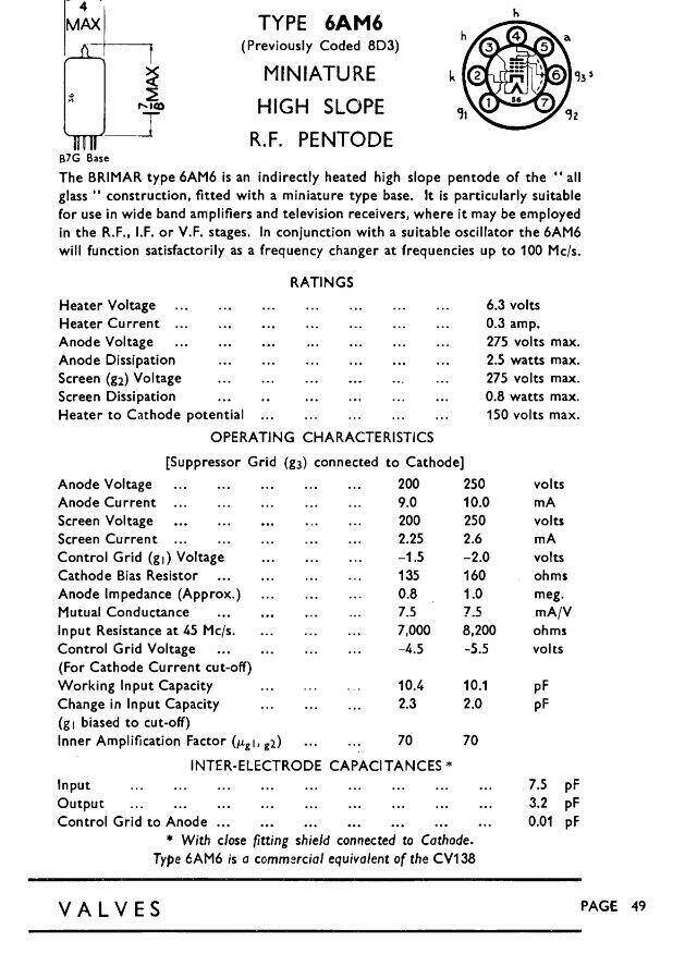
From the STC Brimar data.
Using the 6AM6 as a Super-Regenerative
Receiver.
While the 6AM6 could have simply been
wired as a triode, and used as per the other circuits so far described,
it felt that was a bit wasteful. A pentode connection would make full use
of the valve, and provide greater audio output.
A characteristic of pentodes is that the
cathode current remains much the same, despite a variation in plate current,
provided the screen voltage is fixed. In fact, this property is sometimes
used to create a constant current source.
For the triode circuits, the higher the
plate resistor, the higher the audio output. However, a problem occurs
in that as the plate resistor is increased, the cathode current drops off,
and we get to a point where oscillation becomes weak and unreliable.
If we use a pentode instead, the screen
grid can be fixed at a certain voltage and this determines the cathode
current. The plate resistor can be made higher without affecting oscillation.
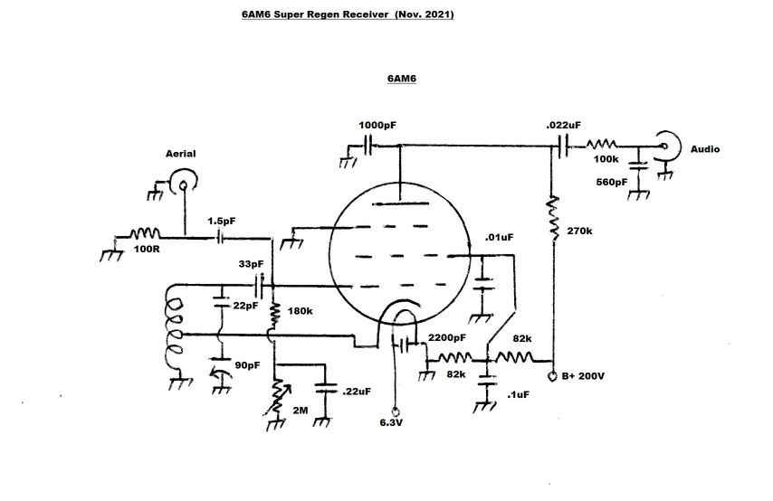
Circuit of the basic 6AM6/EF91 Super-Regenerative Receiver. Reducing
the plate load to 150k will provide better audio frequency response.
As can be seen, the circuit follows the
format of the previous triode receivers, except that there is now a screen
and suppressor grid. Note that the plate resistor is now 270k instead of
the previous 56k or 150k. Initial thoughts were that increasing the plate
load would increase the output.
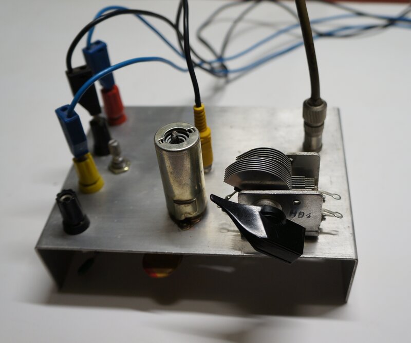
The circuit was built up on the test panel,
and operating conditions optimised.
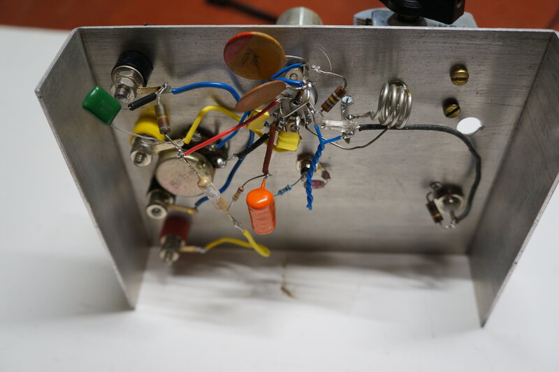
6AM6 circuit built on test panel.
Connected as a pentode, the screen grid
(g2) effectively functions as the plate of the oscillator. Together, with
the control grid (g1) and the cathode, we have a typical Hartley oscillator
with cathode feedback.
The oscillator is self biassed with the
grid leak components; the 33pF grid capacitor and 180k grid resistor. The
value of these components also forms a time constant, long enough such
that the oscillator will go in and out of oscillation at a supersonic rate.
This is a standard method of achieving
self-quenching.
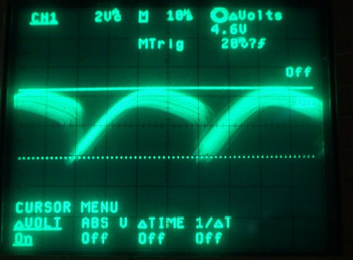
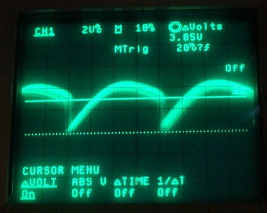
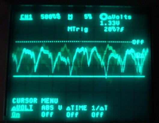
Plate waveforms showing the peak to peak voltage, and the negative
going amplitude. These should be adhered to for best operation.
Grid Voltage Control.
Some control over the overall grid voltage
is necessary to optimise the level of oscillation and quench frequency,
so that the receiver operates at maximum sensitivity. The 180k grid resistor
can be taken to a variable negative voltage supply to adjust this, or the
negative grid voltage developed from the oscillation can itself be used.
This was first tried with the 6GK5
circuit and due to its simplicity and degree of self regulation, has
also been used in this circuit. If the DC resistance of the grid circuit
is increased, a sufficiently high voltage will be developed that will cut
the valve off and prevent it oscillating.
Thus, by making the DC circuit resistance
variable, the grid voltage can be adjusted over a wide enough range. The
.22uF capacitor prevents the quench circuit seeing the added resistance,
and so the grid still sees 180k of AC resistance, regardless of the setting
of the 2M pot. The circuit works best with around -1.8V across the .22uF
capacitor.
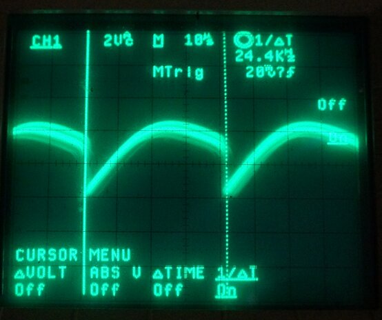
Quench frequency is 24.4KHz.
Up to this point, the circuit oscillates
and self quenches exactly the same as the triode designs.
Now to extract the audio - a much higher
value of plate resistor can now be used since it is no longer determining
cathode current. In practice, there is a limit to what this can be, because
of the loading of the following stage. It is pointless to increase the
plate resistor to a value higher than the following grid resistor, since
there will be less than maximum power transfer. Also, if the resistance
is made excessively high, stray capacitance starts to roll off the upper
frequency response.
In this circuit, I used 270k which is
a typical value for a resistance coupled audio amplifier.
Typical audio output level into a 500k load.
As usual, there is a simple low pass filter to reduce the quench signal, using a 100k and 560pF on the audio output. With the higher plate load, the 560pF has more of a roll-off effect than it does in the circuits where the plate resistor was 150k. The 560pF can be reduced, provided the quench frequency does not overload the subsequent stages.
As for the screen grid voltage, experimentation soon found that 100V provided the best sensitivity and output with lowest noise. Two 82k resistors form a voltage divider to provide the 100V. These resistors are not critical, and a 100k pot was used at first (effectively two 50k resistors).
The suppressor grid connection is common to an internal screen, and so this connection was earthed, rather than taking it to the cathode, since this is live at RF.
Construction.
This has been covered elsewhere on the
site, but the usual rules apply for VHF circuitry - a ground plane, short
leads, and good bypassing.
The aerial coil is four turns of 1.6mm
tinned copper wire, 10mm diameter. A 10mm drill bit is a convenient
winding former. The width of the coil is about 10mm, and by spreading or
contracting the width, some adjustment of frequency range is obtained.
The cathode tapping is at two turns.
Ideally, the tuning capacitor should be
15pF for complete coverage of the 88-108MHz FM band. It should be an air
spaced type for best performance. Since the availability of variable capacitors
is limited in the modern day, it may be necessary to use a higher value
with a padding capacitor. This is what I have done with many of my super-regenerative
circuits. In this circuit I have used a 22pF capacitor in series with a
90pF variable air spaced tuning capacitor. The higher the value of tuning
capacitor, the more non linear is the tuning. That is to say, the higher
frequency stations are cramped together with the lower frequency stations
spread out.
The grid and padder capacitors can be ceramic
or polystyrene. The 1.5pF aerial coupling is made of insulated plastic
wire twisted together to form a gimmick capacitor. Length is 3cm.
For plate and heater bypassing, I used
MKT capacitors, although officially ceramics should be used.
The screen grid is bypassed with a .01uF
ceramic, for RF, and also with a polyester .1uF for the quench and audio
component. If a .1uF ceramic is available, it can be used on its own.
The regeneration control .22uF bypass
is a ceramic, but MKT or polyester should also work.
Voltage ratings are not important except
for the 1000pF plate bypass and the .022uF audio coupling capacitor. Both
these should be rated at the highest B+ voltage that exists before the
receiver warms up. The screen grid bypass needs to be 100V rated; higher
if the no load B+ is higher than 200V.
Resistors can be all 1/2W types, although
1/4W can be used for the 180k, and 100k.
Although a shield is pictured for the
6AM6, this is not actually necessary, since this valve already is already
internally shielded.
Heater Bypassing.
One side of the heater is earthed, and
the live side is bypassed to earth with a 2200pF capacitor which can be
MKT or ceramic. This is important since the cathode is live at RF, and
has some capacitance to the heater. If the heater is not bypassed, oscillation
might be weak or erratic.
There is some 50Hz ripple evident in the
audio output on the CRO, although it is not actually audible. If this is
problematic with particular circuits or 6AM6's, feeding the heater from
DC will eliminate it. See below:
**Update Re
50Hz Hum**
It appears that the use of a cathode tapping
on the oscillator (aerial) coil instead of an RFC is the cause of mains
hum being present in the audio output. None of the circuits using an RF
choke in the cathode circuit have exhibited this problem.
The mechanism by which this occurs is
probably a form of modulation hum, where 50Hz from the heater is coupled
by the heater to cathode capacitance, directly into the tuned circuit.
If you wish to use the cathode tapping
method, and the hum is not a problem, there is no reason not to do so.
Otherwise, the valve must be heated with DC, or the original cathode RF
choke circuit used.
**Update Re
Grid Voltage Control**
The method of using
the grid leak voltage as the actual regeneration control voltage works
well, and simplifies the circuit. However, it does not provide complete
cut-off. For 'normal' reception this is not important, and indeed, the
self regulating feature is convenient, and appreciated by less technical
users. Where utmost sensitivity is required, the adjustment range needs
to be able to take the detector just out of oscillation. Therefore, for
any kind of 'quality' or 'DX' type of receiver, the grid resistor should
be taken to a variable negative voltage supply instead.
Voltages.
With 200V B+ and typical receiving conditions,
the plate voltage is 135V, screen is 100V, and grid at the regeneration
control is -1.75V. The screen grid voltage can be stabilised with any typical
regulator circuit if supply voltage variations are problematic. The most
noticeable effect of this is drift in frequency. Similarly, regulating
the heater supply can also further improve stability.
Performance.
Surprisingly, with an FM test signal of
100uV at 103.7MHz, modulated with 1kHz at 40kHz deviation, audio output
was only 350mVp-p (124Vrms).
This is a lot lower than the 6BL8
receiver with its 620mVp-p output.
It was then found that the theory of using
a pentode connection made very little difference. Changing between 150k
and 270k plate resistors actually made no useful difference in audio output
level. Anyone building this receiver should use 150k for the plate load,
since there is less high frequency roll-off due to the quench filter. Finally,
the 6AM6 was tested as a triode. This too, made little difference, except
that the audio level was slightly lower again.
FM reception starts to become noise free
around 40uV, with AM slightly better. Signals under 10uV can be heard,
but are quite noisy.
Without any modification, the circuit
was tried as a regenerative receiver simply by reducing the B+ to around
50V. Of course the sensitivity is a lot less, though adequate for strong
stations. Tuning is more critical because of the reduced bandwidth, but
the freedom from noise and improved sound quality does make this method
of reception worth investigating further for a local station receiver.
In conclusion, it's a good receiver if you are looking to use a 6AM6. However, use it pentode connected and with a 150k plate resistor. The following audio amplifier will need a sensitivity of about 120mV rms.