
Controls from left to right are On/Off, Regeneration, Quench Frequency, and Volume.
Controls from left to right are On/Off, Regeneration, Quench Frequency,
and Volume.
With the exception of the 7193 receiver, all the valve super-regenerative receivers described so far have used miniature valves. For some time, I had contemplated the construction of a WW2 style 'all bakelite base' valve VHF receiver. The key to its practicality was the super-regenerative detector. Beyond that, the audio and rectifier circuits are easy with ancient valves. With the success of the 7193 receiver, I was finally motivated to begin construction, especially, as I was in the process of designing a radio for the Jeep. For that, I wanted to keep in with the WW2 theme where possible. Building up a complete receiver would enable me to test the design as a whole, before getting into the intricacies of the Jeep receiver. The main electrical difference was of course, the test receiver was to be mains operated.
As such, this receiver is designed around
valves which were standard in WW2. The 7193 was actually developed for
WW2 VHF use. It was a development of the 6J5. The audio amplifier I used
is a 6H8C, which is the Russian equivalent of the 6SN7.
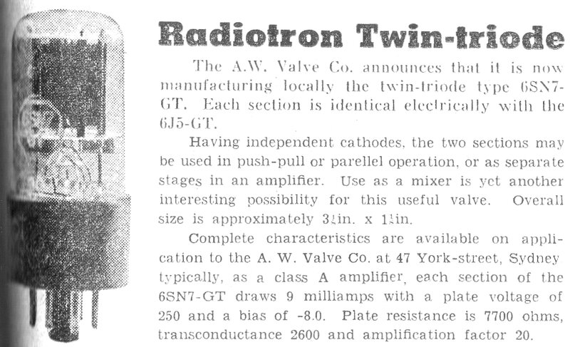
Australian manufacture announced in December 1945.
The 6SN7 is also developed from the 6J5. The output valve is an 807, which appeared at the beginning of the war, and is a development of the 6L6. The rectifier is the ubiquitous 5Y3.
Despite the WW2 design, there would be little point in building the receiver to cover the 42 to 50 Mc/s FM band, which existed at the time. Instead, it receives the 'new' 88 to 108 Mc/s FM band, introduced in 1946.

Rear view shows speaker terminals and aerial socket.
To save repetition, readers are referred to the two main circuits which make up this receiver:
Aside from that, the voltage amplifier and power supply are completely conventional.
Under view. Even two of the potentiometers are the correct vintage.
Note the sub-chassis for the earthy end of the 7193 circuit.
I decided to use all "Junk box" parts, since it was really just a test receiver. However, it worked so well that I decided to put a bit more effort into it. I'm very pleased with the results; not just in appearance, but the performance and sound quality. The chassis came from the free pile at the HRSA some years ago, and the top was quite rusty. It once a had a 2" CRO built on it; I suspect a kit, given the quality of the labelling and hole punching. Wire brushing it and then painting in grey epoxy made it quite presentable. All the other parts were randomly taken from my stock. The dial is period correct, being a Jackson 6-36. This incorporates a dual ratio drive; 6:1 and 36:1. Tuning is exceptionally smooth..
The Circuit.

Circuit of the receiver. Note the older style valves.
Super-Regenerative Detector.
Heart of the receiver is of course the
super-regenerative detector, which is built using the successful 7193 circuit.
This is the recently improved version, which includes chokes for the heater
supply. These provide a much stronger oscillation, which allows a tighter
aerial coupling and more effective operation of the stabilising circuit.
The three chokes are the usual quarter wave design. That is, 75 cm of 26
(approx.) gauge wire wound on a 6.5 mm or thereabouts, plastic former.
The tuning condenser is a porcelain type,
with a capacitance range of about 4.7pF to 32pF. The aerial coil is the
usual four turns of 1.6mm tinned copper wire, air cored, with a diameter
of 10mm.
My now standard grid leak regeneration control is used here. The automatic stabilising characteristic means that the adjustment is non-critical, and the detector performs consistently over a wide supply voltage without requiring adjustment. Also, for most of the time, no adjustment is required, as the receiver is tuned from one end of the band to the other. In its present form, it does not allow for complete cut-off of the oscillation, but I have not found any reception conditions which actually require that. Astute readers will note the regeneration pot is 1M instead of the 2M usually used previously. The 1M pot was to hand when I built this receiver, and so far its control range has been found to be adequate. One difference I have incorporated was an adjustable grid leak. This allows quench frequency to be adjusted over an extra range, which the normal regeneration control does not allow. The previously used 270k resistor is now comprised of a 150k isolating resistor and 250k pot. Adjustment is thus 400k to 150k. With the control in mid position (125k), the grid leak is 275k. This mid position setting provides the same performance as the original fixed resistor. In actual fact, the resistor in the test receiver measured 300k. As it happens, the use of a 1M regeneration pot means that it too is roughly centred, to obtain the original test receiver performance. In that set, the total grid resistance was 811k for best reception. We can see that with both controls in mid position (500k + 125k) and the 150k isolating resistor, the total grid resistance is 775k, which is close enough to the operating conditions of the test receiver.
The reason for including the 150k resistor, and not just using a pot alone, is because of the layout of the receiver. To extend a wire from the 7193 grid down the chassis, to the pot, could cause all sorts of problems, and would be poor VHF practice. The grid is live at VHF, and the inductance and stray capacitance could cause strange results. By including a portion of the required resistance right at the grid connection, only the quench frequency travels down to the pot. This being virtually in the audio spectrum is not critical. Beyond the frequency control pot, the quench frequency is bypassed by the 0.1uF, so the wiring to the regeneration control is also non critical.

Close up of the VHF part.
It took quite a lot of thought as to how to mount the 7193. There wasn't enough chassis room to mount it horizontally, as it had been in the test unit. The grid cap of the 7193 needs to be near the tuned circuit. It all came down to the position of the tuning capacitor being determined by the dial design. From here, a sub chassis was made to support the tuning capacitor and coil, mounted to the side of the 7193. Under the chassis, another sub chassis supports the valve socket, and the three chokes. A short length of braid earths this to the chassis. A connection also exists through the brass spacers which support the sub chassis.
Voltage Amplifier.
Since the 7193 only outputs a few hundred
millivolts of audio, a reasonably high gain audio stage is needed to drive
the output stage to full power, with some reserve. For the correct 'feel'
of the volume control, the output should start to overload with the volume
control a bit over half way up. This gives sufficient reserve for very
weak signals.
Keeping with the WW2 theme, my first idea here was to use a 6J8 triode hexode frequency converter as a two stage audio amplifier. Radio & Hobbies had been using this valve in a similar manner with some of their small receiver designs. The hexode was operated as a pentode regenerative detector, with the triode as an audio amplifier. Of course, the 6J8 was never designed to operate like this, but the more appropriate 6F7 was not made in Australia, and with the onset of war became very difficult to get. Hence, the use of valves in applications they weren't intended for. In essence, the scheme apparently works well enough, because the triode grid coupling into the hexode electron stream (at grid 4) is not high enough to be problematic. At first glance the 6K8 could be used similarly, until one takes a closer look. Here, the triode grid injects into grid 1 of the hexode. In this instance. the interaction between the triode and hexode would likely be too great to make the scheme practical.
Anyway, a circuit was made up with the
6J8. The hexode section worked quite well, but troubles were found with
the triode. The triode grid was producing a positive voltage with nothing
connected to it! To cut a long story short, there was an internal short
between the triode grid and cathode. Since I had very few 6J8s in my collection,
I felt it unwise to pursue this, since I might need them for more important
replacements. A single 6J7 pentode worked quite well, but there wasn't
the reserve of gain required for a car set. What other two stage valve
could we use? The obvious choice was a 6SN7. The only disadvantage is twice
the heater current of the 6J8. It's true that a 6SL7 could be used with
its 300mA heater current, but again, that's an obscure type in my collection.
I've got a lot more 6SN7s.
The actual valve used is the Russian version
of the 6SN7, designated 6H8C. I used this simply because I had a couple
within easy reach.
As to the design of the circuit, I referred to the RCA Receiving Tube Handbook, which contains charts for the plate, cathode, and grid resistors of various valve types used as resistance coupled amplifiers. A circuit was built up using the 6SN7 data. Gain per stage is about 15, so the entire stage gain is about 225.
Normally, I would put the volume control
at the input to the voltage amplifier, but with the high gain, I felt it
better to put it between the two triodes. Importantly, with the first stage
always operating at full gain, the output of the 7193 is not high enough
to overload it.
The advantage of placing the volume control
in the middle is less noise and hum. If the volume control is at the input
of the first stage, you are getting the full noise and hum of that stage,
even with the volume control at minimum.
The choice of cathode bypass and coupling
capacitors are not critical. I used what was to hand. Too high of a value
can lead to low frequency instability, and too low can result in reduced
low frequency response. The values I used are very typical.
Further quench filtering is provided by the 820pF capacitor across the volume control. It could have equally been connected from the first triode plate to earth, but connecting it across the volume control means it can have a lower voltage rating. Quench filtering is just sufficient to prevent the audio amplifier being overloaded at full volume.
This stage worked well immediately, without having to change anything or dealing with any instability problems. The gain measured exactly as per the RCA data.
Output Stage.
This used my recently designed 807 circuit
using a 100V PA line transformer, with cathode feedback. Two changes were
made, however. Since I had no more M-1120 line transformers, I had to use
something else. Going through my speaker transformer collection, I found
a couple of unbranded 100V line transformers rated at 8W. I can't remember
exactly what they came from, since I've had them for about 30 years. An
interesting feature is that power output is determined by tappings on the
secondary, rather than the primary. As long as the ratio is correct, this
should work just as well. The 8W rating would suit the 807, provided a
suitable impedance ratio was available.

Top view shows all the above chassis parts. Note the 100V line transformer.
A slight change to the 807 operating conditions
was necessary because of the power supply limitations. The original circuit
required 265V at 80mA. With the power transformer I decided to use, the
B+ voltage was likely to be around 230V, and limited to 60mA.
With the particular line transformer,
the highest non distorted output was with the 2W tapping feeding an 8 ohm
load. Here, we had 11.7V p-p into the load, which equates to 2.13W.
This is quite a drop from the 5W of the
original circuit, but not surprising. The difference between 235V and 265V
might not seem like a lot on paper, but the power output is very voltage
dependent. I first learned this with the Model T radio, using 6AQ5s. As
well as the B+ voltage reduction, the cathode current had to be also reduced
from 80mA to at least 60mA. Furthermore, the 100V line transformer I used
is not an M-1120. The available impedance ratios are not identical, and
it is not known to what extent the DC saturation problem might exist.
A recommendation for the 807 is screen and control grid stopper resistors to prevent any oscillation. Here, I have used 100 ohms for the screen grid, and 5.6k for the control grid. With the lower power operating conditions, it probably wouldn't be a problem, but is good practice to include these components. Remember, the 807 has a transconductance of 6 ma/V, which is fairly high for this era of output valve. Incidentally, anyone following my notes on the 807 will know that the 6L6 can be used in this circuit without any electrical changes.
Ultimately, best performance with the 235V
B+ supply, was with a 5k load impedance, and -14.4V bias. As a result,
the cathode resistor now needs to be 360 ohms. Since this is not a preferred
value, I used 330 ohms. Two 180 ohm resistors in series would provide the
exact value. Normally, it would be bad practice to err on the lower value,
but there is absolutely no danger of exceeding any ratings of the 807.
Total cathode current is 43mA.
So, we can see that with an actual plate
to cathode voltage of 221V and cathode current of 43mA, the 2.13W into
the load is pretty good, especially with the 'wrong' transformer. It is
well to remember, this is the power into the voice coil, instead of the
speaker transformer primary, as valve data usually states. This is why,
for example, you'll never actually get 4.5W from a 6V6 into a voice coil,
despite what the data says.
Overall sensitivity of the amplifier from
the grid of the first triode is 42mV rms. It might seem overkill to use
such a large output valve, when a 6V6, 6F6, 42, etc. would do just as well
with these operating conditions. But - I have a lot more 807's than any
of those other types!
I also wanted to prove the 807 circuit
in a built up form. One other thing, which might see me using more 807's/6L6's
in the future is the sound quality. I first noticed this when I built up
a six valve TRF receiver about 30 years ago, using a 6L6. I certainly don't
believe in most of the pomp that the audiophool crowd puts forth, but the
807/6L6 does sound very nice. In fact, I would say this is the best sounding
medium power amplifier circuit, which works with PA line transformers,
that I've yet heard.
Power Supply.
The power transformer is a N.O.S. type
of unknown brand.
The B+ secondary is 225V a side, at 60mA.
The rectifier heater winding is 5V at 2A, and the 6.3V heater winding is
rated at 3A.
To keep the 807 plate voltage as high
as possible, the speaker transformer is fed from the 5Y3 cathode directly.
While the ripple voltage is fairly high at this point, it does not mean
the output is full of hum. That's because of the high plate resistance
of a beam tetrode (or pentode). Instead, the filtering of the screen grid
supply is what counts. Here, an ordinary RC filter is used with a 2.2k
resistor and 32uF capacitor.
While some hum is evident with headphones,
it is virtually inaudible with a speaker. An extra stage of filtering would
be required to remove it completely, but the trade-off then is a further
reduction in B+ voltage.
The 6.3V heater supply is run around the chassis as a twisted pair. One side is earthed at the 7193 socket. Using the chassis as an earth return for the heaters is not good practice, since a 50 cycle current then flows through the chassis, and can be induced into the earth returns of other circuitry in the receiver. The chassis is not of an infinitely low resistance as one might think.
I prefer to include a fuse, instead of relying on the rectifier to fail open circuit, or the transformer windings to go up in smoke, should there be a short circuit. For this purpose, a 375mA time delay fuse is connected in series with the mains supply.
Adjustable Quench Frequency.
This is the first receiver where I've
made the grid leak a user adjustable control. Previously it has been necessary
to select this resistor on test, with the value being selected to provide
minimal intermodulation distortion, with the regeneration control adjusted
normally. Certain program material might require the quench frequency to
be shifted a few kc/s, to remove an annoying beat. On its own, the regeneration
control will provide this adjustment, with the quench frequency increasing
with an increase in regeneration. The question was, is it better to have
a high value grid resistor, with a low quench frequency as default, and
then increase the regeneration to increase the quench frequency as necessary?
Alternatively, should we have a low value grid leak, with a high quench
frequency as default, and use the regeneration control to reduce the quench
frequency? Providing a user adjustable control would allow this to be determined
over a range of signal strengths, and receiving frequencies.
Sound quality improves with an increase in quench frequency. The trade-off is that as quench frequency is increased, the sensitivity and audio output drops off. Generally, for FM stereo, a quench frequency of around 36 kc/s is about the lowest, to give reception reasonably free of the stereo subcarrier intermodulation artefacts. Around 50 kc/s gives better sound quality with less distortion.
A further observation is that the stronger the signal is, the more problematic the intermodulation distortion and stereo subcarrier beats become. Therefore, a higher quench frequency gives better sound quality for stronger signals.
Regeneration.
Another factor is that adjusting the regeneration
for highest sensitivity can result in overload on strong signals. This
shows up as more broad tuning, unable to find the best point for good slope
detection. The regeneration has to be increased to reduce sensitivity.
And, as it happens, the quench frequency increases, improving the sound
quality.
The method of regeneration control I've used with all my valve super-regenerative receiver actually works out very well. That is, regeneration is controlled by adjusting the grid bias of the detector. Since quench frequency increases with the amount of regeneration, it so happens that with weak signals the regeneration is minimum, which provides a low quench frequency, and highest output. Being a weak signal, the intermodulation artefacts resulting from a low quench frequency are not problematic. Conversely, with a strong signal, when the regeneration is increased to prevent overload, the quench frequency is raised, so that the intermodulation artefacts which would be problematic are automatically reduced. The otherwise reduced audio output is counteracted with the increased signal strength.
With all that being said, my conclusion is the adjustable grid leak is not really necessary. If the grid leak is selected for good reception on a weak signal, it is only necessary to adjust the regeneration for best reception. With this receiver, the quench varies from 25 to 70 kc/s with adjustment of the regeneration control. This is with the quench frequency in the minimum position (grid leak = 406k). With the quench frequency set to maximum (grid leak = 150k), the regeneration control varies the quench frequency from 23 to 155 kc/s.
A point of query with the 'new' method of regeneration control is that since it cannot take the valve to cut off, are we missing out on sensitivity? Tests were done to give a definite answer to this. With the receiver set to a weak signal, the regeneration was set by an external power supply for optimum reception. Grid voltage at the 0.1uF capacitor was measured at about -7.4V. Taking it more negative did not improve sensitivity, but merely cut off oscillation altogether. The external power supply was then disconnected, and the 1M pot adjusted for optimum reception. Guess what - the voltage was the same, and there was enough adjustment available.
Performance.
Frequency range is 85 to 147 Mc/s. The
full FM broadcast band is covered, along with the aircraft band, and part
of the 2m amateur band. Sensitivity is such that 1uV with a deviation of
40 kc/s can just be heard. The signal needs to be up around 10uV to become
listenable.
There is a slight reduction in sensitivity
at the low frequency end, because of the capacitive aerial coupling.
With a reasonably strong signal, and careful
adjustment of the regeneration and quench frequency controls, sound quality
is really good. The use of a slope detecting super-regenerative detector
is not obvious, and few would be able to pick it. The quality of the speaker
is important too. For this receiver I am using a Boston CR7.
