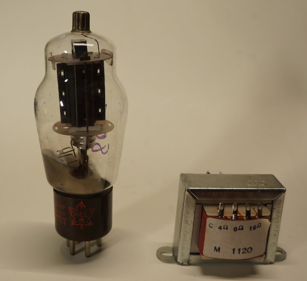
The combination of 807 and M-1120 worked rather well.
The combination of 807 and M-1120 worked rather well.
This article looks at designing an audio
output stage using an 807 valve, as a preliminary thought to using one
in my future Jeep
radio. I have a plentiful supply of 807's looking for a use, and the power
output would be about right for a radio in an open vehicle. With the output
valve decided on, an output transformer is of course also required.
"Proper" valve output transformers are
manufactured in the modern day, but they're expensive. A much cheaper,
and more readily available kind of audio transformer, is the P.A. line
transformer. These are intended for public address systems operating with
a 100V line.
100V Line Systems.
For large P.A. systems, and/or systems
with long cable runs, simply using 8 ohm speakers becomes impractical.
For example, with an 8 ohm speaker at the end of a 100m cable, the resistance
losses in the cable would be excessive, unless the cable had a large cross
sectional area (expensive). Adding more speakers in parallel will further
increase that loss. Furthermore, with multiple 8 ohm speakers in parallel,
the load impedance becomes impracticably low for the amplifier. One could
wire the speakers in series parallel combinations to present a more suitable
load for the amplifier. However, wiring speakers in series results in poor
damping, unless they are in the same enclosure. Also, if speakers needed
to be deleted or added later on, the whole thing has to be reconfigured
to maintain the correct load, and same volume from each speaker.
A much better way to implement this is
to operate at higher voltages and impedances. As we know with power transmission,
higher voltages mean less losses in the transmission system. For any given
power, the current decreases as the voltage is increased, which means wiring
resistance has less effect.
In Australia, early systems of this nature
were 500 or 600 ohm systems. Each speaker presented a 500 or 600 ohm load
to the system by means of a transformer. The amplifier would have multiple
secondary tappings on its output transformer to suit the load. For example,
if there were four 600 ohm speakers, the 150 ohm secondary tapping would
be used. As should be obvious, a few ohms in the wiring resistance will
be negligible against 150 ohms.
This method gave way to the constant voltage 70V or 100V line systems which are still used. Here, the amplifier is designed such that at full output, the voltage is 70V or 100V depending on the system. That is, if a sine wave is fed into the amplifier, 70 or 100V appears at the output terminals at full power. An important difference is that because solid state amplifiers are now used, the output impedance is very low. This means the output voltage will not drop as more speakers are added to the system (within reason).
In common with the 500/600 ohm system, each speaker is fitted with an individual transformer. However, now the transformer is more of a power matching device. The power to the speaker can be varied simply by selecting a suitable turns ratio. In this regard, the transformers are now labelled in terms of power, rather than impedance. Of course, the transformer is still an impedance matching device, but defining it in terms of power makes it easier to design a system. For example, if the amplifier was 50W, there could be ten speakers in the system, each with their transformers wired with the 5W tap selected. One does not have to enter into any impedance calculations. It's simply a matter of adding up load powers.
100V Line Transformers.
Of interest here are the speaker transformers.
Most are fitted with at least two primary tappings; sometimes more. The
secondaries are always 8 ohm, but may also include tappings for 2,
4, or 16 ohms. Conveniently, when the primary impedance is calculated,
it happens to be a good match for many types of output valve. Depending
on the transformer, primary impedances might vary from 250 ohms to 30k.
Indeed, many valve electronics enthusiasts
in the modern day have adapted them for the purpose. In Australia, they're
readily available from Jaycar and Altronics, and inexpensive.
The impedance can be determined from the
power rating, using the formula for power, P = V^2 / R.
We know what P and V is, so re-arranging
the formula will give us R.
Now, R = V^2 / P. For 100V transformers,
impedance is 10,000 / P. For example, if we want to know the impedance
of the 20W tapping, R = 10,000 / 20. That gives us 500 ohms. Where the
transformer is rated only for 70V systems, V^2 = 4900.
DC Saturation.
P.A. Line transformers are made with interleaved
laminations. That means there is no air gap. A problem arises if DC is
passed through the windings. The core will become magnetised, and begin
to saturate. This reduces efficiency and restricts output. When the transformer
is used in the plate circuit of a single ended valve output stage, there
might be typically 45mA of DC flowing. "Proper" single ended valve output
transformers are constructed so that the E-I laminations are all in the
same plane, butted up against each other with an air gap. This prevents
core saturation. Typically, the air gap is a thin piece of paper.
The result is that using a P.A. line transformer
as a valve output transformer can result in distortion and poor frequency
response, depending on the degree of saturation. The lower the DC and the
greater the core size, the better the results will be.
The problem does not exist in push-pull
stages, since the direction of the windings ensures the magnetisation cancels
out. However, there's still one remaining limitation, and that is the turns
per volt ratio. In a constant voltage 100V system, this is probably not
critical, but in a valve output stage, strange things happen if there is
not enough inductance (i.e. not enough turns per volt). The sound is shrill
and unpleasant to listen to. Some improvement can be had if the output
stage is changed to a triode, but efficiency and power output suffers.
Some enthusiasts have mentioned dismantling
the transformer and rearranging the laminations and providing an air gap.
The problem then is the inductance is inadequate, and if the turns per
volt was already a bit on the low side, it will be even more so now. I
know because I have tried it.
The M-1120.
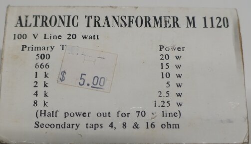
They're not normally this cheap, but this particular transformer
was being sold as clearance stock.
The transformer chosen for this experiment
was the Altronics M-1120. This is a 100V line transformer rated at 20W.
Conveniently, the impedances are listed on the box label. For single ended
class A use, the 807 is designed for a 2.5k load. With the choice of tappings
available, the 5W (2k) and 2.5W (4k) would be the ones to experiment with.
Maximum output from an 807 is 6.5W, so it makes sense to use as large a
transformer as possible. A larger core will saturate less than a small
one; hence the choice of the 20W transformer.
The core size of this transformer is similar
to a good quality 5W single ended valve type. Clearly, the core size can
be a lot smaller when there's no DC component.
Now, just to clear up a possible point of confusion. The transformer core is rated for 20W. As the impedance taps increase, the power shown decreases, and by the time we get to 8k, it's only 1.25W. However, in actual fact, we can feed 20W into the 8k tap if we wanted to - the core is rated for it. The 1.25W is simply the power output when fed from 100V.
The 807.
Perhaps not well known is that the 807
is electrically the same as a 6L6. The characteristics and curves are the
same. The difference is that because of the plate connection being to a
top cap for the 807, this valve can be run at a higher plate voltage than
the 6L6. It was also more suited to transmitter use, since the top cap
provides a more direct connection to the plate. The 807 is fitted with
a UY-5 base, rather than the octal type used for the 6L6. While the 6L6
and 807 were used in the same audio applications, the 807 was more suited
to transmitter use. It would appear the UY-5 base would be less lossy in
this regard, since the grid pin is spaced furthest from any of the others.
Type 1625 is a military type, identical to the 807, but has a 12.6V heater,
and a 7 pin base larger than the usual UX-7 type. Type 6BG6 is a TV line
output valve, once common in the U.S., but obsolete prior to the arrival
of TV in Australia, and was never used here. Its class A characteristics
are virtually the same as the 807. The 6BG6 has an octal base. Therefore,
the following experiment is also applicable to the 6L6, 1625, and 6BG6.
| Vp | Ip | Vg2 | Ig2 | Vg1 | ZL | Po |
| 250 | 72mA | 250 | 5mA | -14V | 2500 ohms | 6.5W |

From the AWV Radiotronics issue 90, this data shows operation at
other voltages, and in push-pull.
First Experiment.

Test circuit for the 807 and M-1120.
The circuit was powered from a BWD 215A
variable power supply. This also provides a variable negative supply for
bias. Input signal was from a General Radio 1304-B beat frequency oscillator
operating at 1 kc/s. Since this has an output impedance of 600 ohms, a
100k resistor was added in series, to simulate the input as it would be
from a preceding valve voltage amplifier.
Applying the input of a low impedance
signal generator to the grid circuit directly can give erroneous results
in this kind of circuit, and lead one to believe the circuit can output
more power than it really can. This is because a low impedance source is
capable of driving the grid positive, if the peak voltage is greater than
the standing negative grid voltage.
The power supply was set up as per specifications;
i.e., 250V B+ and -14V C-. Both 2.5W and 5W tappings were tested for maximum
output.
| Tapping | V into 8 ohms | Po | Input V |
| 2.5W (4k) | 15.7 p-p | 3.85W | 23.6 p-p |
| 5W (2k) | 17.4 p-p | 4.7W | 28.3 p-p |
As expected, the 5W (2k) tap provided more power, but it did so at the expense of more distortion. Nevertheless, considering this transformer was not designed to have DC flowing through it, the results were surprisingly good.
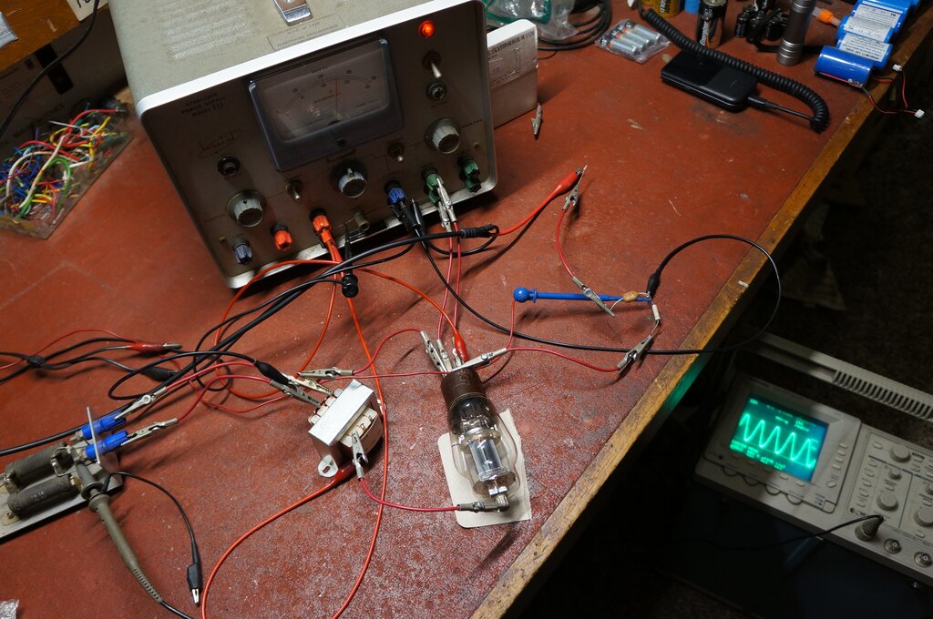
Test set up.
Improved Circuit.
Negative feedback improves distortion,
although at the expense of gain, so this was next considered. Also, on
the subject of core magnetisation, if we were to put some DC through the
secondary winding with the correct polarity, it should offset some of the
magnetisation caused by the primary winding. The next experiment implemented
both of those ideas.
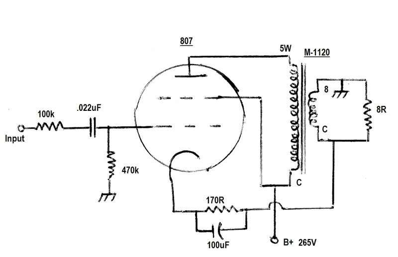
Final Circuit.
Here, the entire cathode current is fed
into the secondary winding (about 80mA). At the same time, the full secondary
voltage is fed into the cathode, providing a high degree of negative feedback.
The final circuit included cathode bias as shown.
| Tapping | V into 8 ohms | Po | Input V |
| 2.5W (4k) | 15.7 p-p | 3.85W | 39.4 p-p |
| 5W (2k) | 17 p-p | 4.5W | 47 p-p |
| 5W (2k) | 18 p-p | 5W |
There was an obvious reduction in distortion
with the feedback circuit in place. Further experimenting found that more
power output could be had without increasing distortion by increasing the
grid voltage to -15.2V. Now, output was a genuine 5W into the 8 ohm load.
This is a very satisfactory result considering
the 'wrong' transformer is being used.
Because of the very high degree of feedback,
the input sensitivity is about halved. With a B+ of around 250V it should
not be difficult to get a voltage swing of at least 50V p-p from the preceding
stage. Obviously, the 100k resistor would not be included.
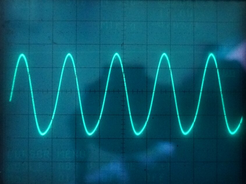
Output waveform at full power. Some slight distortion can be seen
towards the bottom peak.
Cathode Bias.
Fixed bias is not usually convenient,
since the power supply has to produce a negative voltage. If the negative
supply fails, the valve is likely to pass excess current and my be damaged.
Cathode bias was therefore tried. Calculations indicate around 175 ohms
for the cathode resistor. A rheostat and 100uF bypass capacitor were introduced
into the circuit for testing. As it turned out, the ideal cathode resistance
was 170 ohms. This gives -15.2V bias at full output. When there is no signal,
bias is 13.9V. Of course, since the bias voltage is subtracted from the
B+, this needs to be increased to 265V.
Using the 2.5W Tapping.
The 2.5W (4k) tapping was tried with the
feedback circuit, but with a higher bias. With a grid voltage increased
to -18V, power output was 3.75W. As can be seen, there is only a loss of
100mW from when using -14V bias, but distortion is reduced, as is B+ current.
This was 63mA at full output, and 58mA at no output. This should not be
surprising, since the lower plate current suits the higher impedance load.
Although the cathode resistance was not
measured for this test, it calculates to 286 ohms. (Two 560R 1W in parallel
would be suitable).
The choice of which tapping to use comes
down to the available power supply. Where the power supply can supply 90mA,
use the 5W tapping and obtain 5W output. Where the power supply can only
supply 63mA, use the 2.5W tapping, and obtain 3.75W.
| Tapping | B+ voltage | B+ current (full o/p) | B+ current (no o/p) | Vg1 | Po |
| 2.5W (4k) | 268 | 63mA | 58mA | -18 | 3.75W |
| 5W (2k) | 265 | 89mA | 80mA | -15.2 | 5W |
The heater requirements are 6.3V at 900mA for the 807, 6L6, and 6BG6. For the 1625, the heater is 12.6V at 450mA.
Conclusion.
The results were successful in getting
a 20W line transformer to work with an 807. However, it must be realised
that more undistorted power output could be obtained with a correct transformer.
Efficiency is less than when a proper output transformer is used. For example,
as far as the 3.75W version of this circuit is concerned, a 6V6 with a
proper transformer would achieve that with half the heater current, about
10mA less B+ current, and less distortion.
It's really a case of wanting to build
a cheap output stage with one of the valve types listed, where true hi-fi
quality is not required.