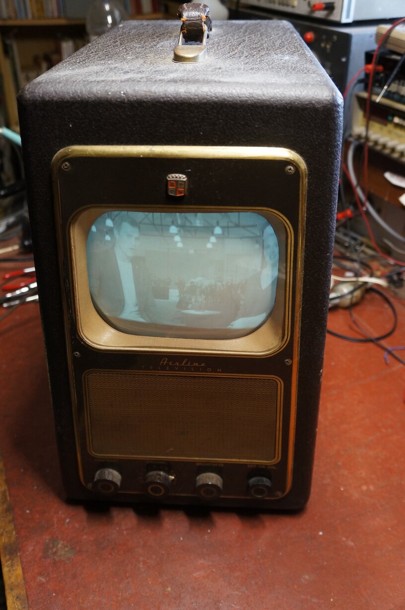
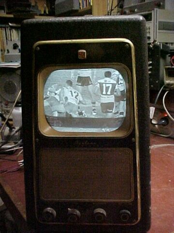
From left to right the controls are: Contrast, Channel, Brightness and On/Off Volume.
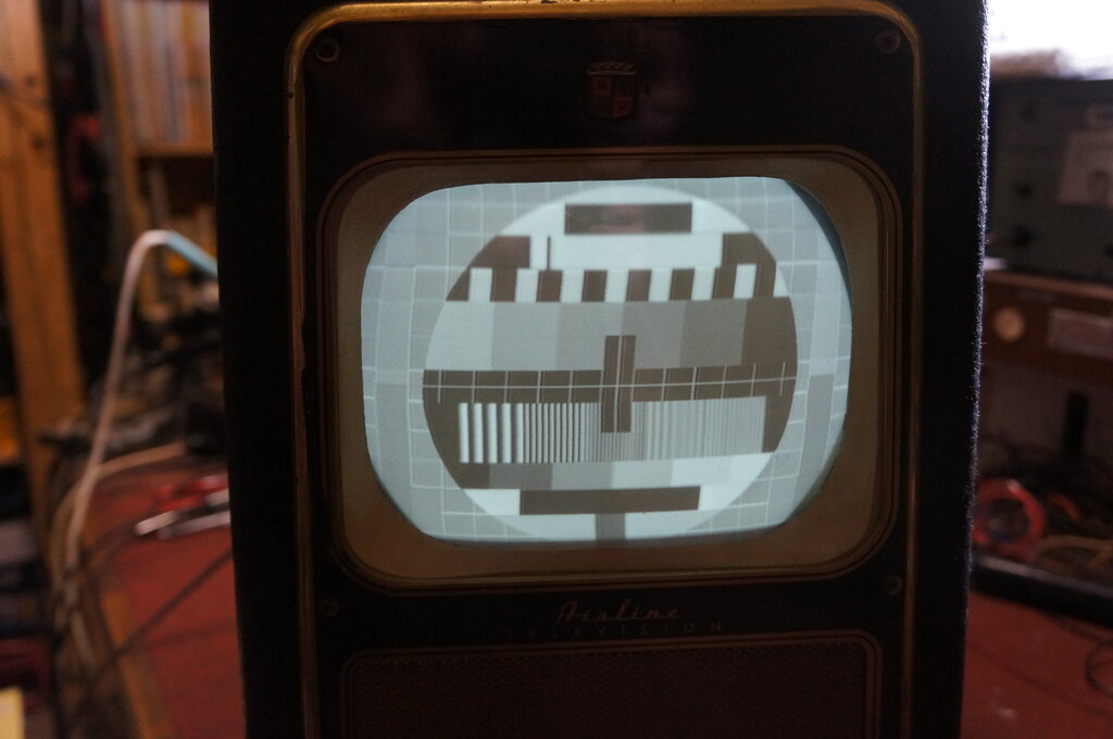
One of the first things I bought off eBay, back in 2003, was this Airline 7" TV from 1949, model 84GE-3011A. It is a rebadge of the well known Sentinel 400-TV, sold by the Montgomery Ward chain of stores. Airline was their in house brand. There is also a version of this set in a table cabinet with radio and gramophone, model 94GSE-3018A.
From left to right the controls are: Contrast, Channel, Brightness
and On/Off Volume.
Background to Electrostatically deflected
TV sets.
I'd always wanted a commercially made
electrostatically deflected TV set, having built the Radio Television &
Hobbies 5" 5BP1 TV set back in the mid 1980's. The advantages of electrostatic
deflection are many, including simple resistance coupled deflection circuits
and low power consumption. No weird deflection yokes and line output transformers
to cause problems when they fail. It is thus easy to build a complete TV
set with no hard to get parts, as I found with the 5BP1 set.
In the U.S where TV had been going alot
longer than in Australia, electrostatically deflected sets had existed
since the start of electronic TV there. Indeed, the 5BP1 and 5BP4 tubes
which appeared in 1939 were designed for the new television service. These
were used in various commercially made and kitset receivers such as those
produced by RCA (TRK5), Andrea, Transvision, Meissner, etc. Smaller sets
were made with 3" tubes such as 3KP1 and 3KP4. The well known Pilot TV37
portable is one such example. However, post war the most popular screen
size for electrostatic sets was 7", using a 7JP4 or 7EP4. At the height
of popularity in the late 1940's, there were numerous table, and suitcase
or oscilloscope shaped portables with a 7" electrostatic tube. The well
known examples include Hallicrafters T54, Tele Tone TV149, Motorola VT71,
and the Sentinel 400-TV which is the set to be described here. By this
time in history, 7" electrostatic sets were intended as a cheap second
or portable set as the size of electromagnetically deflected tubes was
now up to 16" and was preferable for the main set in the house.
In Australia, television started in 1956
and by this time electrostatically deflected sets were obsolete. Here,
we started with 17" and 21" electromagnetically deflected picture tubes.
However, due to the high cost of TV sets, it was common for enthusiasts
to build up sets using 5BP1 or VCR97 CRT's which were plentiful on the
disposals market. These tubes were commonly used in wartime oscillographic
equipment such as radar indicators.
With the experience I've had with my homemade
5BP1 TV set, electrostatic deflected picture tubes and associated circuits
were no stranger to me.
In more recent times, I have built two
more electrostatically deflected sets. One is another
version of the 5BP1 set; this one being more faithful to the original
magazine project, and a 2"
video monitor using a 902-P1, entirely of my own design.
My Sentinel 400-TV.
I acquired this set in October 2003, having
bought it off eBay. I got it cheap as the seller had listed it in the wrong
category, and thus few people saw it. The title was also misspelt which
prevented it being found in the search. To add to my luck, although I only
paid surface mail postage, it arrived two weeks later by airmail. I have
a good collection of U.S electronics magazines from the 1940's and thought
I'd have a look through to see if there was any mention of this set. Sure
enough, there was a whole article, complete with circuit diagram, in Radio
Electronics for March 1949. This issue can be found at worldradiohistory.com.
That solved the problem of getting the circuit at least.
My set was in pretty good condition cosmetically.
All was there except the 6AU6 video and sync separator valves. I noticed
that a couple of the 6SN7's looked like they'd been replaced, as they were
clean and the rest of the set had the usual amount of dust on everything.
Perhaps the previous owner had tried to get the set working, gave up and
put it on eBay.
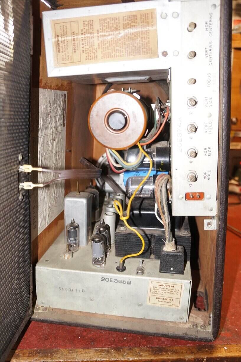
The set is built on two chassis, with
the RF chassis on the bottom of the cabinet and the picture chassis mounted
on the side of the cabinet. The two chassis connect together with a 12
pin Jones plug and socket.
Design of the 400-TV
First refer to the RF chassis circuit:
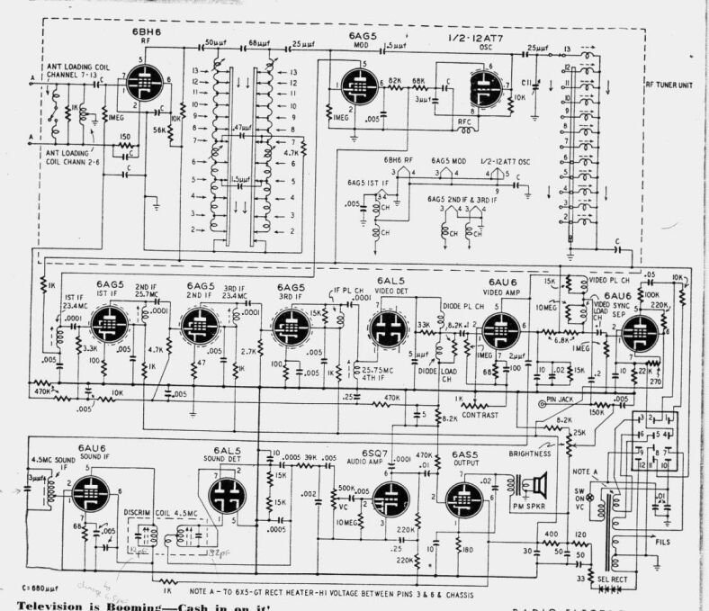
Circuit of the RF chassis. Nothing too unusual here.
Tuner.
Apart from some of the valve types not
common in Australian TV sets, the circuit here is not vastly different
to what one would see in local design.
The main difference is the tuner design.
It's a Sarkes-Tarzian incremental unit. The thing to catch the eye of the
Australian reader is the pentode RF amplifier and separate modulator (mixer)
and oscillator valves. By the time TV arrived here, this was obsolete technology.
Australian sets started off using cascode RF amplifiers using a twin triode,
usually a 6CW7 or 6BQ7. And by this time there was a range of 9 pin triode
pentodes for frequency conversion, such as 6BL8 and 6U8. Note that
only half the 12AT7 is used. This seems a bit wasteful as the second triode
just spends its life being cathode poisoned due to no cathode current.
A later version of the tuner uses a 6C4 instead of the 12AT7. The other
valve with half a section being wasted is the 6AL5 video detector.
So confident were the designers of this
set, that the intercarrier sound system would eliminate critical fine tuning
adjustment, no fine tuning control is provided on the front panel.
Video IF and AGC.
Note that the video IF is lower than the
standard Australian IF. It's at 25Mc/s. The video IF strip follows conventional
practice and feeds the 6AL5, which provides detected output and also simple
AGC. There is no AGC delay. The AGC system is typical of cheap sets and
suffers from being dependent on the average video signal, rather than the
sync pulse level. This means AGC voltage fluctuates depending on scene
content. There are no adjacent channel traps. This keeps alignment and
the design of the IF strip simple, but can be a problem in areas where
adjacent channels can be received.
The video amplifier is also conventional,
though by 1956 when TV had arrived in Australia, there were pentodes specifically
for video use, such as 12BY7 and 6CK6. Contrast control is by variable
cathode degeneration. As the contrast rheostat is turned to maximum resistance,
there is considerable negative feedback and thus reduction in gain. Again,
typical of cheap sets, but it is simple and does work well. The plate of
the 6AU6 feeds the CRT cathode in the usual way. AC coupling is used which
is nothing unusual.
Sync Separator and Black Level Control.
Following the video amplifier is also
the 6AU6 sync separator. It is very simple, relying on a sharp cutoff
pentode being biassed into its non linear region (note the high value cathode
resistor), and thus cutting off all the video signal except the sync pulses.
Despite the simplicity, there's a novel bit of circuitry added on here.
See the CRT grid connected to the 6AU6 cathode? It's used as a crude form
of DC restoration for the picture tube. Details were described in Radio
& Television News, March 1949, p 72. If the CRT grid was earthed, the
video stage and CRT would function like any other AC coupled set, where
the average picture brightness is always the same, regardless of scene
content. However, it so happens that the sync separator cathode voltage
increases with an increase in video signal. So, as scene brightness goes
up, so does the voltage on the 7JP4 grid, and vice versa. Therefore, the
picture will darken with a night scene for example, rather than remaining
at a fixed grey level. It is not true DC restoration, but more of an automatic
black level control that gives a similar effect. Not a bad compromise either,
as I found once the set was working. True DC restoration restores correct
black level on a line by line basis. It requires an extra diode (why didn't
they use the other half of the 6AL5?), or DC coupling from the video detector
right through to the CRT.
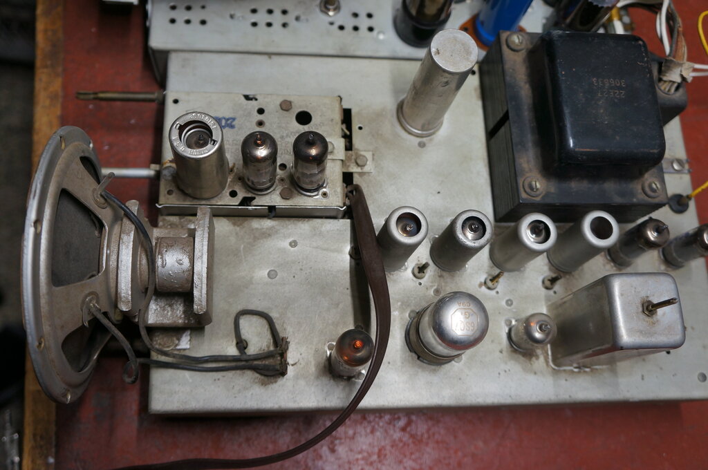
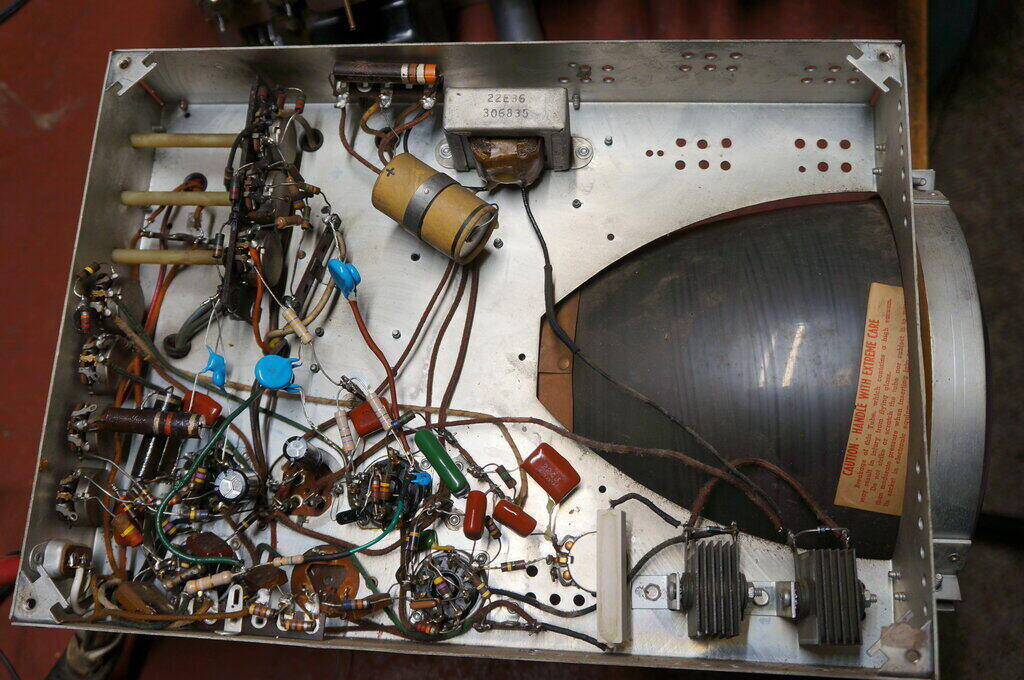
RF chassis. Note the tuner having three valves. The middle row of
valves includes the video IF, detector, amplifier and sync separator. The
bottom row has the sound IF, detection and output valves.
Sound and Power Supply Stages.
The sound stage is conventional, but the
6SQ7, 6AS5, and half wave selenium rectifier powering it would attract
the attention of the Aussie TV technician.
Intercarrier sound is used, and this was
among the first generation of American sets to do so. The 6SQ7 is a bit
out of place amongst the other modern seven and nine pin valves on the
chassis. The 6AT6 could have been used. Still, lots of octal valves look
nice in a TV set so I'm not complaining.
The 6AS5 is a valve very uncommon here.
It's one of those 2W audio output pentodes meant for 120V screen and plate
operation, so common in U.S TV sets. Here the valve is run off a 130V supply
from a half wave selenium rectifier, fed by the 115V secondary on the power
transformer. Normal practice using this type of valve is where the B+ is
250V, and the audio and IF stages are in series with each other, in terms
of DC supply.
The power supply uses a transformer with
the usual 6.3V heater windings, and a 115V secondary for B+ . This is also
typical of Australian practice, except for the rectifiers. Where an Australian
TV power transformer has a 115V secondary, it is fed into a full wave voltage
doubler to provide 250V DC.
The Sentinel approach is to use a half
wave rectifier to provide 130V for the audio and sync circuits, and a half
wave voltage doubler to provide 260V for the deflection circuits. The asymmetrical
loading of the transformer certainly won't contribute to efficiency, with
some core saturation and heating resulting.
They could have used a full wave doubler
with the same number of components. The set has no fuse which is not good
practice. Provided there's no shorts in the transformer itself or the heater
line, the 10R and 33R resistors feeding the rectifiers will act as fuses.
Now to the interesting part; the picture
chassis:
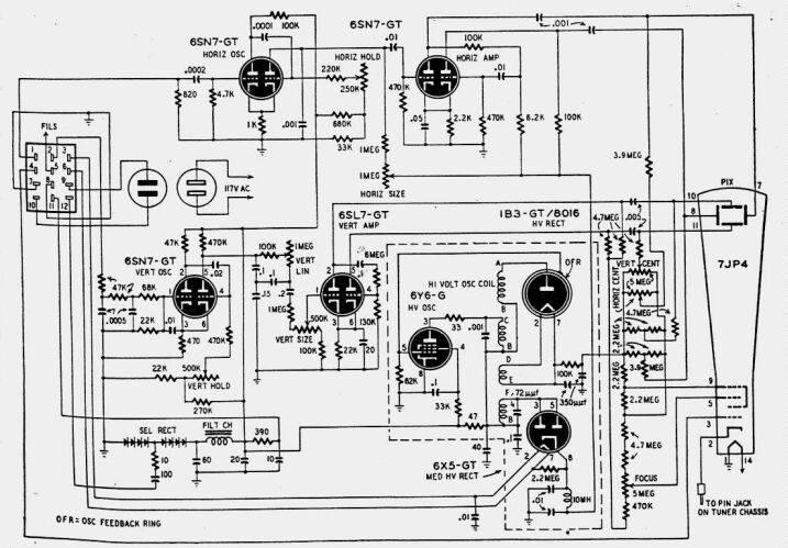
Typical of electrostatic deflection circuitry, this is the circuit
of the picture chassis. Note the simplicity compared to a set using electromagnetic
deflection.
EHT RF power supply.
To the average Aussie tech brought up
on nothing but small variations of electromagnetically deflected TV sets,
this part will seem quite unusual.
First, note how simple it is. No vertical
output transformer to go o/c, no line output transformer or yoke to develop
shorted turns and require exact replacements. Starting with the 7JP4 picture
tube, it is like any other oscilloscope tube except it's larger and has
white (P4) phosphor. EHT is around 5KV. The EHT comes from an RF oscillator
type power supply. While earlier sets used a high voltage transformer operating
at mains frequency, feeding a 2X2 or similar rectifier, there were disadvantages
with this scheme, especially as EHT requirements increased over the years.
With the usual turns per volt ratio used with iron cored transformers operating
at 50 or 60 cycle mains frequency, many thousands of turns of very
fine wire are required. Not only is this fine wire prone to breaking, but
keeping it insulated from the other windings and the transformer core is
a problem. There is also a safety issue. Such a power supply can easily
provide enough current to kill. Further, DC filtering requires high value
paper capacitors because of the low frequency, and invariable half wave
rectification used. The high capacitance not only makes for expensive capacitors,
but also adds to the shock hazard.
RF power supply. Valves are 6Y6, 1B3, 6X5. Spring around the 1B3
provides capacitive feedback to make the 6Y6 oscillate.
By the mid 1940's, RF power supplies had
become a popular way to obtain EHT. Running at high frequency means a small
air cored transformer with fewer turns can be used. The high frequency
also allows low value filtering condensers to be used. In this set they're
only 350uuF. And, the regulation is such that the voltage will drop considerably,
if someone gets across the EHT. Typically, a high power audio pentode or
beam tetrode is used in a self oscillating circuit. Typical valves used
are 807, 6L6, 6V6, or as used here, 6Y6. Positive feedback is obtained
from a winding on the transformer, or sometimes by a low value of capacitance
to the EHT winding as is the case here. You don't see the capacitor? It's
there in the form of a spring around the glass of the 1B3 EHT rectifier.
The plate of the 1B3 is the other side of the capacitor with the glass
being the dielectric. Feedback, and thus output voltage can be adjusted
by the position of the "OFR" (Oscillator Feedback Ring). The 1B3 heater
is fed off a separate winding on the RF transformer, as it's directly heated
with the cathode floating at 5kV. This is the same as with a conventional
line output transformer.
In this set there's also a second supply,
of about 760V produced. This comes from another secondary which feeds a
6X5. Again, note the low values of filter capacitance. The 6X5 heater is
fed from an isolated winding on the mains transformer, so as not to stress
the heater to cathode insulation. In fact there's a 2.2M resistor from
heater to cathode to keep both at the same potential. This 760V feeds the
horizontal deflection output and oscillator.
The RF power supply is powered from the
260V supply.
Across the 5kV supply is a voltage divider
made of high value resistors and preset pots. This supplies the DC for
the deflection plates to ensure the picture is centred on the screen, and
the screen and focus grid for the 7JP4. The bottom end of this voltage
divider feeds the vertical output stage at 700V. The horizontal output,
although using a similar voltage, cannot be fed from this point as it requires
more current than flows through the voltage divider.
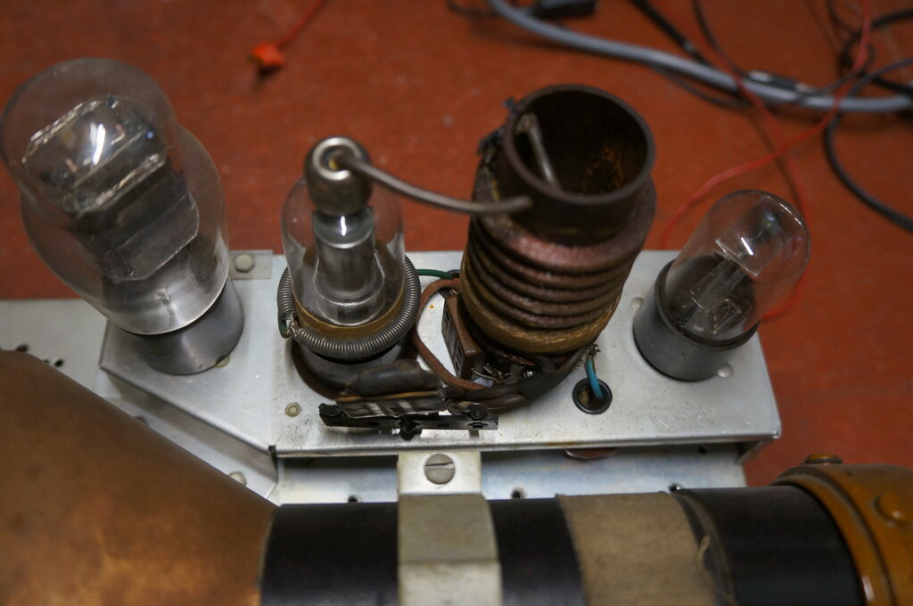
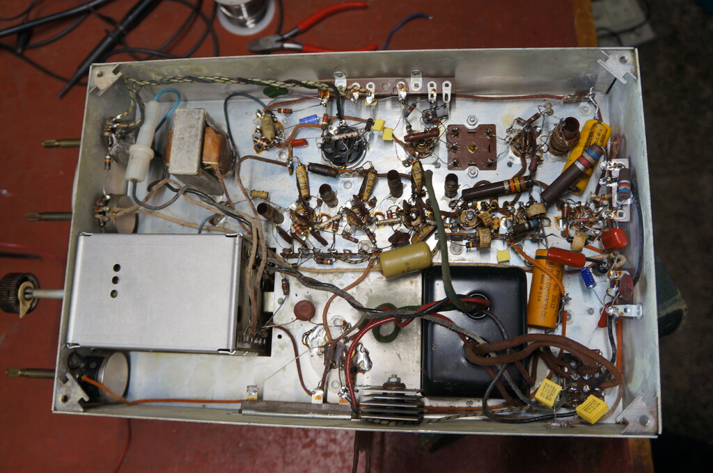
Top view of the picture chassis. The RF power supply is in the shielded
box, to the left of which is the 6Y6. The 6SN7's and 6SL7 are grouped together
on the other side. The 1B3 and 6X5 are inside the shielded box.
Vertical deflection.
Starting with the vertical section, a
conventional 6SN7 twin triode multivibrator is used. This provides a sawtooth
waveform, then amplified by a 6SL7 wired as a push pull amplifier. The
vertical plates of the 7JP4 are coupled to the 6SL7 by low value 6kV condensers.
Low values (i.e.. cheap, small) can be used because of the high impedance
of the deflection plate circuit; the plates being voltage driven and not
current driven. Note the 4.7M plate resistors of the 6SL7. Such high values
are used to obtain the high voltage swing required, and to further aid
this, they are fed from 700V.
Here, we can see the limitations of electrostatically
deflected CRT's. As screen size goes up, so does the deflection voltage
required, unless the deflection angle remains the same. However, this results
in a very long tube. Larger screens require more EHT. This reduces deflection
sensitivity as the electron beam becomes stiffer. DuMont was quite fond
of large electrostatic tubes in their prewar sets. The largest electrostatic
tube I am aware of is the 20AP4. It has a length of about 27". Needless
to say, such tubes are best accomodated in "mirror in the lid" cabinets.
As an example of the deflection voltage required, DuMont's prewar 14" set,
using a 14AP4, required a 1500V B+ for the deflection output valves,
operating as ordinary resistance coupled amplifiers. Despite the
practical size limitation, electrostatic tubes do have advantages where
only a small screen is required.
Horizontal deflection.
Turning now to the horizontal section,
again a 6SN7 is connected as a multivibrator. This feeds another 6SN7 as
horizontal output. Due to the higher frequency, even lower value coupling
condensers can be used to feed the deflection plates.
The horizontal oscillator is triggered
directly off the sync pulses. There is no AFC circuit. This is another
surprise for the local technician, given there were no commercially made
TV sets in Australia that did this. Horizontal AFC is seen as necessary
because noise pulses in the off air video are the same polarity as the
sync pulses (something inherent in the negative modulation system used
in Australia and the U.S.). An AFC circuit used with a horizontal oscillator
effectively makes the whole thing a phase locked loop. The oscillator frequency
is controlled by DC, the result of which is obtained by comparing the incoming
sync pulses with the frequency of the oscillator itself. The further the
oscillator drifts off frequency, the greater is the DC to bring it back.
The time constant of the DC filter is the key to the noise immunity. By
having it longer than the period of a few lines, high frequency noise is
ignored. For small screen cheap sets, AFC was not included. In reality,
the signal has to be pretty noisy for lack of AFC to become evident. The
small screen hides any minor noise triggering anyway.
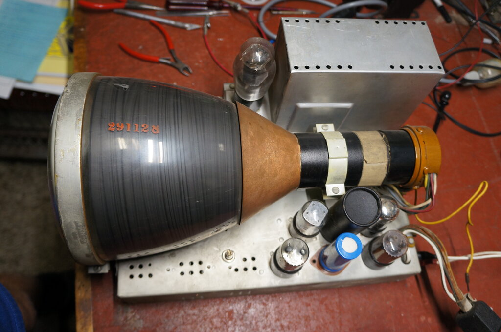
How the two chassis are arranged in the cabinet. Rather awkward
to set the CRT rotation correctly!
Restoration begins.
Having extracted the chassis, I could
see that set had hardly ever been serviced except for a few valve replacements,
and a 1.8M resistor which had been added to the EHT divider network, presumably
to compensate for other resistors going high and the serviceman being too
lazy to replace them.
I noticed the 6BH6 RF amplifier valve
had been replaced by a 6CB6. The channel knob was damaged from it slipping
on the splines of the tight tuner shaft, but looked repairable. And so
begun the tedium of desoldering and unpicking numerous paper condensers.
I found virtually all the resistors, while a bit high in some cases, were
not so far out as to be worth replacing. A later 7" set I restored (Admiral
17T1) also seemed to have all its resistors close to value. It seems American
resistors of the period must be quite stable, unlike the IRC horrors filling
the underneath of Australian radio and TV sets.
I also had to replace the rubber flex
that ran between the mains input socket and the switch, as it was hard
and crumbly.
Most of the work in restoring a vintage
TV set is in replacing condensers and resistors. Generally, I replace every
resistor over 100K and every paper condenser, unless it is a cathode bypass
and the cathode resistor is only up to a few hundred ohms. I leave electrolytics
in as I have so rarely found defective ones (in Australian sets at least),
although faulty ones are starting to show up as time goes on. I am now
replacing mica condensers in certain instances, since these are now old
enough to be causing intermittent faults (e.g. scratchy sound, intermittent
sync) as the plate material migrates through the mica.
After all that, usually all that is required
is a touch up of the presets, and local oscillator cores in the tuner.
Using an American TV in Australia.
However, this being a set for the U.S.
standard (system M) would need more to get it working here. Put simply,
to use a system M television on system B, as used in Australia, the following
things need to be done. 1) provide 120V by a stepdown transformer, 2) readjust
vertical hold and height to run at 50c/s, 3) retune the sound IF to 5.5Mc/s,
4) adjust local oscillator cores in tuner. The line frequencies of 15,734c/s
(U.S) and 15,625 (Aus.) are close enough that not even the horizontal hold
needs adjustment. If the set is a colour one, it will of course work with
a monochrome picture. Much more work is involved converting an NTSC colour
decoder to work on PAL. I have done it once with a solid state set and
it worked well. Not only does the chroma circuitry have to be retuned from
3.58Mc/s to 4.43Mc/s, but there's circuitry which has to be added to invert
the phase of the red colour difference channel on every second line. The
colour decoder then works in PAL-S. It is hardly worth the effort to add
a delay line to make it work in PAL-D.
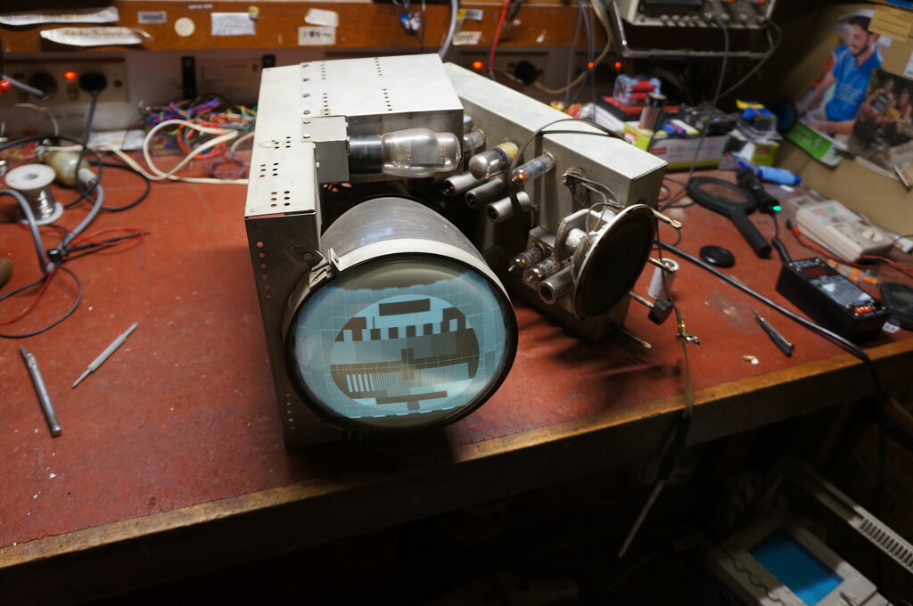
The two chassis can be run outside the cabinet, flat on the bench, as the connecting cable is just long enough. At the initial power up it was obvious this had been done before, as the CRT had been rotated so the picture was the right way up with the picture chassis in this position. As you can see from how the chassis is in the cabinet, the CRT is normally turned around to a bit over 90 degrees so the picture appears correctly to the viewer. Evidently someone had played with the set since it was last used.
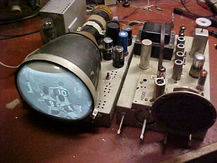
The connecting cable is just long enough to allow the chassis to
be connected together when flat on the bench. Needless to say, this pic
was taken once the set was operational, and before the CRT had been rotated
to the correct position.
Initial Testing and Retuning the
Sound IF.
Once I'd connected the aerial and plugged
the set into my UTC R44 240-120V stepdown transformer, I could tune in
some channels which were close enough in frequency to some of the U.S.
ones. Of course, there was no sound due to their sound being 4.5Mc/s above
the vision carrier, and ours being 5.5Mc/s. There wasn't enough adjustment
in the SIF or ratio detector transformers, so I had to replace their tuning
capacitors with ones of lower value. The ratio detector primary had 12pF
across it, but this needed to be lowered to 6.8pF. Likewise, the secondary
needed the 82pF replaced by 39pF. For the SIF coil, I removed the
3pF capacitor and this gave enough tuning range. Strictly speaking, the
video IF should be realigned to accommodate our wider video channel, and
to ensure the sound carrier is at the correct level for intercarrier reception,
but in practice it isn't usually required.
Sensitivity and general gain of the front
end seemed poor. Even with the contrast wound up the picture was still
lacking in good greyscale. I couldn't find any defective components around
the video IF or output, so then checked the valves. Some of the 6AG5's
were a bit weak, but one particularly so. I replaced it with a 6CB6 which
improved things. I couldn't be bothered looking for a 6AG5 as in this circuit
the difference is insignificant. Incidentally, I did try one of the 6AG5's
in the tuner's RF amp just to see; it was no better than the 6CB6 which
had been put there.
I found the B+ to be low. Mainly this
was due to the 100uF feeding the voltage doubler being low in value, but
there was also a worthwhile increase when all the three selenium rectifiers
were bridged with 1N4007 diodes. Selenium rectifiers are known for failing
as they age so I wasn't surprised. Normally, a series resistor should be
added when installing a silicon diode due to its much lower resistance,
but there were already series resistors which could perform the function.
The B+ did not seem excessively high.
Retrace Blanking.
Another annoying thing was retrace lines
being visible. This set, like all the other electrostatic sets I've seen
has no retrace blanking circuit. At certain brightness and contrast settings
one can reduce the problem but they seldom go away completely. And, with
today's field blanking interval filled with teletext and various other
signals, the problem is worse. With the Admiral 17T1 I'd restored, I developed
a simple but effective circuit which coupled one of the 6SL7 vertical output
plates into the CRT grid via a 100uuF condenser. This provided a negative
pulse, cutting off the CRT during vertical retrace. It worked so well with
the Admiral, I simply adapted it for the Sentinel. However, I found the
blanking to be excessive, causing shading on the left side of the picture.
I could have reduced the capacitor value, but instead I fed it into the
grid via a voltage divider. The wire between the 6AU6 sync separator cathode
and pin 4 of the Jones socket (which ultimately feeds the CRT grid) is
replaced by a 390k resistor. Pin 4 is fed the blanking signal which comes
from the 6SL7 plate (pin 2) via a 100pF 1kV capacitor and 680k resistor.
![]()
How to add retrace blanking.
I noticed poor horizontal linearity on the right side of the picture. I know that these electrostatic sets because of their cheapness often don't provide linearity adjustments, especially for the horizontal, but this was not acceptable. Eventually, I found I'd connected one of the deflection plate coupling condensers to one of the 6SN7 grids rather than the plate. This sort of mistake is not uncommon due to the tedium of large scale component replacement. This fixed, I turned my attention to the vertical linearity which was really bad.
Under the picture chassis, the new 6KV blue ceramic deflection plate
coupling condensers can be seen. The voltage doubling selenium rectifiers
are towards the top near the front of the CRT.
Bad vertical linearity.
I spent several days on this and undoubtedly
it was the most difficult part of the restoration. I just couldn't find
any mistake with my wiring or high resistors. I even checked the valves.
It looked like I might have to modify the circuit which I wasn't keen to
do, but when everything is connected correctly, and the components are
good, what can you do? I found that increasing the value of the .15uF in
the vertical waveshaping circuit would improve it somewhat. In fact I had
to double it to get acceptable linearity which seemed a bit excessive.
Especially so, as many of these electrostatic sets don't even have a linearity
control! But then I had an idea; what if it's because I'm running at a
lower frame rate? It may be that with a field period of 20ms (50c/s) that
the circuit couldn't cope when it had been optimised for 16.67ms (60c/s).
The
trusty DVX555 digital box held the answer. I set its output to NTSC
and fed the test pattern in at 60c/s field rate. The linearity was much
better and in fact almost passable to a non technical viewer, so it seemed
my theory was confirmed and modifications were justifiable. The .15uF was
changed to .33uF and at last the test pattern resembled a circle and not
an egg. It still wasn't perfect, and with some bottom cramping still evident,
it seemed we needed more low frequency response in the vertical amplifier.
I had noticed during restoration that the .1uF from pin 2 of the 6SL7 was
.01uF in my set. This couples the amplified sawtooth present at pin 2 into
the second triode so that an out of phase sawtooth is present at pin 5,
thus creating push pull output. With a 6M series resistor I didn't think
the difference between a .01uF and .1uF capacitor's reactance at 50c/s
would matter, but I tried it and there was a slight but worthwhile improvement.
So, I installed a .1uF as per the circuit.
The linearity was now quite passable,
especially on ordinary program material. One thing very evident while running
with the 60c/s field rate is how poor the power supply filtering and or
magnetic radiation from the power transformer is. The picture took on a
very strong 10c/s weave.
This is why the field rate of a country's
TV system is the same as the mains frequency, though not locked to it.
During most of this fault finding, I'd
been using my DVX555 to feed the set with the Philips PM5544 test pattern.
I fed the video output straight into the 6AU6 grid after unplugging the
6AL5. It is far easier to service a set with a fixed image, and preferably
one with a circle and a symmetrical grid.
Some time after restoration, I found and
article in Radio Electronics from January 1951 that explained the linearity
correction circuit used in this set. It seemed to imply that the .15uF
should actually be about half the two .1uF's across the linearity pot.
According to that, both Sentinel's and my own chosen value for that capacitor
are wrong...unless it was a misprint and was meant to be the other way
round. If and when I pull the chassis out again, I might just try a .047uF
and see.
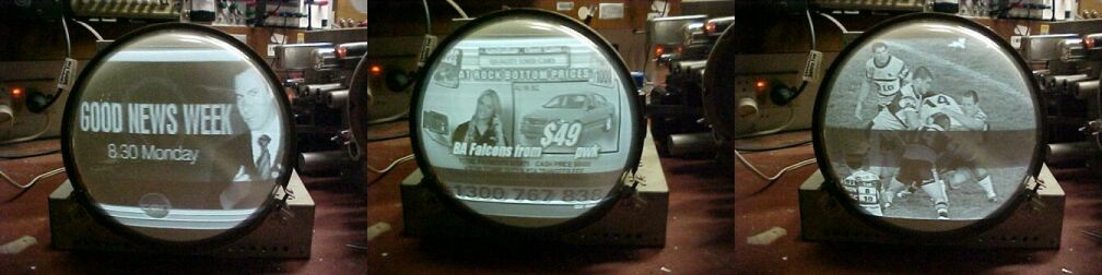
Some off air pictures. The 7JP4 was in good condition. Ignore the
dark band; it's caused by my camera having a too fast shutter speed.
In due course, I discovered that later production used a different linearity correction circuit, which suggests the problems I encountered had been experienced before. However, with good linearity obtained with my modification, I did not try the later version.
Sync Separator Problems.
The picture chassis was now finished,
and I could attend more closely to the RF chassis with its sync and tuner
problems. Sync was poor. Scene content was obviously present in the sync,
which was observable on the CRO. At medium to low contrast settings there
was a severe 50c/s ripple on the sync pulses. This wasn't present in the
video coming out of the 6AL5, so had to be associated with the 6AU6 video
amplifier. Increasing the filtering of the B+ feeding the 6AU6 reduced
it considerably. Again I had to do a mod, and permanently connect a 10uF
across the existing 10uF filter condenser that feeds the 6AU6 video amplifier
and the front end of the set. This, despite the fact the existing 10uF
electrolytic tested good, indicated inadequate filtering. True, it would
have been better with the set running off 60c/s mains so I felt justified
adding the extra capacitor, but shows the filtering was at its limit to
start with. For good measure I added an extra 22uF across the 20uF connected
to the filter choke. Now, the sync was good on the test pattern. However,
once I went back to off air signals it wasn't much better, with video content
still contaminating the sync pulses. I played around with the bias of the
6AU6 sync separator but this didn't achieve much. Visions of installing
an LM1881 IC came into my head, but that would be too drastic a modification.
Surely with such a simple circuit there couldn't be much wrong. I had noticed
an extra resistor on the circuit diagram not present in my set. It's the
270R between the 6AU6 cathode and the other cathode bias components. I
had no idea why it was there and was sceptical of it being required. After
all, with less than 1mA of plate current, 270R isn't going to do much.
But I tried it anyway, and that was it! One would assume it works because
there's no bypass capacitor across it and thus allows some AC feedback
to stabilise the circuit. Or it could be the suppressor grid needs to be
slightly more negative than the cathode. Interestingly, this resistor is
not present in later production.
There was still the occasional loss of
vertical sync on scene changes and a little bit of horizontal instability
on strong channels if the contrast is wound up too high, but it would probably
have been acceptable in 1949 in a cheap portable set.
A later trawl through my early 50's electronics
magazines (Radio News or Radio Electronics) had an article on the Pilot
TV37. Much to my interest, this set uses the same 6AU6 sync separator/DC
restorer as the Sentinel. Pilot also included the mystery 270R resistor,
but their cathode bypass is only 5uF. I wonder if the shorter time constant
would get rid of the corrupted sync on some scene changes.
Under the RF chassis. The 130V selenium rectifier is at the bottom.
By 1948, prefabricated tuners had been developed and the Sarkes-Tarzian
unit used here is such an example.
The Tuner.
Now for the tuner. I'd found my initial
attempts at adjusting this to be way out; I'd been using one channel higher
than I should have. Once I learned what each oscillator slug corresponded
to what channel, I could set about this in a more methodical way. It turned
out that C11 was way out, allowing the local oscillator to run about 6Mc/s
higher on all channels. C11 is adjusted by a screwing a slug in and out.
In the version of this tuner that has user adjustable fine tuning, this
capacitor would perform that function. Instead of being slug adjustable
I would presume it would be spring loaded, bearing against a cam attached
to the fine tuning control.
Incidentally, one can see the screw hole
for where the Ch1 oscillator screw would have been. The rotary switch certainly
allows for Ch1 too. Not surprising as this was not long after Ch1 had been
dropped in the U.S. In fact, the Hallicrafters T54 still had the Ch1 position
on its push button tuner.
Despite the resistance coupled RF amplifier,
it does contribute to the gain. Some channels can be received with no aerial,
80km from the transmitters. However, in comparison to a more modern set
with a cascode RF amplifier, it is less sensitive. The Radio Electronics
review made a point of this, mentioning Sentinel claiming an indoor aerial
to be useful only in optimum conditions.
Tuning for Australian channels.
Back to the tuner. Unfortunately, some
of the Australian channels are halfway between the American ones, and this
can really test the limit of adjustment with some tuners. Luckily, although
this tuner is of the incremental variety, as far as the RF circuits go,
each oscillator coil is separate and functions on its own. This eliminates
the problem where a single tapped oscillator coil is used, and adjusting
one channel throws the rest out of alignment.
Brass screws are used to adjust the local
oscillator frequency. Where brass is used, screwing the core in raises
the frequency, whereas ferrite lowers it.
For the receivable VHF channels in the
Blue Mountains, channels 2,3,7,9 and 10, I used the corresponding American
channels 3, 6,8,10 and 12.
Australian channels 0, 4, 5 and 5A are
outside the U.S VHF TV band so are not receivable. Although 5A (Newcastle)
is receivable here, I do not rely on it as it's merely a translator for
Sydney Ch2. Channel 3, also from Newcastle is not worth watching as it's
largely rebroadcasting Sydney's Ch9 which serves up American sitcoms and
sport; both of which are a waste of transmitter power.
For Ch2, either American channel 3 is tuned
up 3Mc/s or channel 4 is tuned down 3Mc/s.
For Ch3, American channel 6 is tuned up
3Mc/s.
For Ch7, American channel 8 is tuned up
1Mc/s.
For Ch9, American channel 10 is tuned
down 3Mc/s or channel 11 is tuned up 4Mc/s.
For Ch10, American channel 12 is tuned
up 4Mc/s or channel 13 is tuned down 2Mc/s.
Whether you tune up or down to get the
channels depends on the range of adjustment. It is also preferable from
the RF tracking point of view to use channels that require least adjustment.
Needless to say, channel 7 works the best. Modern solid state sets
with a varicap tuner do not suffer this limitation of course, and will
get all the capital city VHF channels with no modification.
Lastly, the set was reassembled in its
cabinet and the picture tube rotated to the correct position. Not an easy
operation to do it in situ with the set on, but my nimble fingers are used
to doing things like that. Getting at the tube clamp that goes around the
front of the CRT requires some dexterity. The other option of trial and
error removing the chassis, rotating the tube, replacing it and seeing
if it lines up seemed too tedious.
Final job was to fix the channel knob.
I put a 9BA bolt through the knob so it matched up with the gap in the
tuner shaft. No way can it slip on the shaft now.
My first commercially made electrostatic set is now up and running.
Summary.
The cheap '"let's see what we can get
away with" factor is evident in this set. The poor vertical linearity may
have escaped the non technical purchaser of this set, but the way the sync
separator was, that could not be ignored. Maybe the original 6AU6 sync
valve just so happened to have the right characteristics, and the set did
work ok when new. But if this was so, having a design that only works with
selected valves is poor practice.
In any case, the sync separator was still
not perfect after the modification.
The low RF gain I ended up with on Ch10
is admittedly my fault as I've forced the tuner to work 4Mc/s off frequency
without having attended to the associated RF circuits. I would have preferred
to use U.S Ch13 instead of 12 but there wasn't enough downward frequency
adjustment.
Sound quality is actually very good. The
video IF overloads on very strong signals which is hardly surprising given
the simple AGC cannot throttle back the video IF gain enough. However,
I do have strong signals from my aerial system, and it isn't difficult
to attenuate the signals if overload is evident. This is one limitation
of simple AGC. However, it is important to remember that when this set
was designed, AGC of any sort was new to the TV scene, as was intercarrier
sound. The design of sync separation and electrostatic deflection circuits
had been established since the mid 1930's, so I do feel the set should
have performed better in these areas.
To sum up, the things which needed attention
before this set was put into production are: 1) improved vertical linearity,
2) vertical blanking circuit required, 3) sync separator made immune to
scene changes, 3) something better than a fluted shaft for the channel
knob that can take the stress of turning the tight tuner shaft.
Performance is not as good as the Admiral
17T1, or my homemade 5BP1 set. However, it is a usable set despite the
limitations, and I'm fortunate to own this piece of television history.
Postscript.
With the end of analog TV transmissions
in Australia as of December 2013, retuning the sound IF stages and tuners
of system M television sets is a pointless excercise. It's less work, and
in many cases the results will be better, to simply use an RF modulator
for system M fed with the local 625 line 50 field video signal from a digital
box, DVD player, etc. In effect, the set is fed with a system N signal
(625 line 50 field but with 4.5Mc/s SIF and U.S. channel frequencies).
Low cost VHF modulators for system M can be easily obtained from the U.S.
eBay. It is of course possible to modify a system B modulator instead.
The Airline 7" Revisited in 2021.
By 2021 I had decided to restore this
set back to its original 4.5Mc/s sound IF, and retune all the channels
back to their orignal frequencies. Several things had encouraged this decision.
Firstly, analog TV had been off the air for eight years, Secondly, an inexpensive
broadcast quality modulator covering all U.S. channels had become available
on eBay, and finally, there would be an improvement in performance.
While merely retuning the sound IF will
allow a TV of U.S. standards to work off air in Australia, there is more
to it than that. It must be remembered that the U.S. standard has a 6Mc/s
channel bandwidth. This is narrower than that of the Australian standard
with a 7Mc/s channel bandwidth. As such, the alignment curve of the U.S.
set means that the response will be well down at 5.5Mc/s, and depending
on the set, the sound signal may be noticeably weaker. The correct thing
to do would be to realign the video IF to compensate, but since this is
a lot of work, and the results are passable without realignment, it's easier
just to retune the sound IF and leave it at that.
The next thing is the channel frequencies.
In most instances, the Australian channels require that the tuner's local
oscillator be shifted by 3Mc/s on some channels. However, unless the RF
circuits are also retuned, the overall response is affected. Again, it
usually works well enough without doing that, and the easy way out is taken
instead.
Now that off air analog signals are no
more, it seemed pointless to keep the set tuned to frequencies it would
never need again. By using a U.S. standard modulator, the sound IF could
be restored with an improvement in sound quality, and similarly, with the
tuner operating on the frequencies it was designed for, the video response,
and resulting picture quality should also be improved.
The modulator I chose is an unbranded type with the model designation M69. It is available in two basic versions; one that works on U.S. and European channels, with selectable sound IF, and the other is a 'dumbed down' model for Australia, which does not have any configuration settings available. For this version, the sound IF is fixed to 5.5Mc/s, and the channels are Australian only. It is a very good modulator that not only outputs a very strong signal (usable as a low power transmitter in itself), but does not have the problem of many cheaper units, where peak whites in the video signal cause excessive modulation and frame buzz. Of course, the U.S. version requires 120V. There is also a European version which appears to be the same modulator, but for 230V. The Australian version, depsite only operating with Australian channels, comes fitted with a European plug but an adaptor was supplied.
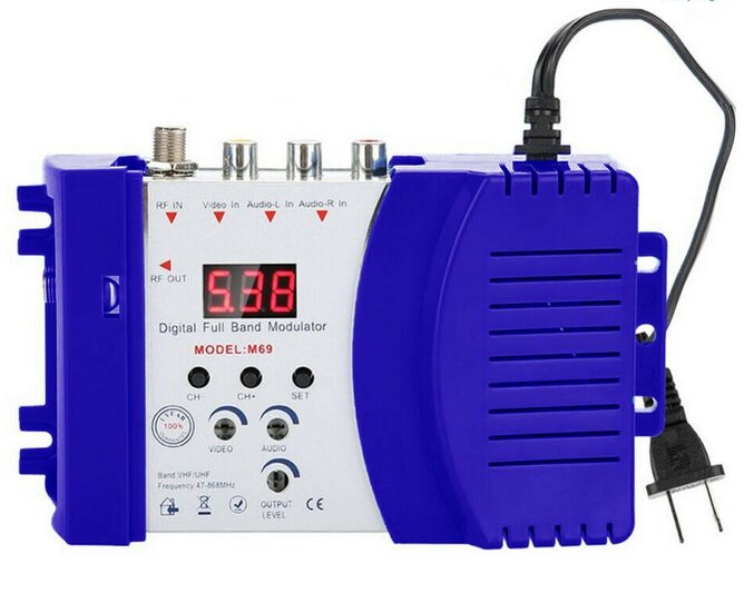
M69 Modulator is very versatile with high output, and gives a broadcast
quality signal. Get the U.S. version if you need all the features.
I ordered the U.S. version to use with the Airline, and my other U.S. standard TV sets. It's a very versatile unit, and since it can also be configured for European standards, it means it's suited to Australian sets where the channels are the same.
Both chassis set up side by side for service access.
In the intervening years, the 400-TV had
had some mention on various internet forums. I was surprised at some of
the comments. Some commented that 7JP4's were usually weak giving a dim
picture. Maybe I've been lucky, because both examples I've seen; one being
in this set, and also a 7" Admiral 17T1 I restored for an acquaintance,
have been good with a picture viewable with normal room lighting. I do
wonder if a lot of picture tubes get blamed because of other circuit faults.
In particular most restorers are aware of capacitor replacement, but seem
to overlook resistors drifting high. Another interesting discussion was
the use of ceramic capacitors to couple the deflection plates. Apparently,
there is some property whereby the capacitance of a ceramic capacitor changes
with applied voltage.
This is meant to cause strange effects
when they're used as coupling capacitors for the deflection plates. Again,
I've not had any problems with this. The general thoughts towards 7" electrostatic
sets were that they were cheap junk, incapable of good performance.
On a positive note, that should keep the
price down for people like me who do understand them, and know how to restore
them. Another strange comment was that electrostatic tubes soon go dark
because they have no ion trap, and as such the phosphor gets burned. Actually,
electrostatically deflected tubes don't need an ion trap, because the ions
are deflected with the electrons. With magnetic deflection, the ions are
not deflected to any degree, so they are concentrated in a beam, which
being inline from the cathode, ends up in the middle of the screen burning
it.
Retuning the Tuner.
Starting at U.S. channel 13, I went through
each channel adjusting the brass screw slug for optimum results. Due to
the separate oscillator coil for each channel, I found that once all the
channels were set, adjustment was still good when I went back and checked
them all again. Notably, the picture quality was consistent across all
channels.
Sound IF.
Initially, to get the sound channel working
on 5.5Mc/s, the tuning capacitor had to be removed from the sound IF coil,
along with a few turns of the winding. Also, the ratio detector transformer
required that the primary capacitor be changed from 12pF to 6.8pF, and
the secondary capacitor from 82pF to 39pF. Restoring it back to 4.5Mc/s
simply entailed replacing the original tuning capacitors and retuning everything.
Fortunately, there was enough adjustment in the sound IF coil not to have
to replace the turns of wire I'd removed.
The result was a noticeable increase in
volume once it was back on 4.5Mc/s.
I also took the opportunity to replace
the remaining paper condensers in the audio section. All of them did test
leaky, and while they didn't actually affect performance, it's obvious
they will only get worse. The 10uF cathode bypass for the 6AS5 was also
found to be open circuit and was replaced. All the remaining original electrolytics
were checked with an in circuit ESR meter and found to be good.
Sync Improvement.
In my initial restoration, I mentioned
problems with the sync separator, and modifications to improve it. While
these helped immensely, I was still not completely happy with it. There
was still some evidence of the video signal in the sync pulses.
One of the production changes to the set
design was the AGC filter capacitor. Initially, it was .25uF, but later
1uF. I had an idea that there might be tilt in the video black level, seeing
as my set had the smaller capacitor.
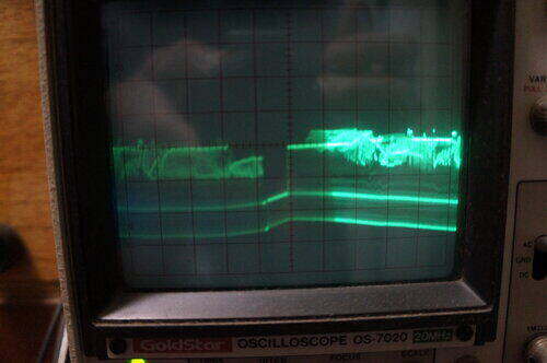
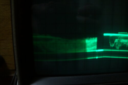
Black level tilt with 0.22uF AGC filter at left, and 1uF at right.
Tilt is most evident in the vertical blanking interval.
Indeed, there was noticeable tilt which wouldn't be a good thing for sync pulses. Increasing the filter to 1uF fixed this, and made the picture much more stable.
Some of the resistors in the picture tube chassis had since drifted and were replaced. These were the 4.7M plate resistors,for the 6SL7, and their series 470k, and also the 47R in series with the B+ to the EHT oscillator. By now, the picture was very good.
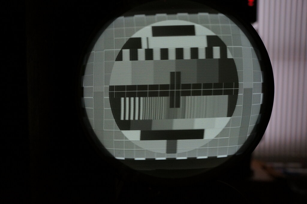
Philips PM5544 test pattern comes up very nicely on this 7JP4.
Power Supply.
Some wax had dripped from the filter choke
since my initial restoration. This shouldn't be, given the not very high
current drawn, and I suspected it was because I had bypassed the selenium
rectifiers in the doubler circuit with silicon diodes. The B+ was actually
higher than it should be.
Just to check again, with only the selenium
rectifiers in circuit, the B+ was about 30V down from what it should be.
One of the rectifiers was running too hot to touch. Obviously, the silicon
diodes had to stay. Normally, a resistor of 22R is about right in series
with a silicon diode, when a selenium rectifier is being replaced. Rather
than provide two separate resistors, I replaced the 10R surge resistor
with a 30R 10W type. As it was, the original 10R resistor was in poor condition
with the phenolic former charred in half. B+ was much better now, with
277V at the filter choke input. Filtered B+ was now 261V. (With the silicon
diodes and original 10R, the B+ was 20V higher than it should be). For
the selenium rectifier used for the RF chassis, there was no need to increase
the 33R surge resistor, since the B+ was 143V at the first filter.
Fuse.
Later versions of this set had a 250mA
fuse in series with the filter choke on the picture tube chassis. Since
mine is the early version, there was no fusing at all. I wasn't keen on
this aspect of design, especially now that the rectifiers were all silicon
types. When these fail, they always short out. While the 33R surge resistor
in the front end chassis should burn up if there's a short, on the picture
tube chassis the surge resistor will take a lot longer, and can't be counted
on to work properly as a fuse. Glowing red hot next to the wooden cabinet
is not a good situation!
I considered adding the 250mA fuse as
per the later version, but a limitation of where it is connected means
that it won't protect against one of the rectifiers being shorted - the
one between the input capacitor and earth. A better place to put it is
in series with the surge resistor, so that everything is protected in the
event of a B+ short or a diode breaking down.
The best place for the fuse is in series
with the transformer primary, since the windings are then protected, and
also the heater circuit. I installed a 2A fuse in an in-line fuse holder
in series with the power switch.
Set back together.
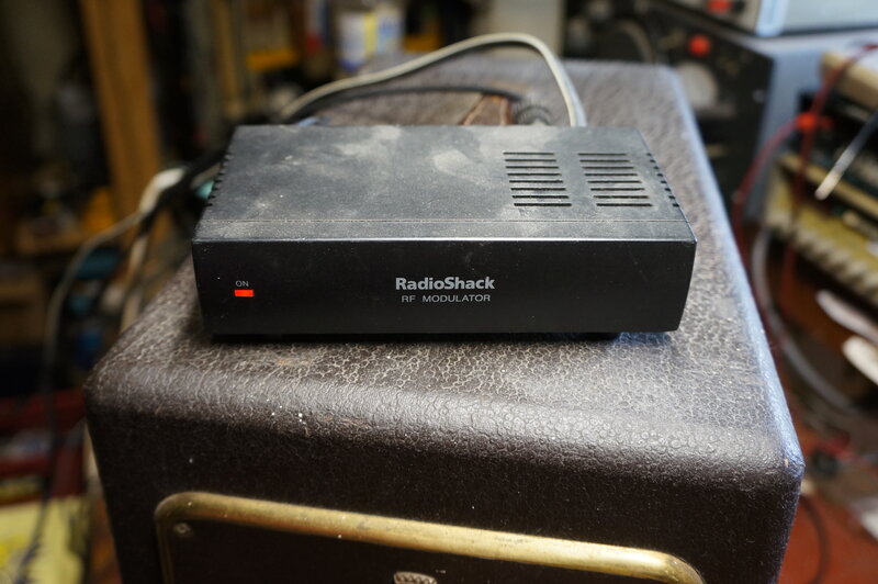
Set will now be used with this Radio Shack modulator which outputs
on channel 3 or 4.
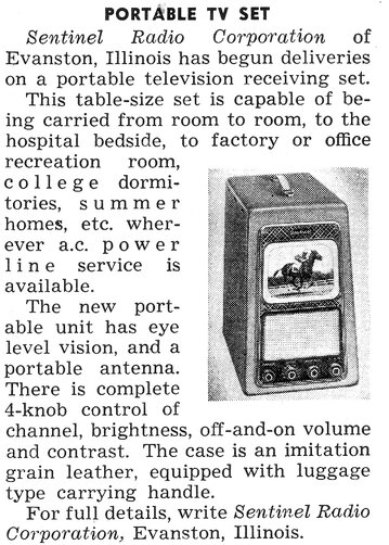
From Radio News, November 1948.