Despite the apparent simplicity of the final design, there were a number of difficult challenges to overcome.
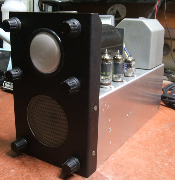
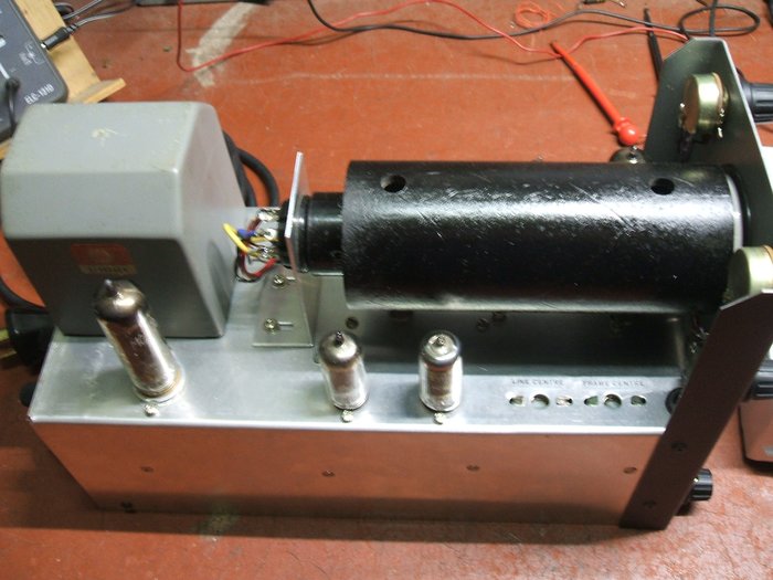
From left to right, top to bottom, controls are: Focus, Brightness, Line Hold, Frame Hold, On/Off Volume, Contrast.
This project came about mainly as a result
of collecting a quantity of 902 CRT's over the years. Added to that, I
have a particular fondness for electrostatically deflected TV sets.
Despite the apparent simplicity of the
final design, there were a number of difficult challenges to overcome.
From left to right, top to bottom, controls are: Focus, Brightness,
Line Hold, Frame Hold, On/Off Volume, Contrast.
Background.
With the cessation of analog TV transmissions
in December 2013, it was considered pointless to include an RF front end
in the design. Instead, the audio and video signals from a DVB-T receiver
would drive the unit. In this regard, it is probably more correct to call
it a video monitor, although with the digital receiver it is still a complete
off air receiving unit.
Only for sentimental reasons or for reproducing
an old design, is it worth making up a tuner and IF strip because this
will necessitate a modulated RF output from the signal source anyway. As
I was not aiming to recreate a vintage piece of circuitry, there was no
question in omitting it.
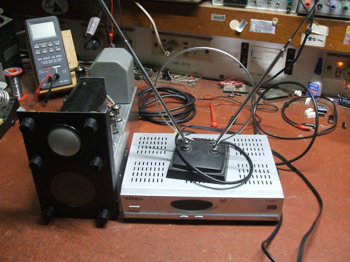
Signals are provided by a DVB-T receiver. Of course, a VCR, DVD
player, camera, or any other video source can be used.
The 902 (or 902-P1) cathode ray tube was released in 1938 by RCA, intended for low cost oscilloscopes, and a few American magazines of the era describe homemade TV receivers using this tube. It is octal based with a 2" green screen of medium persistance (P1 type phosphor). These TV designs used simple thyratron timebases, driving the deflection plates via a single stage amplifier. The RF front end was simple with a mixer/oscillator circuit feeding a couple of stages of IF amplification. With the highest TV channel not more than about 60Mc/s, octal valves of the time worked satisfactorily in strong signal areas.
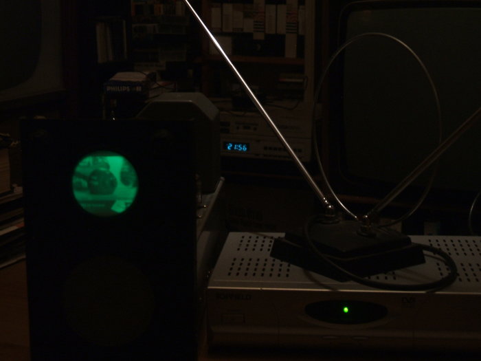
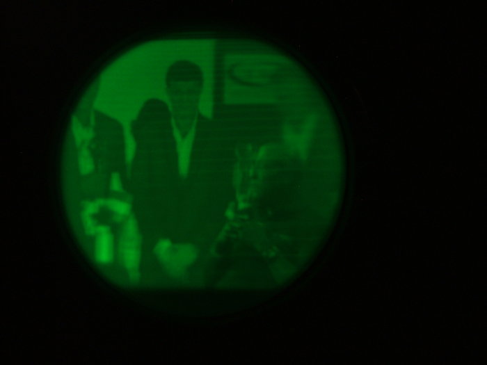
Off air reception on the 2" TV receiver.
My design.
Having built the Radio Television &
Hobbies 5" TV receiver using a 5BP1 tube back in 1984, electrostatic sets
are no stranger to me. I also have a commercially made example, a Sentinel
400TV
Initial thoughts were for a two stage
pentode video amplifier (required to preserve video polarity as the 902
is grid modulated), a single pentode sync separator, thyratron timebases
and triode or pentode output stages, depending on gain required. Audio
would use a simple triode/pentode arrangement. Physically, the chassis
would be as compact as possible. Modern valves would be used simply because
I don't have enough 2.5V heater 6 pin base valves to use for new projects
(or the power transformer required).
I had a CRT demonstration unit, made up
many years ago by a staff member at my work, which conveniently used a
902 CRT. This simply applies the correct voltages to the tube and allows
one to demonstrate the shift, focus, and brightness controls. This allowed
me to familiarise myself with the voltages required to drive the tube,
and to get an idea of brightness and focus.
For the thyratrons, I tried 2D21's. These
are a modern industrial 7 pin pentode type and I have a good quantity of
them. Results were not particularly good, but as they weren't designed
for timebase use this is not surprising. The problem was jitter with the
50c/s frame oscillator, and I could not get good oscillation at 15,625c/s
for the line timebase. Type 884 would be better, being designed for timebase
use. Regardless of type used is the non linear sawtooth which would require
correction for an acceptable TV picture. Then there was having to provide
for 600mA heater current for each 2D21. With these disadvantages, I changed
the design to use Miller-Transitron oscillators. This would simplify the
timebase design, providing a perfectly linear scan, and possibly drive
the CRT plates directly. Experiments seemed to confirm the output voltage
was high enough to do this.
Now that I knew what valves were required,
a chassis was designed, punched, and bent up. Given the small power transformer,
considerable thought was given to minimising heater current and this determined
the valve types used.
Here, I used 6BH6's where possible. These
are roughly similar to a 6AU6 but with half the heater current, at 150mA.
A similar low current heater type is the European 6CQ6/EF92. The video
output would use a 6AK6, again a 150mA heater type, similar to the European
6AM5/EL91. For the audio, a 6AB8/ECL80 was chosen.
The set would be constructed on an aluminium chassis with a black Marvi-Plate front panel. The CRT was to be supported at the front simply by it resting in a hole in the front panel lined with plastic edging strip. So that the tube could be rotated, an Amphenol type octal socket with spring clip was used at the other end.
The fun begins...
The initial timebase and sync circuits
were based on designs appearing in Practical Television during the 1950's,
when electrostatic TV sets made from disposals components were very popular.
With a theoretical circuit drawn up, the set was wired thus. With the compact
design, I used tagboards as well as tagstrips for the component mounting.
Upon first powering up, things were not always what they should be. This
is not surprising, but to solve all the problems took more work than expected.
At this point it is best to show the final
circuit and explain each of the stages and their development.
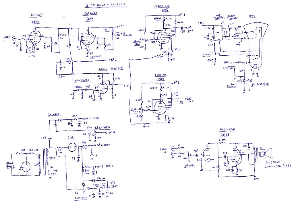
Final circuit of the 2" Television. Note there
is a mistake - pins 4 and 6 on the 902 connections need to be swapped
otherwise the picture will be reversed. The 220K 6AK5 plate resistor can
be taken to the 350V supply for increased output and better locking of
the line oscillator. Improvement in contrast control range can be obtained
by connecting a 470 ohm resistor in series with the contrast pot, or alternatively
using a 2K or 2.5K pot.
The 902 Cathode Ray Tube.
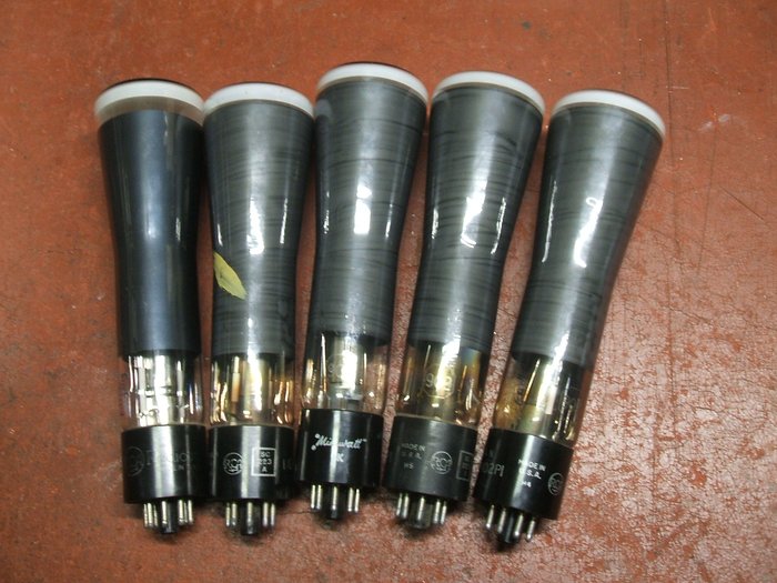
My 902-P1 tubes were looking for a use...
A limitation of this tube is the common
connection between one of the X and Y deflection plates, presumably because
the octal base simply does not allow for separate connections. This means
the deflection has to be of single ended drive. I had heard of distortion
with tubes so driven, but apparently the small size allows one to get away
with it. In practice, the effects are minimal on the TV picture. There
is a small amount of trapezoidal distortion if one really looks for it.
The CRT was found to be very susceptible
to hum pick up from the transformer. In ordinary oscilloscope use this
would not be noticed, but the TV picture suffered defocussing and raster
distortion modulated by the magnetic field. Luckily I had supplied with
one of my 902's a shield made from steel pipe. This was mounted on the
chassis and solved the problem. Without the shield, the transformer would
have to be mounted remotely.
The application notes show the CRT operated
with negative EHT. This is standard with CRO circuits as it allows the
deflection plates to be at earth potential. However, this requires the
CRT's heater supply to be isolated. This along with extra complications
with video modulation means it is better to use the tube in a more conventional
manner.
One problem was very evident and that
was the picture would shift depending on brightness. I could not see a
logical explanation for this, and have certainly not had the effect with
other tubes. I can only put it down to the common plate connection. Indeed,
the voltage here was found to be varying with the beam current.
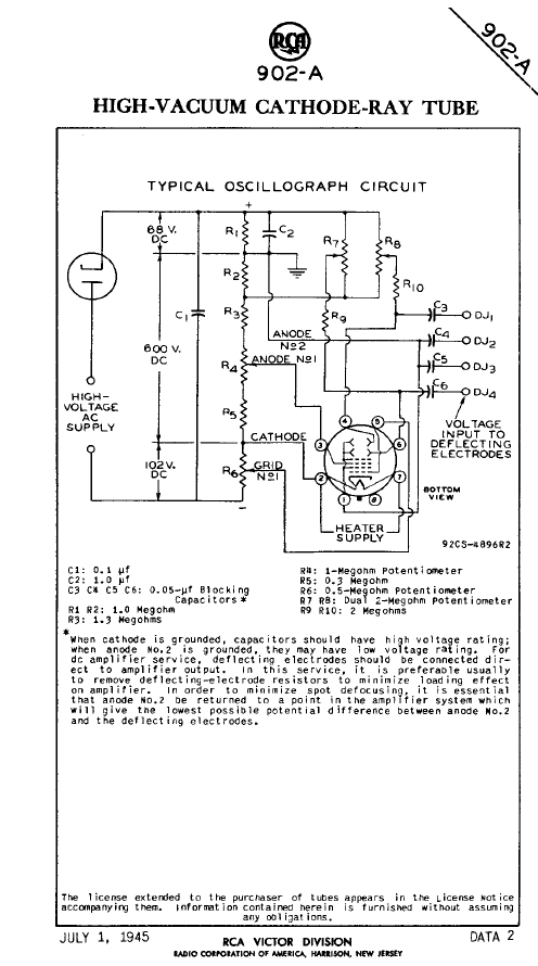
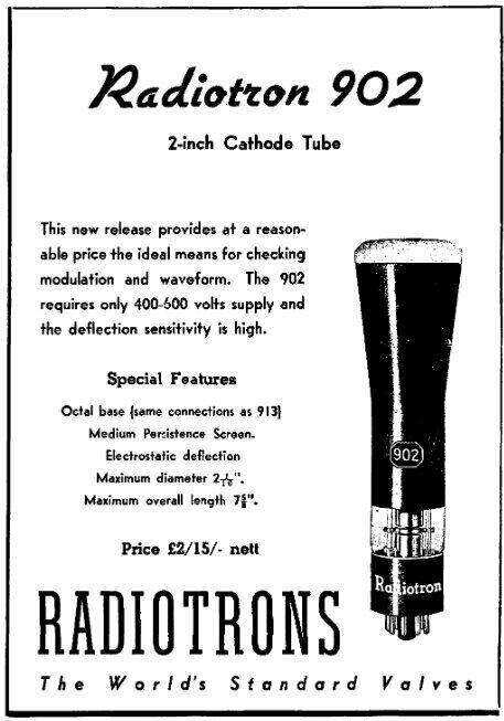
RCA's application data for the 902. At right is an advertisement
from AWA, announcing the Australian release in 1939.
The voltage divider I used to derive the
CRT potentials was based on the RCA design but modified for positive EHT.
However, with the final anode/common plate connection varying relative
to the other deflection plates it was obvious some kind of regulation was
required. Regulating the EHT did not fix the problem. Somewhat better results
were obtained by regulating the anode/common plate connection (pin 1).
Ultimately, I regulated the shift voltage relative to pin 1 by 75V zener
diodes. The plate voltages no longer shift relative to each other depending
on beam current, and the problem is fixed. The .22uF is required
for bypassing. Without it, the X and Y plates modulate each other through
the common connection resulting in a very peculiar distortion.
The focus and brightness controls are
conventional, but a DC restorer circuit has been included. It is necessary
to grid modulate the CRT because the cathode is common to the earthed heater
pin. Cathode modulation would require a low capacitance isolated heater
winding.
Video Amplifier.
This part of the circuit is straightforward
and presented no problems. Incoming video is terminated in 75R to present
the correct load to the signal source. Voltage here is 1V p-p.
Two stages are needed, because of the
incoming video polarity and that the CRT is grid modulated. I loosely based
the design on that used in the 5BP1 TV set. Both pentodes are operating
as ordinary RC amplifiers. Frequency compensation is provided to obtain
sufficient bandwidth. The 1000pF bypasses the 180R cathode resistor
for the 6BH6, thus increasing gain as the frequency rises. The 6AK6 stage
is compensated by including an 82uH choke in the plate load. As gain of
the stage increases with plate load resistance, we can see that as frequency
rises, so does the effective plate load. Measured bandwidth is about 2.5Mc/s
which is more than enough for the small screen size. Contrast control is
provided by varying the cathode degeneration of the output stage. It is
done here so the amplitude of video fed to the sync separator is always
at maximum amplitude, and to provide constant bias for the 6AK6.
Bias for the 6AK6 is grid leak, relying on the positive going sync pulses
to charge the .1uF coupling capacitor.
With no video signal, the plate and screen
resistors limit valve dissipation. 4.7uF capacitors bypass the screen grids
providing sufficient low frequency response. Drive to the CRT is around
30Vp-p. There is more than enough gain, and normally the contrast control
is operated at maximum resistance (lowest gain).
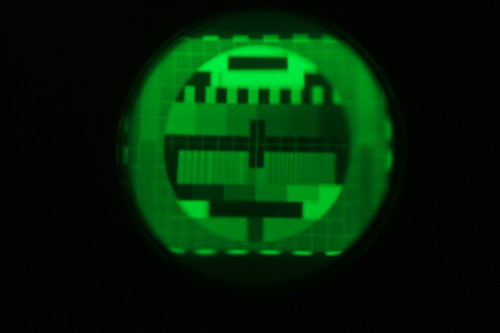
Philips PM5544 test pattern as displayed on the front of the 902-P1.
At right is the 6AK6 plate waveform with the test pattern displayed at
maximum contrast.
DC Restorer.
Most simple and/or low cost sets feed
the video to the CRT grid or cathode capacitively. This makes for a simpler
design because video amplifier operating conditions and signal strength
do not affect the brightness. Also, contrast and brightness controls operate
independently of each other. However, it will be noticed that the average
screen brightness remains the same, regardless of scene content. For example,
the screen is still lit up during a night scene.
I had seen mention of simple diode DC
restorer circuits many times in the past and had been intrigued by them.
Given the ease of incorporating one, I used the construction of this set
to try out the design. Results were obvious. With no DC restoration, and
a DC coupled CRO on the grid pin, the DC level fluctuated with scene content
as expected. With the DC restorer, it remained largely constant. The effectiveness
is even more obvious when the video signal is removed - the screen is virtually
blanked out.
At the plate of the 6AK6, the video signal
contains negative going sync pulses. The voltage across the .01uF charges
up to the sync pulse tips by means of the 1N914 diode.
This keeps the CRT grid at a constant
DC voltage. The brightness control merely offsets this voltage as required.
Of course, a valve could have been used, but with limitations on heater
current, the solid state diode was preferred.
Timebases.
Miller-Transistron timebases were only
popular in the UK and only then for a short period in the late 1940's-1950's.
This is surprising considering how simple and effective they are.
I had first used such a design in the
frame timebase of the 5BP1 TV set, so knew of its excellent linearity.
It is probably the only non thyratron
single valve timebase not requiring any inductive components. Oscillation
occurs because of positive feedback between the suppressor and screen grids.
The sawtooth component comes about because of the capacitor between plate
and control grid. The capacitor is effectively charged at a constant current
because of the amplification of the valve. Oscillation frequency is determined
by this capacitor and the grid resistors. Sync pulses need to be negative
going.
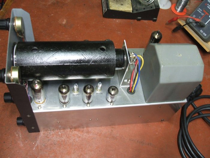
From left to right, the valves are 6AB8 (audio), 6BH6 (frame), 6BH6
(line) and 6AK5 (sync).
A lot of trouble was experienced trying
to get sufficient scan amplitude. While the screen, suppressor and plate
resistors all affect amplitude, it was found there simply wasn't enough
available to fully deflect the 902 even with all component values optimised.
Deflection senstivity of this tube is not very high, and having to use
single ended drive makes it harder.
I did try experimenting with adding triode
amplifer stages but without success. For one thing, linearity was ruined
and attempts at correcting it reduced the amplitude. It was becoming obvious
that the limiting factor was the amplitude was limited by the saturation
voltage of the valves. Attempts to 'force' a greater output simply resulted
in picture foldover where the sawtooth bottomed out. Obviously, 300V B+
was not enough. Raising this to 350V solved the problem, with full width
and proportionally high frame scan.
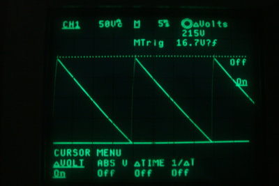
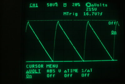
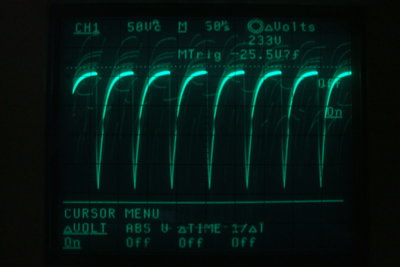
At left is the waveform for the frame oscillator plate, and at right
is the the line oscillator plate.
It might be wondered about the differences
between X and Y plate sensitivity. Indeed there is a difference because
of one set of plates being in front of the other and thus further from
the cathode. While it was actually possible to improve things by swapping
the line and frame plates, the end result was a reversed picture!
It should be pointed out here that the
Miller-Transistron circuit provides a negative going sawtooth - the opposite
to the positive going 'textbook' sawtooth. This is not problematic as long
as both timebases produce the reversed waveform, as the CRT is simply rotated
180 degrees for correct picture orientation.
Because of the common plate connection
in the 902, one has to use pin 6 for frame deflection, and pin 4 for line
deflection for the picture to appear the correct way up.
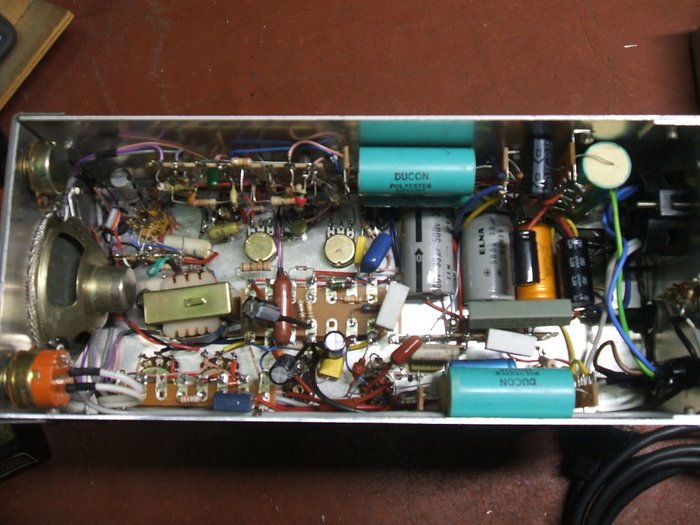
Under the chassis. Along the top is the timebase and 350V
supply circuits. Down the middle is the audio and video stages, and the
power supply. Along the bottom is the EHT circuit.
Sync Separator.
This was the most difficult and time consuming
section to design. The problem was worsened by the Miller-Transistron timebases
needing a high amplitude negative going sync pulse, and the low gain video
stages. In a commercially made set, the sync separator is usually fed from
the video output stage with about 60V p-p of video. This makes for easy
sync separation as the sync separator grid is driven hard into conduction.
Initially the circuit was a simple pentode
sync separator, based on early Practical Television designs. It was fed
from the plate of the 6BH6 video amplifier, but it was not driven hard
enough into conduction, with video still present in the output. This of
course caused locking dependent on the picture content. While a higher
gain video amplifier would have helped, it would have required valves using
more heater current. Using the 6AK6 to drive the sync sepator was experimented
with, but the problem here was the video polarity was incorrect. The sync
separator must have positive going sync pulses to charge the grid capacitor.
It's this capacitor charging current we want to drive the grid into conduction.
A limiting factor in all this was of course
having only one valve for the sync circuit. Having already built the chassis,
it would have been difficult to add another valve with little room to put
it. Any usable dual section valves require a 9 pin socket and due to the
location it was not practical to replace the 7 pin socket with one.
I then started experimenting with diode
sync separators. These had gone out of fashion in the 1940's, but the simplicity
was attractive. The concept of a diode sync separator is simple. If a video
waveform with positive going sync is fed into a diode via a capacitor,
the capacitor charges up to the peak voltage which is that of the sync
tips. Now, if a resistor is placed across the diode so as to discharge
the capacitor between sync pulses, then the capacitor will charge everytime
a sync pulse comes along. The diode charge current appears across the diode
load resistor and here the sync pulses are available.
The circuit is really a modified DC restorer
and by this means, the sync pulses are unaffected by the luminance component
of the signal.
It can be seen that this kind of sync
separator has no gain. If for example the incoming waveform is 1V p-p,
the sync will be 300mV peak at best. For this reason, I used a germanium
diode to keep voltage drop to a minimum. As with the picture tube's DC
restorer, a valve diode could have been used.
Results were good and at last clean sync
pulses were available, with the sync separator fed from the 6BH6. However,
being a fraction of a volt they are completely inadequate for triggering
the timebases. Here, the existing pentode was used simply as an amplfier,
conveniently inverting the pulses as well. Because of the repetitive waveform,
grid leak bias can be used, saving the usual cathode bias components. Initially,
a 6BH6 was used but even after optimising the screen and plate resistors,
gain was not really enough. How to increase this? Then I remembered the
6AK5, pin compatible in this circuit, and with similarly low heater power.
Sure enough, with a 6AK5 in circuit, gain was much higher and locking improved.
Further improvement was had by taking the 6AK5 plate resistor to the 350V
supply.
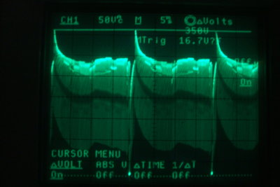
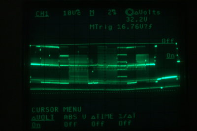
6AK5 plate waveforms. At left is at line rate, and at right is viewed
at frame rate.
At the 6AK5 plate are negative going line
and frame sync pulses. The frame pulses are integrated with a .22M and
470pF to remove the line sync. The resulant pulse triggers the frame oscillator
via a 2200pF connected to its suppressor grid. Line pulses are fed via
20pF to the suppressor of the line oscillator. It should be noted that
to look at the waveform it is necessary to remove the timebase valves.
This is because the suppressor grids of the Miller-Transistron oscillators
feed their own signal back out into the sync separator.
One problem noted was that the sync amplitude
required for good locking increases with increased amplitude of the timebases.
It was found locking was better when the timebases operated off 300V as
compared to 350V.
As well as this, ripple on the power supply
caused problems earlier on. With a ripple voltage amplitude not much different
to that of the sync pulses, it was not surprising to see the frame oscillator
trigger on the mains instead. Once this was attended to, frame locking
was quite good.
Audio amplifier.
I used a 6AB8/ECL80 because of the 300mA
heater current. This valve was not popular in Australia but it was used
in a few English designed TV sets sold here. An interesting characteristic
is the common cathode between triode and pentode sections. The triode section
is mounted above the pentode using the same cathode sleeve. Although the
grid bias specification is different for the triode and pentode sections,
with a simple audio amplifier like the one used here, the triode bias conditions
are non critical enough not to require a separate bias supply. Negative
feedback is provided by the 2.7M resistor between plates. The output transformer
is a 100V line transformer, Jaycar type MM-1900. Output power is 620mW
with frequency flat within 3dB from 290c/s to 8Kc/s. Because most signal
sources provide stereo, a resistive mixer is used prior to the volume control
to create a mono signal. Given the low impedance of most signal sources,
a 10K volume control was used. As an alternative to the 6AB8, I could have
used a 12AT7
as was done in the 5BP1 TV set. This also draws only 300mA heater current.
Power output and gain would be down, but still more than sufficient for
this application.
Power Supply.
The design of this was largely determined
by the AWA power transformer I had. It has a single 285V winding with no
centre tap, which meant half wave rectification was in order, if a valve
rectifier was to be used. It also has one 6.3V winding for the heaters.
The current ratings are unknown, but judging by the core size, I estimated
it would handle about 60VA. At a rough guess, heater current rating was
assumed to be around 2-2.5A. B+ would probably be 60mA or thereabouts.
As the B+ drain would not be particularly high, it was assumed there was
some leeway with regards to heater current. Power consumption of the set
turned out to be 47W, and the transformer does not run particularly hot
after several hours.
The 240V mains supply is also fed to a
three pin socket on the back of the chassis. One of the annoying things
about having to use digital boxes is that another power socket has to be
provided. Seeing as this set would always be used thus, it made sense to
include it on the set. The socket is switched by the same on/off switch
for the set itself. This means the digital box is only powered up when
the set is turned on. The power transformer primary is fused at 400mA,
and the mains socket at 3A. The socket is fused simply to protect the on/off
switch contacts in case of a shorted digital box, or someone does something
idiotic like plug in a radiator or washing machine.
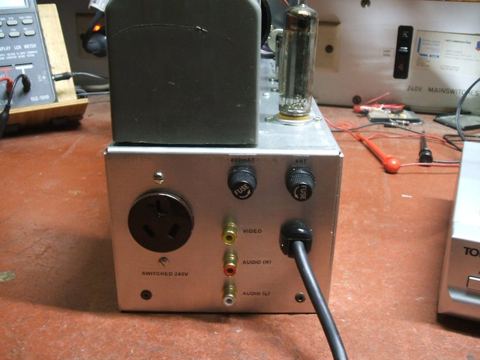
Back of set has a 240V socket for convenient powering of the DVB-T
receiver.
The 300V B+ supply comes from a 6N3/EY82
rectifier and an RC filter with two 33uF capacitors. Initially, the filter
resistor was only 470R and this resulted in about 4V p-p of ripple which
caused problems with the sync circuitry, as mentioned before. A 100uF as
the final filter improved this, and trying a filter choke instead of the
470R got the ripple to 1V p-p, and resonating the choke at 50c/s, was even
better. As it eventuated, the choke and higher filter capacitance were
not needed.
I had overlooked the fact the the 6N3
takes 900mA for the heater, thinking it was only 600mA, and should really
have used a 6X4 or 6V4 with the plates joined together instead. However,
transformer overheating has not been a problem, so the 6N3 stays.
The 6N3 rectifier is at the far left, with the 6AK6 and 6BH6 video
amplifiers to the right. Also visible are the preset centering controls.
The video amplifiers, sync separator, and
audio amplifier are fed from the 6N3 rectifier.
Various schemes for developing the 630V
EHT were dreamed up but the most sensible was a simple half wave voltage
doubler. Because of heater current availability and that floating heater
supplies would be needed, the idea of using valves was dropped. 1N4007
silicon diodes are used instead. The negative going current in the first
diode was used to advantage, providing the negative voltage for the brightness
circuit. Around -50V is produced here. The EHT is filtered with another
RC filter comprising of a 150K resistor and two .33uF capacitors.
As mentioned previously, it was found
necessary to provide 350V for the timebases. The cathode voltage of the
6N3 is not quite high enough, especially when some voltage has to be dropped
in the filtering circuit. One option was to increase the current available
from the 630V EHT supply and provide the 350V via a dropping resistor.
This was tried with some success, but the dropping resistor was wasting
about 7W. This was undesirable in the interests of minimising transformer
loading. The available EHT voltage was also reduced slightly.
Another option was simply to provide another
voltage doubler but for the timebases only. This worked well. To avoid
the problems of having to drop around 300V across a resistor, the doubler
circuit was designed to put out less than double the voltage when loaded.
This was easily done by selecting the input capacitor to suit; the reactance
of it limiting the current. A two stage filter was required to get the
ripple down to 1V p-p. One problem was that until the timebase valves had
warmed up, the filter capacitors would be exposed to excessive voltage.
On no load, over 500V was appearing across the 450V rated capacitors. A
zener diode clamp fixed this. Note the 75V zener between the 300V and 350V
supplies.
The 350V supply is prevented from going
75V above the 300V supply. When the set is first switched on and the valves
are not drawing current, the 300V supply is zero because the 6N3 has not
warmed up. Thus the 350V supply is clamped to 75V. As the 300V supply comes
up to full voltage, and the 350V supply drops, the zener diode no longer
conducts.
Performance.
Because of the small screen size, it's
more of a novelty than something to watch a two hour movie on. Having watched
television on a 5BP1 for many years, I find the green picture a non issue.
The picture really needs to be a minimum of 3" to be of long term entertainment
value, however.
Indeed, a lens placed in front of the
screen gives a marked improvement. Brightness is quite adequate for a normally
lit room, but it is important not to let light fall directly on the screen.
Focus is a slight problem given the age of the CRT's, as they are now slightly
gassy. Nevertheless, it improves with low brightness settings and is possible
to read some subtitles.
For what it is, the picture is remarkably
good and it makes a nice desk top TV. An enterprising constructor could
build it into a car dashboard, powered from the car electrical system and
using a 12V DVB-T receiver.
It is hard to imagine a simpler circuit
than the one presented here. None of the stages can be done away with,
except for the DC restorer. The audio stage could be simplified using a
single high gain pentode. While it couldn't be driven to full output, the
volume would still be enough for close viewing. While I have not tried
it, a single high gain pentode might work for the video amplifier, if the
video was fed into the cathode. Grounded grid operation would preserve
the video polarity. The input impedance in this configuration would probably
suit the 75R video source quite well. The power supply could be simplified
a little; one 350V supply for everything except the EHT. With the present
transformer, this would require a silicon bridge rectifier and choke filtering.
It is hard to imagine a simpler EHT supply unless a high voltage winding
was available, and even then only one capacitor would be eliminated.
Some of the controls could actually be
eliminated due to their non critical nature; the brightness, contrast,
height, and width controls could be replaced with fixed resistors.
Typical off air picture. Again, some quality is lost in taking the
photograph.
See the set operating at my YouTube site here.