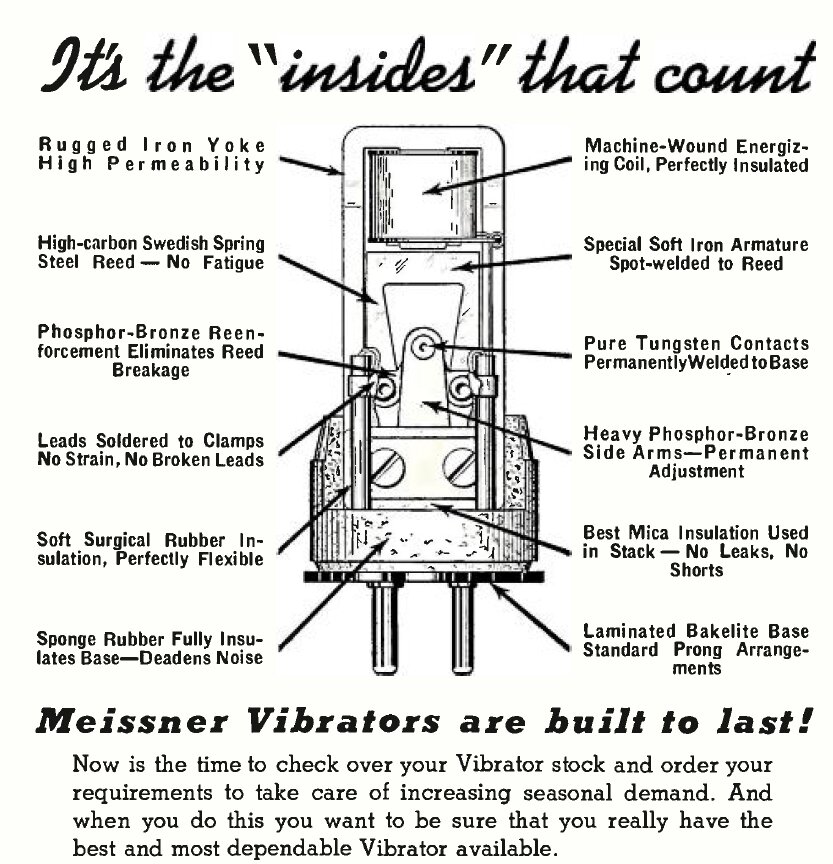
Meissner ad shows parts of a typical vibrator.
Meissner ad shows parts of a typical vibrator.
Construction.
There is much more to a reliable and long
lasting vibrator than the theoretical description so far given.
Remember, that for every thousand hours
of use, the reed flexes, and the contacts make and break around 360 million
times! For a mechanical device to achieve this without failure, or requiring
adjustment, is an impressive feat in its own right.
It should also be obvious by now that
the vibrator is no ordinary switch.
The Oak Vibrator.
This design was patented in 1934, and
remained largely unchanged until the end of manufacture (ca. 1973 in Australia).
Because of some of the unique aspects of its design, and being the most
common type Australian restorers are likely to encounter, a detailed description
will be given.
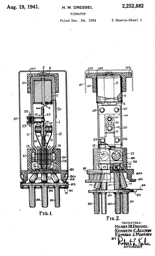
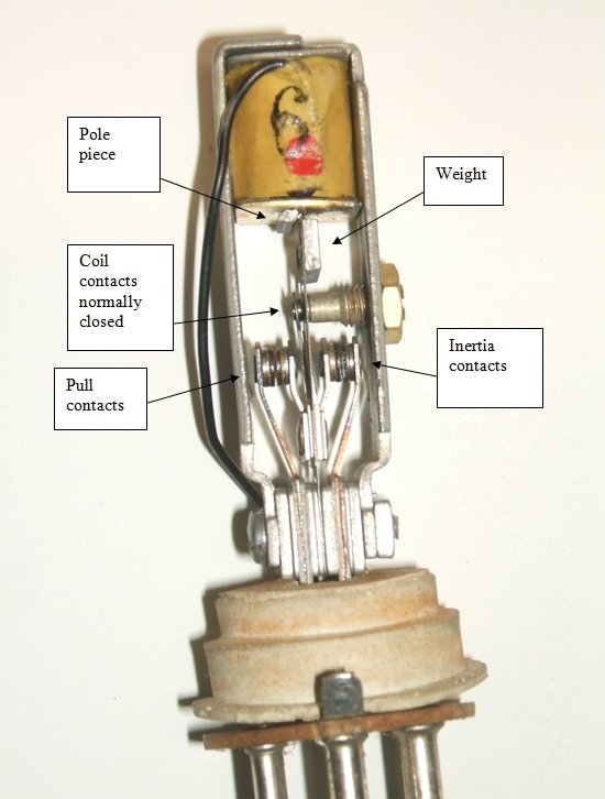
Patent and internal parts of Oak vibrator.
The separate drive contacts are of silver palladium, which eliminates the problem of tarnishing and non-starting. It is permissible to use precious metals here because of the low drive coil current. A special patented design prevents sparking and subsequent erosion of these contacts. Laboratory tests showed no deterioration of the drive contacts after 1500 hours.
It will be noted on many schematic diagrams depicting an Oak vibrator, there is a secondary winding on the driving coil which is short circuited. This is bifilar wound with chromoxide resistance wire. The purpose of this is to eliminate sparking at the drive contacts, by lowering the Q of the drive coil. This slows down the rate at which the magnetic flux collapses when the contact opens, reducing the back EMF. Other manufacturers of separate drive vibrators use more conventional spark suppression circuits with a resistor, a capacitor, or a combination of both, connected across the drive contacts.
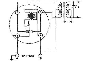
Note the short circuited drive coil secondary.
The reed is Swedish spring steel and the power contacts are made of Oakalite tungsten. The can is usually zinc, but some were aluminium. The vibrator mechanism is secured inside the can by a spring clip.
Vibrator Bases.
Most vibrators use a UX 4, 5, 6, or 7
pin valve base. A dual UX 6 base was used for some power vibrators. Octal
bases are uncommon outside military types. Delco (General Motors) developed
their own 3, 4, and 5 pin bases (the 4 and 5 pin types were used locally
by Ferrocart), and Mallory developed a 5 and 6 pin reversible base. Some
vibrators are wired in directly.
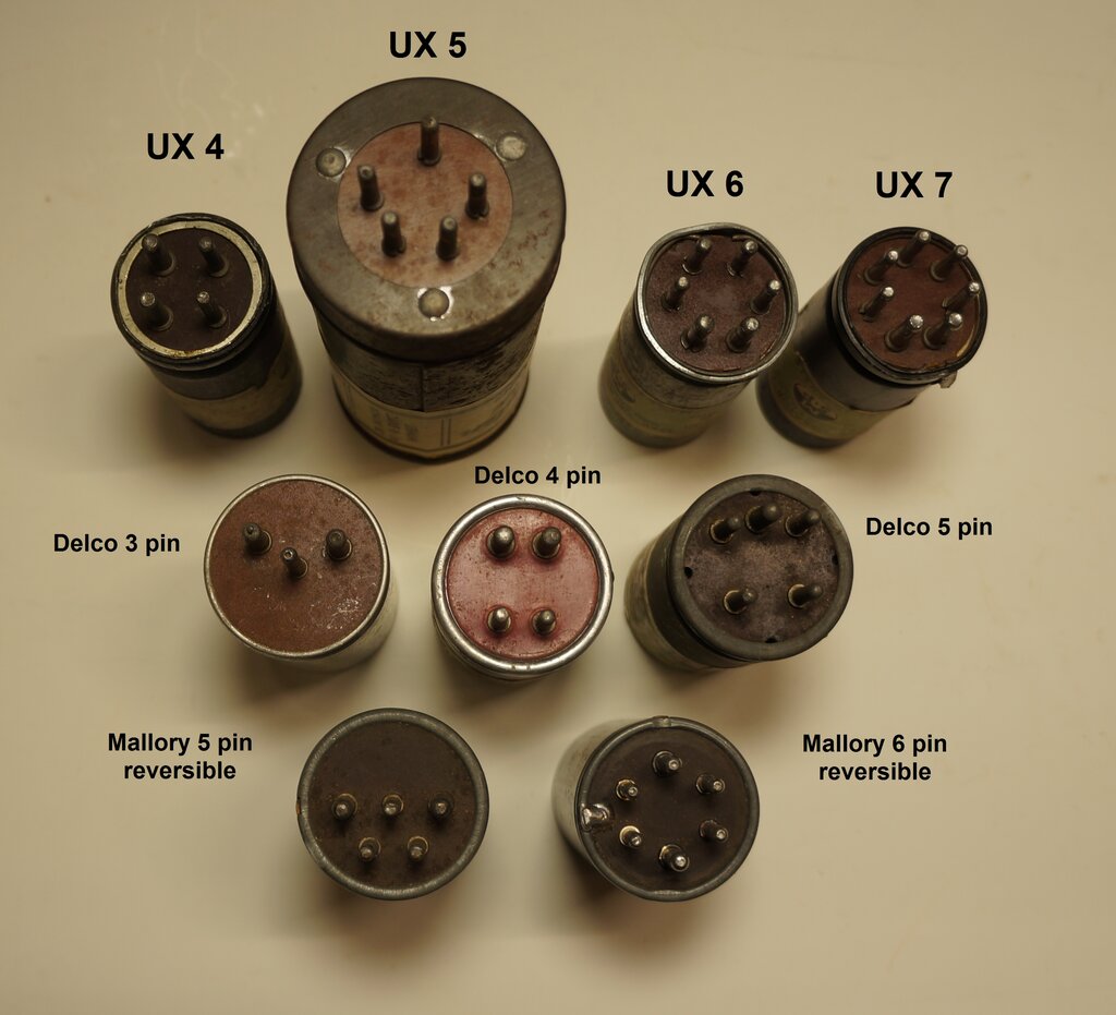
Common vibrator bases.
Timing circuits.
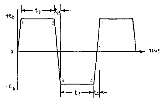
If a vibrator is fed into a centre tapped
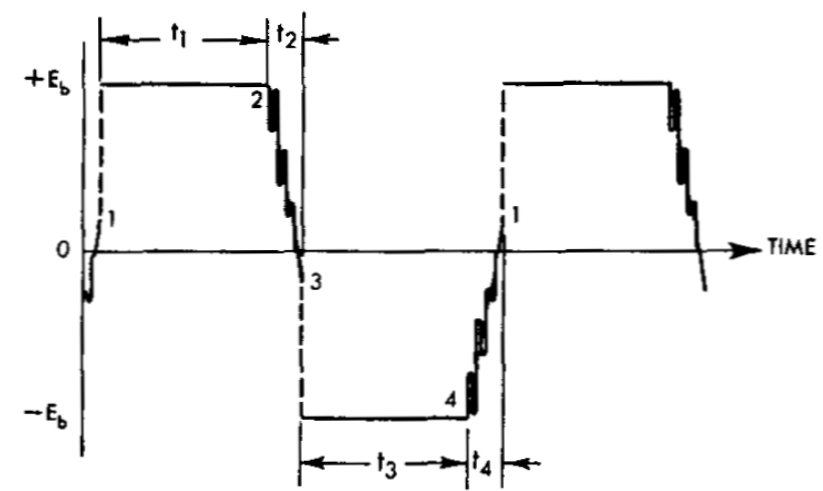
resistive load, the following waveform is produced:
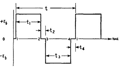
The pull contacts close at 1, and open
at 2. t1 represents the time when the pull contacts are closed. When they
open, there is no current flow (t2), until the inertia contacts close at
3. t3 represents the time when the inertia contacts are closed. Similarly,
when the inertia contacts open, at 4, current no longer flows at t4.
A resistive load can be used for testing
vibrators, because it gives a clear indication of contact timing and condition.
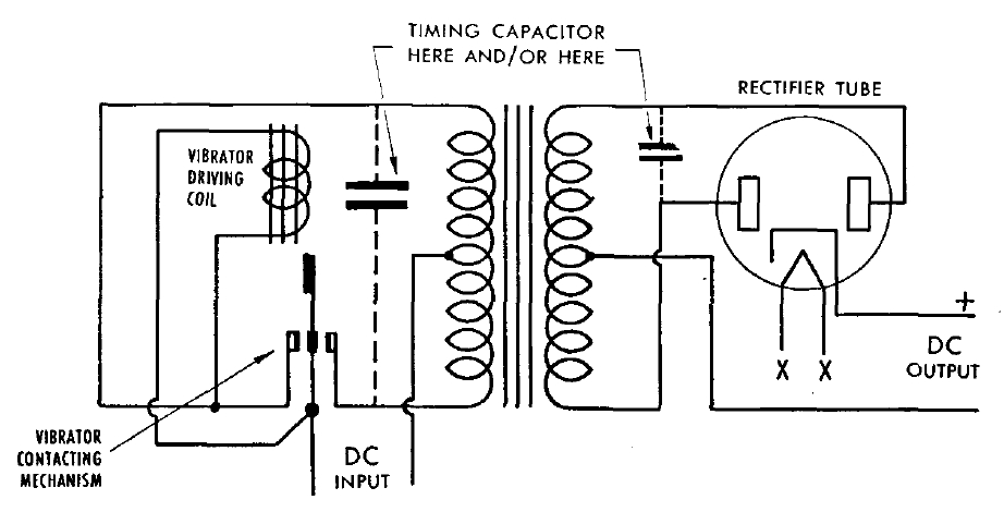
Operation differs when the resistive load
is replaced by a transformer.
Since a transformer is an inductive load,
high induced voltages would be generated at each make and break of the
contacts (t2 and t4). Apart from causing contact arcing, insulation failure
of the transformer could occur. To control these high voltages, a timing
or buffer capacitor is connected across the primary and/or secondary
of the transformer.
The capacitance forms a tuned circuit with
the transformer inductance, which is set into oscillation at each opening
of the contacts. By selecting an appropriate value of capacitor, this oscillation
reverses the voltage, so that it coincides with the voltage applied to
the transformer when the opposite contacts close.
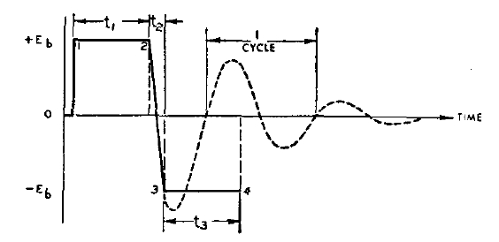
This is represented by the line from point 2 to 3. If the contacts did not close at point 3, the normal voltage decay curve would be represented by the dotted line.
With the appropriate capacitance connected
across a winding, the following waveform is obtained:
The vertical lines and discontinuities
now become a slope. This is the ideal waveform.
In simple terms, the timing circuit
controls the voltage waveform, so that the contacts make and break when
there is minimal voltage across them.
The greatest electrical wear of a switch
occurs when it is making and breaking current, not when it is actually
closed. If the circuit is arranged so that the current flows only after
the contacts make, and before they open, the contacts will subjected to
minimal electrical wear. The capacitor value must be carefully chosen to
ensure this voltage reversal occurs at the correct time. Many values of
capacitance will prevent visible sparking, but only one will provide this
correct operating condition. Understanding this was one of the breakthroughs
for reliable and long life vibrator design. In the early days, timing capacitors
(or buffer capacitors as they were originally called, since the timing
function was not properly understood) were selected by trial and error
and whatever stopped the sparking. Even though sparking might not be
visible, high peak currents may be present, and contact material transfer
can take place, causing contact pitting, and eventual locking.
Practical Considerations.
Ideally, the timing capacitor is connected
across the primary winding. However, the value of capacitance tends to
be in the tens of microfarads for a supply operating on 6 V. In the days
of paper capacitors this meant an impractically large capacitor. Electrolytic
types, while smaller, are unsuitable for continuous AC operation.
The way around the problem is to instead
place the capacitance across the secondary. The voltage step up of the
transformer also steps up the value of capacitance by the square of the
turns ratio, so a much smaller capacitor can be used.
To illustrate this, assume the timing capacitor
across the primary needs to be 20 uF.
The transformer has a 6 V primary and
250 V secondary. In practice this means a 12 V CT primary and 500 V CT
secondary, but the ratios are the same. Turns ratio is 41.7, and squared
is 1739. Now, by placing the capacitor across the secondary, it will be
1739 times smaller; which calculates to 0.012 uF.
However, now being connected across the
secondary, the capacitor has to be rated at a considerably higher voltage;
typically 1500 V when connected across a 500 V secondary. Nevertheless,
because of the low value, the capacitor remains of small physical size.
Sometimes the capacitor is placed across half the secondary, thus requiring
less of a voltage rating, and without requiring an excessively large capacitance
value (see the AWA 946-AZ car radio power supply shown in Part Two).
Because of transformer leakage inductance, the reflection of capacitance from the secondary to the primary is not perfect. Some power supplies, particularly operating from 12 V and above, therefore include a portion of timing capacitance across the primary. It becomes practical at higher input voltages; e.g. 12 or 32 V, to include more of the timing capacitance across the primary, since the capacitor value is reduced with an increase in supply voltage.
It is important to note that the value
of timing capacitance depends on both the transformer and vibrator characteristics;
in particular the operating frequency, the transformer inductance, and
the vibrator duty cycle. Substitutions of any one of these components should
not be made without checking the suitability of the others.
The best way to determine correct timing
capacity is by observation of the primary waveform. There are several waveforms
to know:
1) Ideal Timing Capacitance.
2) Practical Timing Capacitance.
3) Insufficient Timing Capacitance.
4) Excess Timing Capacitance.
Because a vibrator is a mechanical device,
it is subject to certain tolerances during manufacture, as well as a slight
increase in contact spacing as the vibrator ages. The timing capacitance
has to allow for this. Since the capacitance value is higher for a wider
contact spacing (i.e. a reduced duty cycle), the chosen timing capacitor
value is slightly higher than the ideal. In practice, it is selected to
obtain a 65% slope:
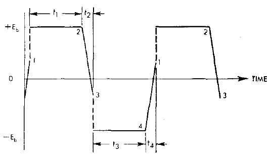
Practical waveform has 65% slope.
The capacitor is selected so the distance between points 2 and 3, and 4 and 1, is 65% of the total peak to peak voltage.
If the timing capacitance is insufficient,
the following waveform is obtained:
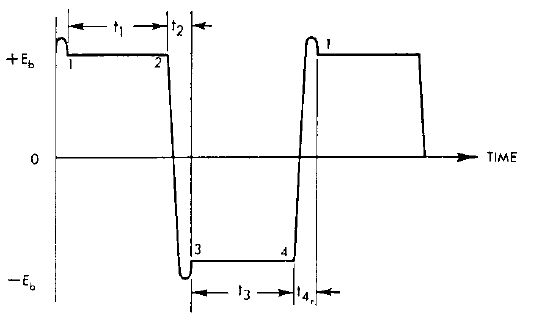
Insufficient timing capacitance.
It can be seen that the period of oscillation has reduced; i.e. increased in frequency. The peak of the first quarter cycle passes before the contacts close at 3. As such, high voltages are present, as shown by the overshoot.
If the capacitance is too high, the period
of oscillation is increased, and reduced in frequency:
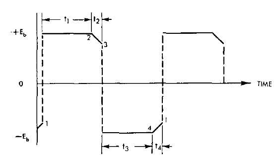
Excessive timing capacitance.
The period for voltage reversal is reduced
to much less than the needed amount.
This is undesirable because high peak
currents flow as the contacts begin to make, and causes contact material
transfer. This can eventually lock the contacts together. Furthermore,
the high transient currents create additional RFI.
A method which has sometimes been suggested for determining correct timing capacitance, is to measure the DC supply current of the power supply, operating into no load. The timing capacitance will be ideal when the current is at minimum. In practice, the change in current is very slight over a wide percentage change in capacitance at the minimum point, so the exact value can be difficult to determine. This method is not recommended unless a CRO is not available.
The waveforms described thus far are for
non-synchronous vibrators operating into no load; i.e., the rectifier is
removed. Synchronous types show a slightly different waveform:
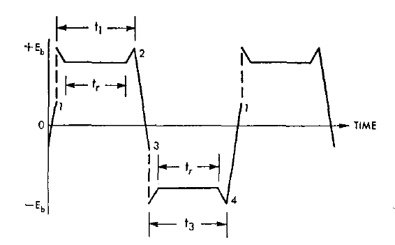
Synchronous waveform.
Unloaded, the synchronous waveform is the
same as for the non-synchronous, but when loaded, it appears as above.
The rectifier contact timing is shown by tr. The voltage drops for this
duration, because the B+ circuit is loading the transformer at this time.
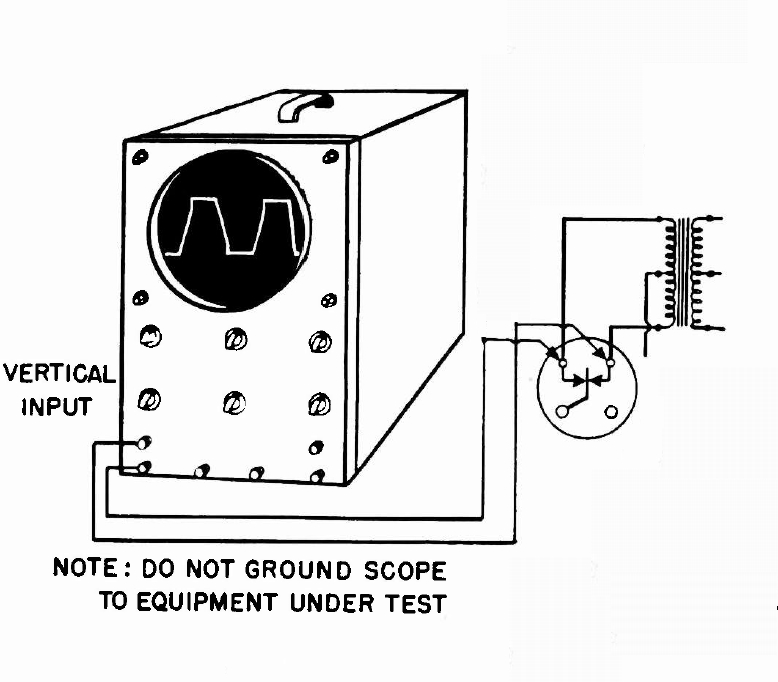
Observing the vibrator waveform.
The waveform should be measured across the full primary, since this is what the vibrator sees. It is important that the power supply for the vibrator must be isolated from earth for this measurement, since one side of the CRO input is earthed, which would otherwise cause a short circuit. The obvious exception is if the CRO is battery operated or otherwise isolated.
Resistors.
Resistors are often used in the primary
circuit, either connected across the primary winding, or across the vibrator
contacts. These reduce RFI by damping the voltage overshoot when the contacts
open. As such, they can also lengthen contact life. Values are typically
50 to 500 ohms, depending on supply voltage.
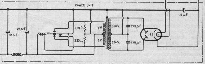
220R resistors damp transformer
primary.
In some timing circuits, a resistor of
typically 5 k to 15 k is connected in series with the capacitor (R21, 15
k, in the circuit below).
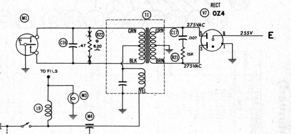
R21 damps leakage inductance oscillations.
Unfortunately, many texts erroneously assume the function of this resistor is to act as a fuse in case the capacitor shorts. This well may happen, but the power supply is then left operating with no timing capacitance, which unbeknown to the user is quickly ruining the vibrator. The supply should be fused to protect against capacitor failure.
In actual fact, as Mallory literature explains, the resistor is to damp oscillations caused by transformer leakage inductance.
Periods t2 and t4 show oscillations caused by transformer leakage
inductance.
In synchronous circuits, where the timing capacitance consists of two separate capacitors, resistors should be included where the rectifier contacts short circuit the capacitors. Typically 50 to 200 ohms, these resistors limit the capacitor discharge current when the contacts close. The fully charged capacitors would otherwise be short circuited directly, which is not only hard on the capacitors, but increases the possibility of sparking, and subsequent contact wear and RFI.
50R resistors limit timing capacitor discharge current.
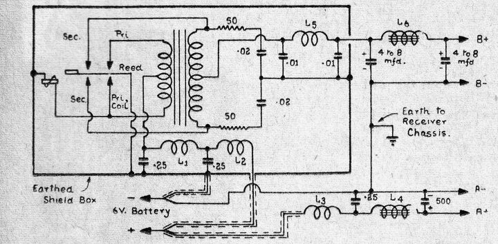
Chokes.
Because of the switching waveform being
rich in harmonics, RFI suppression is usually fitted in the form of L-C
filters. In the battery input circuit, these prevent radiation from the
battery supply leads, which would be picked up by the aerial. Additionally,
noise on the supply from the ignition system is prevented from entering
the receiver on the same supply leads. In the above circuit, the chokes
L1 and L2, along with the 0.25 uF capacitors, perform this function.
Depending on design, a similar L-C filter
may be present on the B+ supply for suppressing vibrator interference.
In the above circuit, this is represented by L5 and the associated 0.01
uF capacitors. This is in addition to the ordinary B+ smoothing filter
based around L6 and the two 4-8 uF capacitors. As with AC mains radios,
many later vibrator supplies used RC filtering for the B+ smoothing. Incidentally,
B+ filtering is actually easier than with an AC mains supply, since the
ripple is about 200 Hz instead of 100 Hz, and the flat topped waveform
with a high duty cycle means there is a lot less for the filter capacitors
to fill in.
On the subject of RFI elimination, the methods and design have to be taken on a case by case basis for each type of power supply. Some power supplies need more or less shielding and filtering than others. Layout of components, and flow of earth currents in the chassis are two aspects to consider. On this note, when restoring a power supply, use the original earthing points when replacing parts. Earth currents flow in the chassis, and using a different point can actually increase RFI. The RFI from a well designed power supply should be lower than the atmospheric noise level.