Valradio is an English company which specialised
in inverters. They still exist to this day. For many years I had seen their
advertisements, particularly in English magazines like Wireless World,
but also locally in Radio & Hobbies. Obviously, the inverters had also
been imported into Australia.
In more recent times, I found a service
manual for the inverters, and also a description of how they work was also
given in the "Radio And Television Engineers' Reference Handbook".
Then, I was offered one from a vintage
radio enthusiast from Queensland, for the cost of postage. Of course, being
a vibrator inverter I had to have it, but I was also curious about its
interesting design.
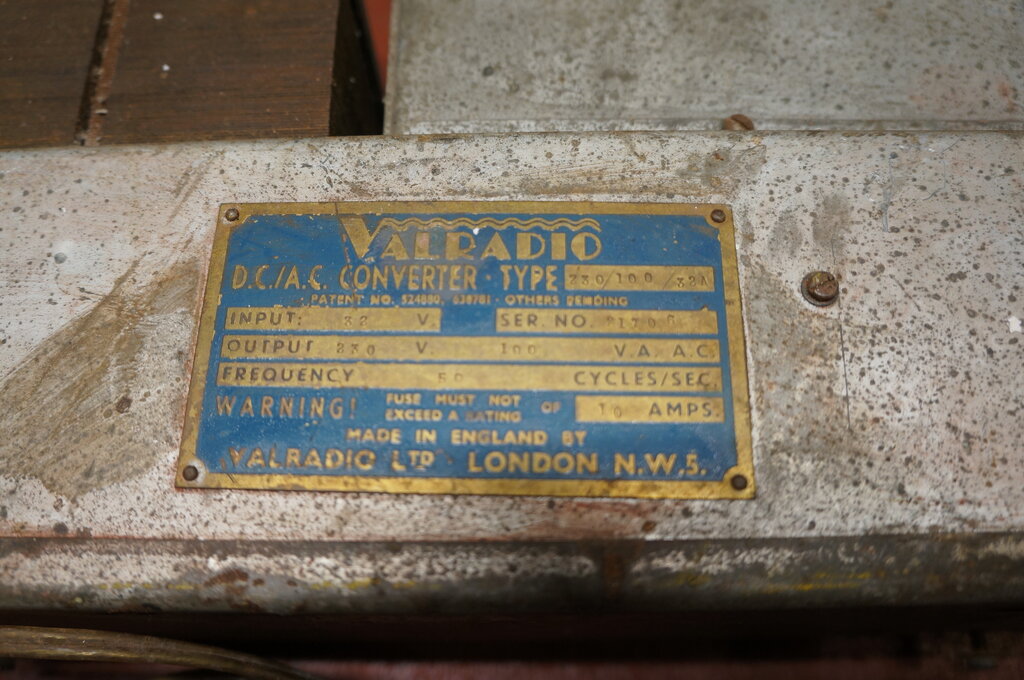
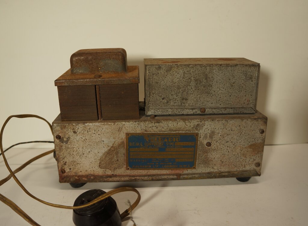
Model 230/100/32A. Input 32V, output 230V, 100VA, 50c/s.
It turned out to be a 32V model, rated at 100W. No doubt it had been used to run a radio or radiogram from a 32V lighting plant on a rural property.
As received, the 32V input was connected by a 240V 3 pin plug. Note
that the nameplate is not riveted on square.
The inverter is of the era where exposed
components on top of a chassis was a normal form of construction. The vibrator
and power transformer are mounted on top. Connection to the inverter is
via two lengths of plastic twin flex. One is for the 32V input, and the
other is the 230V output. A short single cloth covered wire is provided
for an earth connection.
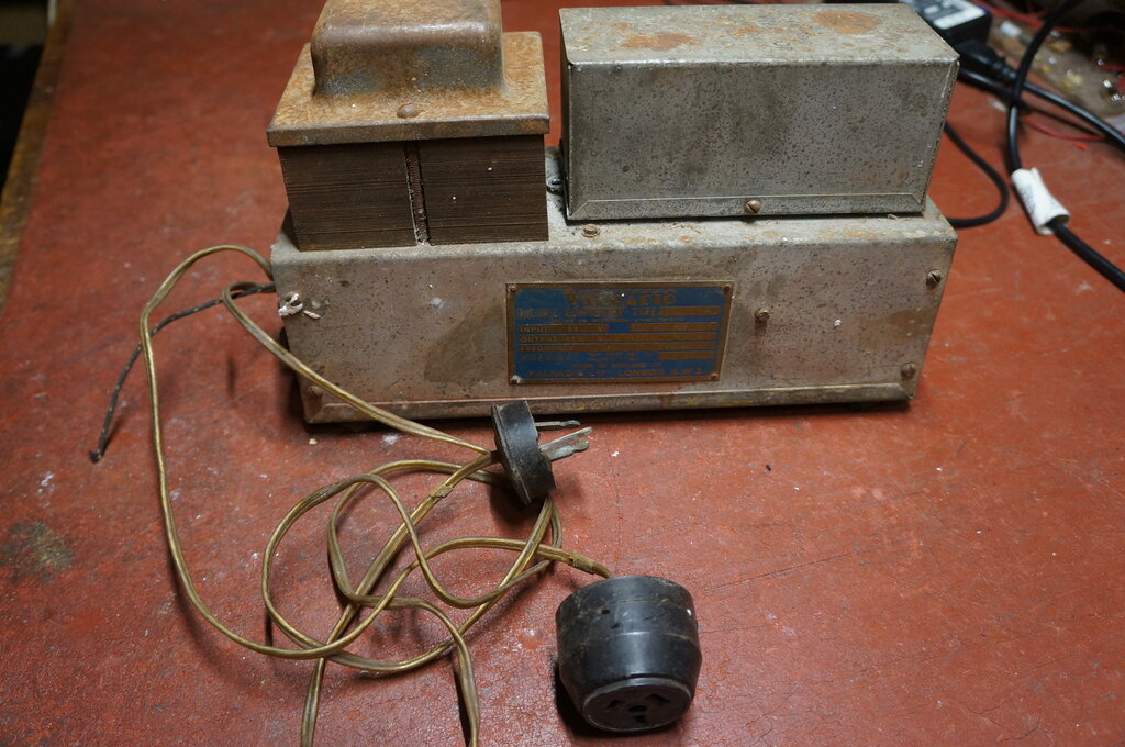
As is so often the case, a 240V 3 pin
plug had been fitted to the 32V supply lead. The output lead had connected
to it an HPM surface mount three pin socket. Presumably, a proper extension
cord socket was not available. Using a surface mount socket this way means
the connections are exposed at the rear, though in practice they're out
of the way enough that a shock is not likely. Nevertheless, it could have
been screwed to a piece of wood.
240V plugs on 32V equipment is an unfortunate
fact of life, and were often used because such fittings were more readily
available, than the correct polarised two pin type. Unfortunately, in the
modern day, such equipment is sometimes plugged into a 240V power point
out of ignorance. For radios, it results in a set of blown valve heaters
and dial lights. This inverter looked like it hadn't been used for such
a long time that I felt it had probably escaped the application of 240V.
The fact that one of the plug pins was bent probably helped discourage
anyone plugging it in.
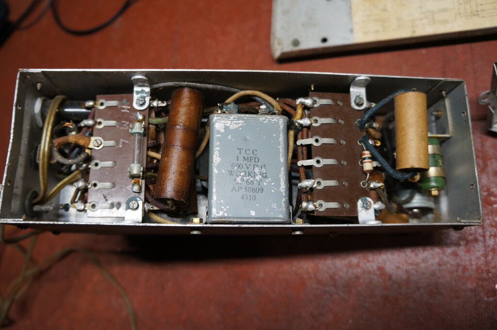
Under the chassis. 1uF timing capacitor visible in the middle. 20R
wirewound resistor is the green object at the right hand side.
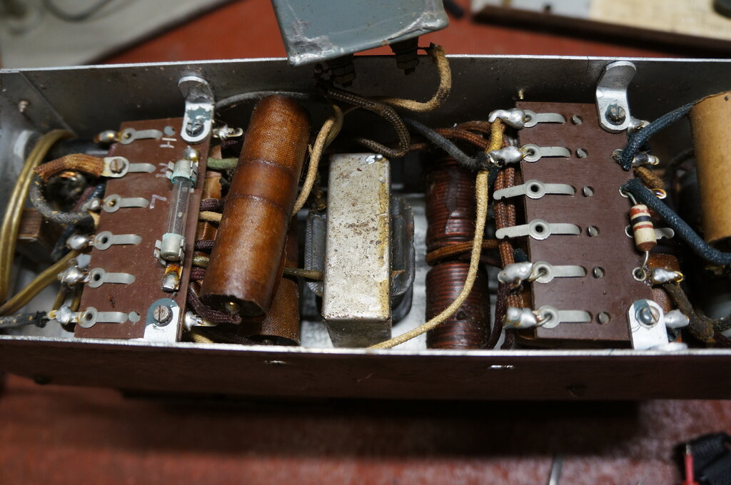
Output filter choke, L2, visible under timing capacitor.
A look under the chassis revealed a typical array of 1950's era components. At the left is the output voltage selection terminal strip and 15A fuse. No knots or any other clamping device had been provided at the cable entry, which is rather poor practice. All the strain is taken by the soldered joints.
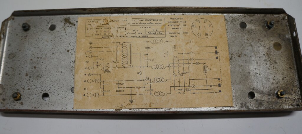
Circuit on bottom cover is not entirely accurate. The transformer
is double wound, not an autotransformer.
A nice surprise was the circuit diagram
attached to the bottom cover. Parts of it looked silverfish eaten, but
is still readable. However, this wasn't important since I had the full
manual. A few discrepancies were noted between the circuit as shown, and
the actual inverter.
In particular, the transformer shown is
an autotransformer. The actual transformer in the inverter is a double
wound type, which is also shown in the manual. Also, the timing capacitor
connects to the AC output wander lead, not permanently across the full
secondary.
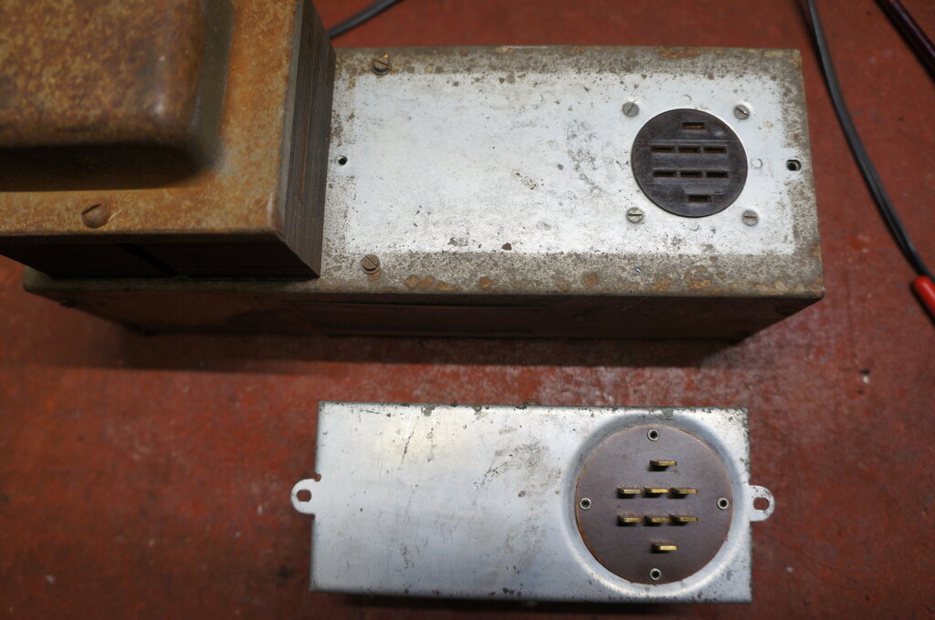
Unusual eight pin base for the vibrator.
Since, externally, the vibrator looked a lot like the Electronic Laboratories type, I had assumed it would be connected by one or two UX-6 valve bases. I was a little surprised to find instead a rather unusual eight pin base and socket.
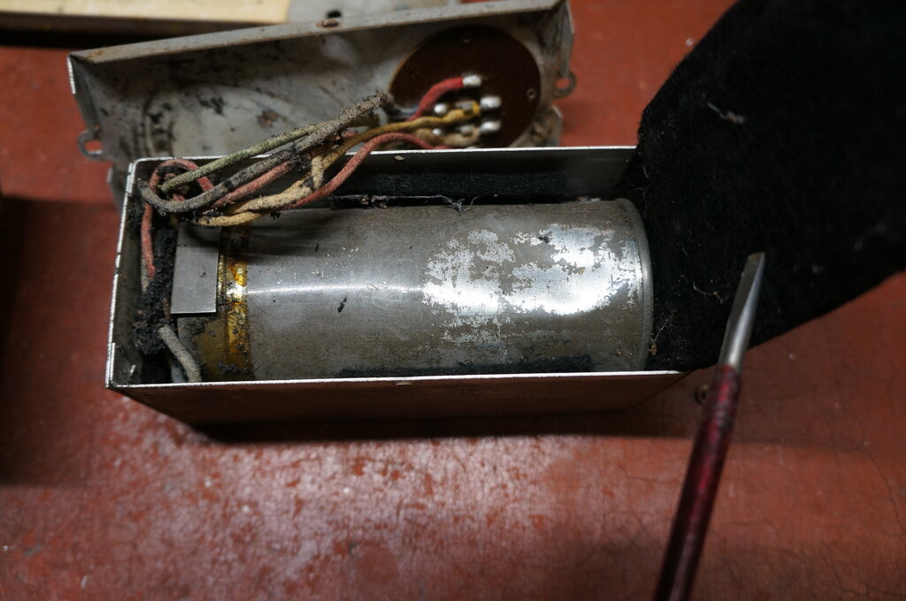
Cover removed from vibrator box.
I had expected when I opened the vibrator box that there'd be something resembling an E-L type, but instead there was a cylindrical vibrator of the ATR or Van Ruyten type. It was attached by flexible wires to the eight pin base, and surrounded by felt packing.
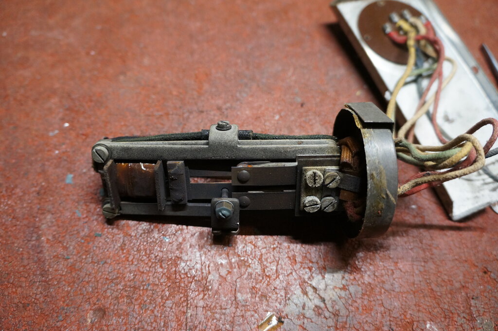
Inside the vibrator.
The can was easily opened since it was
just a press fit and secured by cellulose tape. Unlike most vibrators using
this type of can, it had not been secured by soldering. Surprisingly, there
was no acoustic insulation inside the can, but there was a black deposit
from many hours of use.
Incidentally, the vibrator can is almost
identical to that used by Van
Ruyten, except the VR vibrator is about 2mm smaller in diameter.
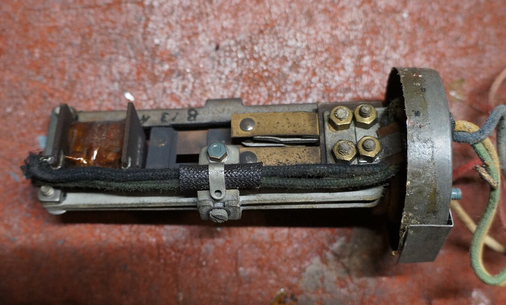
Close-up of vibrator.
The vibrator is a split reed type with
two sets of contacts, and as is typical for inverter use, is of the separate
drive type. The general construction is slightly different to what I've
seen before, having a kind of split frame for the mechanism. This apparently
is to allow adjustment of the coil relative to the reed. Also, the driver
contact passes through a hole in one reed to another contact mounted on
the same reed.
The mechanism is mounted on the can base
with grommets and nuts and bolts so that it can float freely. As I discovered
this was quite important. Since the mechanism is mounted horizontally,
it could be imagined that if the mounting grommets deteriorate, that it
will touch the side of the can.
The operation has been covered extensively
elsewhere, but suffice to say, the incoming DC is switched alternately
between the two sides of the transformer primary, creating an alternating
current. This is stepped up by the turns ratio of the transformer in the
usual way.
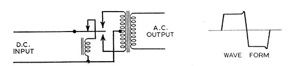
A limitation is that the output is mostly
a square wave, rather than a sine wave as supplied by the mains. Radio
and audio equipment operated off such inverters can be susceptible to hum
or buzz because of the steep waveform being rich in harmonics.
The Valradio circuit improves upon this:
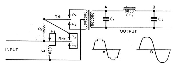
Valradio circuit.
A split reed vibrator is used with two
pairs of contacts. The contacts P1 and P2 are spaced slightly closer to
the reed than P3 and P4. As the reed swings upwards in the above diagram,
input current flows through R1 when the P1 contacts make, and the upper
half of the primary is partially magnetised. As the reed continues to swing
upwards, the P3 contacts make shortly after, and R1 is now short circuited.
Now full current flows, and the primary is fully magnetised.
When the reed begins to swing the other
way, P3 breaks first, introducing R1 back into the circuit, which at the
now reduced current, is finally broken by P1. The same operation occurs
with P2 and P4 respectively.
In summary, the initial primary current
flow is limited by R1, which is when the contacts are under the greatest
stress in the typical circuit. Then, once they have closed, full
current is applied. The result is a stepped increase in current when the
contacts close, and a stepped decrease when they open.
The main advantage is that contact stress
and the possibility of arcing is decreased due to the current limiting
and damping effect of R1. A by-product of this method of operation is also
that the output waveform now becomes more resemblant of a sine wave than
a square wave, as shown in figure A. Filtering by a simple L-C circuit
improves the waveform further, as shown in figure B.
This of course means that with harmonics
largely removed, filtering becomes easier, and hum and buzz are less likely
in the powered appliance.
If the concept of a split reed vibrator with the two sets of contacts opening and closing at sooner and later times sounds familiar, that's because it's exactly the operation of a self rectifying, or synchronous, vibrator. Indeed, it's an interesting thought to use a conventional synchronous radio vibrator in such a circuit. As shown, a split reed type (such as Oak V5211) would be used, but a conventional single reed type, such as the V5124, could also be used with two resistors; one for each contact. The normal primary contacts would take place of P1 and P2, with the secondary contacts used for P3 and P4.
The Valradio Circuit.
The link to the service manual is further
down, but since it covers many different models, it's easier for explanation
to show the 230/100/32A model with component values here first.
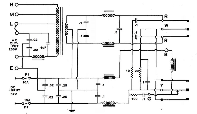
Circuit for the inverter described.
There are some slight differences with
the circuit of the actual inverter, compared to that in the service manual,
and also that which was glued to the inside of the bottom cover. However,
the principles of operation are not affected.
R1 in the previous theoretical circuit
is 20 ohms. This is the green wirewound resistor that can be seen under
the chassis on the right side. Power rating of this resistor looks to be
about 20W.
There is an RC network across the driver
coil contacts consisting of a 100R resistor and 0.1uF condenser. The service
manual has 33R for this resistor, but the circuit in the unit shows 100R,
which is what is actually present.
The 10R resistor in series with the junction
of the two 0.1uF's for the upper vibrator contacts was not visible; perhaps
obscured by one of the tagboards. From what I could see, it looked like
it didn't exist.
Timing capacitance consists of the 0.5uF across the primary, and the 1uF across the secondary. Note that unlike the service manual circuit, and that which is in the unit, the 1uF is not connected across the full secondary, but across whatever output tapping is chosen. This means the timing capacitance effectively changes depending which tapping is used.
Output filtering is achieved with the iron cored choke in series with the AC output. Compared to the theoretical diagram, the two .02uF's would have virtually no effect with regards to the wave shaping. They would suffice for RF filtering only. The output voltage of 230V is nominal only, and adjustable over about +/- 30V with the High, Medium, and Low tappings. The loading of the appliance, the lead length to the battery, and whether or not the battery is being charged while the inverter is operating, all affect the output voltage, hence the need for adjustment. Output is floating, with neither connection directly earthed.
Around the circuit are four air cored chokes
and various bypass condensers for RFI suppression. The chassis is floating
DC-wise, although if the earth wire is connected to an earth rod or metal
underground water pipe, it will be at earth potential for RF. Being a vibrator
inverter, input polarity is unimportant. In fact, there is no polarity
identifier on the input twin flex. The switch is not shown, but is in series
with one of the 32V connections. Two fuses are provided; one 15A inside
the inverter mounted on one of the tagboards, and the other is a user accessible
panel mount type of 10A. One may wonder why the two fuses, and of different
values, when they're both in series with each other.
This is to protect the inverter from the
user doing the wrong thing. If the inverter is overloaded, the 10A panel
mount fuse will blow first. Assuming the owner replaces it with the correct
10A fuse, the inverter will function again. If the owner replaces it with
an inappropriate fuse such as 20A, or wraps the blown fuse in aluminium
foil, and the inverter is overloaded again, the internal 15A fuse will
take over.
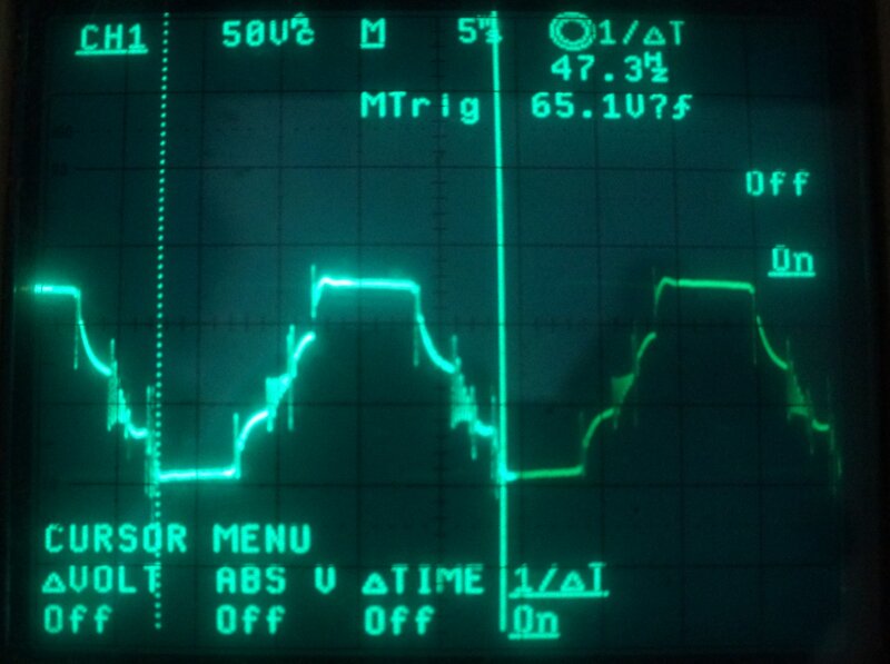
Waveform across transformer primary under load with 60W bulb. Frequency
was slightly low.
When measured, the output voltage was a bit low, but was easily fixed by moving the output tapping from Low to Medium. Either the inverter had been used with slightly more than 32V (e.g. 40V on charge), or the vibrator contacts were worn. Checking with a feeler gauge showed they weren't too badly worn, although at rest the gap on one side is a lot less than specified. It could be because of the peculiar reed drive that once the vibrator is operating, that the gap evens out. It certainly looks that way from the waveform.
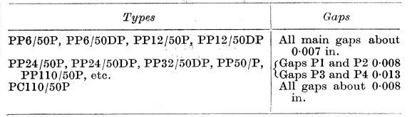
Contact gap settings for Valradio vibrators.
Interestingly, the contact gap setting specifications are not shown in the service manual, but are shown in the article in the Radio And Television Engineers' Reference Book. Apart from setting the gaps statically, it advises best results are obtained with a CRO.
In any case, there was plenty of adjustment with the output tappings; roughly about 30V between each tapping, so it was not felt worth restoring the vibrator contacts.
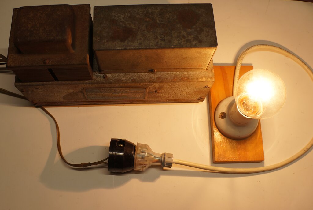
Inverter powering 60W incandescent bulb.
The cadmium plating of the whole inverter
is showing a bit of rust, as is the transformer cover, but I decided not
to do a cosmetic restoration at this time. I did however replace the rubber
feet; two of which were missing altogether.
Since I don't have a 32V system, this
exercise was mainly learning about the inverter and seeing how it performs.
If I was to put it into regular use, a cosmetic and electrical restoration
would be in order. The vibrator would be rebuilt with the contacts cleaned
and set correctly, and some of the paper capacitors might be replaced.
And I'd secure the cables!
It was noted the output frequency was
47.3Hz. The reed weight affects frequency, and it was observed that calibration
is achieved by weighting the reed with solder. Removing solder would raise
the frequency back to 50Hz. However, I would only do that after adjusting
the contacts.
I tested a few loads. Incandescent lamps
worked well, as did a valve radio. The inverter does not like fluorescent
lamps, even if power factor corrected. Contact arcing was quite unacceptable.
The only thing I can put this down to is combination of the inductance
of the output filter choke, and the reactive load. (A power factor corrected
fluorescent lamp is still not completely resistive). However, we can't
complain, since this inverter was specifically designed for electronic
equipment.
The inverter emits the same level of mechanical
buzz as my other 50-60 cycle inverters. You would want it in another room,
from where the radio was that you were listening to.