This radio came to me for repair from an
owner of a 1946 Ford Mercury. The complaint was simply that it stopped
working. My immediate curiosity was what kind of condition the radio was
in. Had it been restored in the past? Was it all original and had simply
survived this long? Was it full of paper condensers which had slowly killed
the vibrator?
This I wouldn't know until I actually
saw it; all I knew it was made by Tasma. This Sydney based company was
named after Thom and Smith. Their radios were popular, and the company
existed until the early days of Television. I have seen many types of vintage
car radio, but never one made by Tasma, so I had no idea what to expect.
Interestingly, Tasma was for a time, contracted to make radios for Ford.
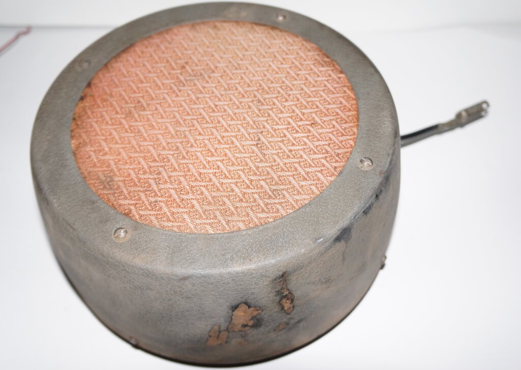
Separate 8" speaker.
The owner told me the radio was 6 volt
positive earth. I was pleased to hear this, because my number one pet hate
in the vintage car world is the "conversion to 12 volts". This comes about
because wiring in poor condition miraculously comes good with the application
of 12V, and the owner then believes that 6 volts was a design fault. Other
excuses to install a 12V battery are because 12V light bulbs and batteries
are supposedly easier to get. Then there's the "brighter lights" excuse
- again the result of poor wiring will indeed make a 12V system appear
to be the solution to the problem. Unfortunately, the poor starter motor
is expected to cop the higher voltage; the excess current, and higher torque
stressing the Bendix and ring gear conveniently overlooked.
The irony with all this is that some people
do realise that resistors should be put in series with the things which
can't be replaced with 12V equivalents, such as wiper motors, horns, etc.
The value of resistor is seldom chosen correctly, since the installer usually
has no idea about Ohm's law. Even when chosen correctly, half the power
fed into the load now just goes up in heat from the resistor. What a lot
of work and inefficiency, to get the voltage back down to what it would
be if the correct 6V battery was installed! Experience has shown it's useless
to argue, and I think how well the 6V electrical system works without any
problems in my own car, and those of friends.
Anyway, back to the radio; the question
of polarity was something I noted when the owner said positive earth. That
was standard with Ford from the 1928 Model A, up until they switched to
12V in 1954. Most valve car radios are polarity independent since they
use a non-synchronous vibrator. In a few instances there might be electrolytic
filter capacitors across the incoming battery supply, or the set might
use a synchronous vibrator. In these instances, the input polarity is important.
Whether or not this was applicable to the Tasma, I had no idea yet.
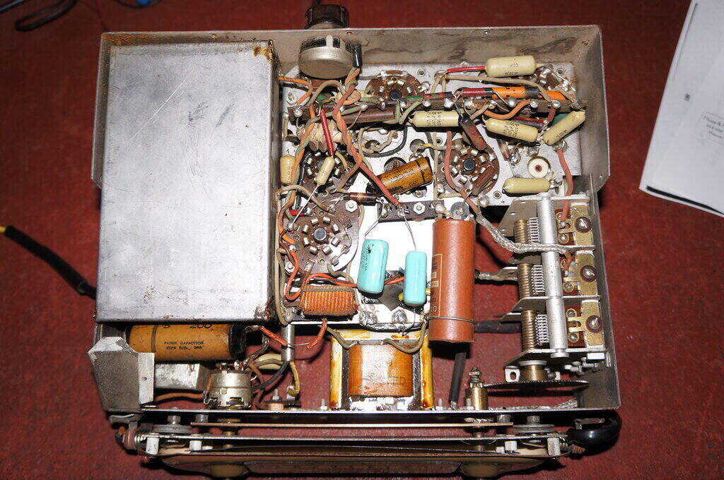
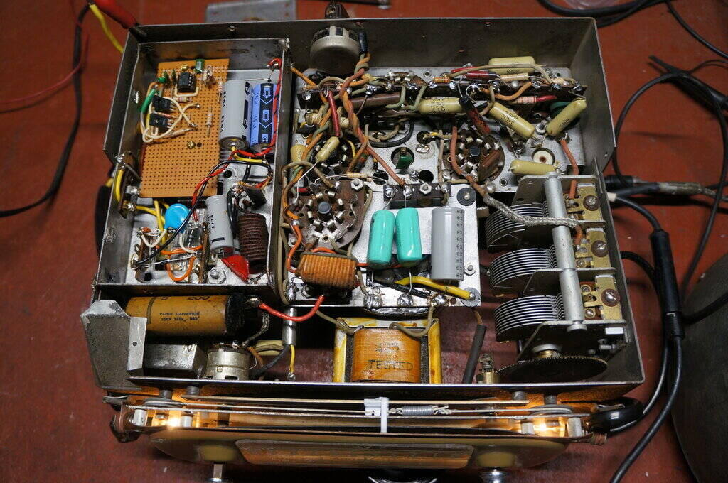
In due course the radio turned up, and
once the covers were off, all was revealed. It is a large set, and very
well laid out with good access.
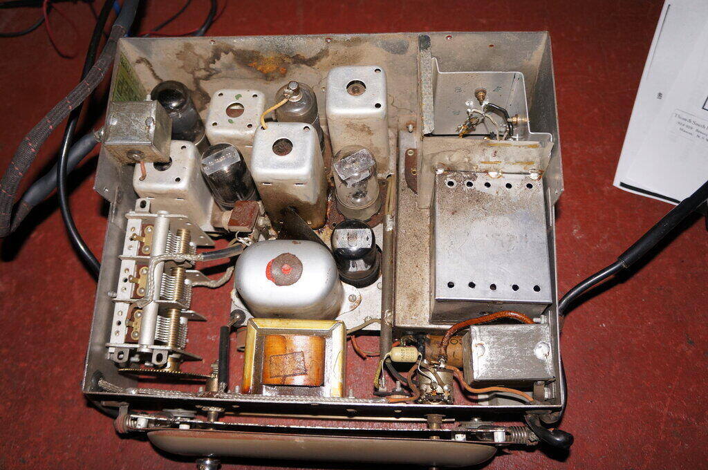
Good clean condition inside, but the first thing that stood out
was the vibrator replaced by transistors.
Not surprisingly, it used octal valves, since it would be a few more years before seven and nine pin miniatures appeared in Australian radios. One glaringly obvious thing stuck out like the proverbial - the vibrator and rectifier valve had been removed, with solid state circuitry put in their place. Two TO-3 transistors had been mounted on a bracket where the vibrator once was. It was certainly polarity dependent now! Good thing the owner had told me it was still positive earth, although I would have discovered this once the power supply circuit had been traced out.
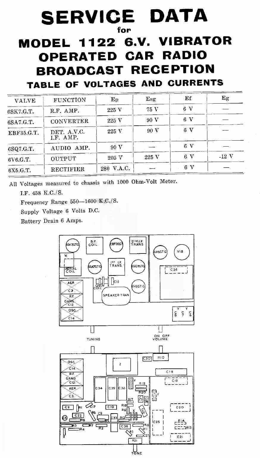
The model was 1122, the circuit of which I had in my AORSM listings. This was convenient so I didn't have to trace out the circuit of the whole set.
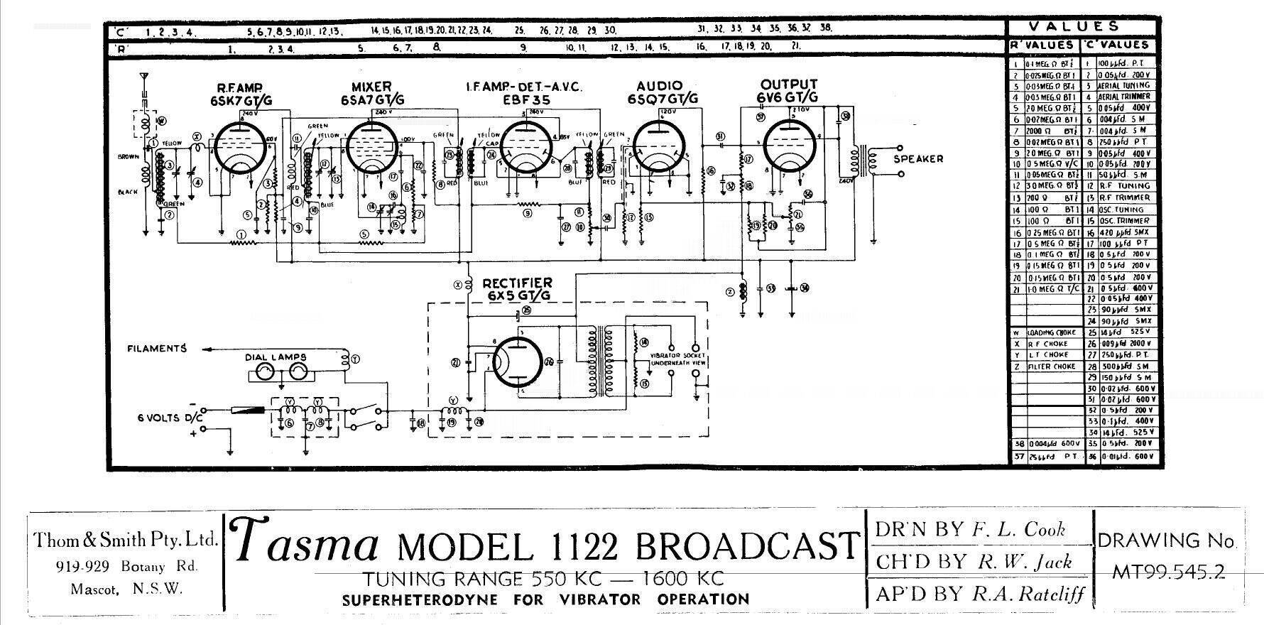
The circuit is as straightforward as one
can get. There is nothing peculiar about the design. The 6SK7 RF amplifier
feeds a 6SA7 converter. The 458Kc/s IF is then amplified by an EBF35, and
detected by the diodes therein. The volume control (30) and 250uuF (27)
forms the diode load. AVC voltage is developed across the diode load, and
feeds the grids of the IF amplifier, mixer, and RF amplifier, via resistors
9 and 1. A close look at the 6SA7 oscillator circuit shows the grid leak
is actually two resistors; 20k (6), and 2k (7). The junction of these two
resistors provides a small negative voltage (about -0.4V), as a result
of the grid current flowing from the oscillator coil. By using this voltage
to bias the RF amplifier, mixer, and IF valves, it means that individual
cathode resistors and bypass condensers are not required for each of these
valves. It also provides the AVC delay voltage.
Using the local oscillator grid voltage
for bias and AVC delay is not an uncommon scheme, particularly where the
power supply design does not provide a negative voltage.
Being of 1946 vintage, the front end is
tuned with a variable condenser; this being a three gang type because of
the RF amplifier. By the mid 1950's permeability tuning was becoming standard.
The audio from the volume control is amplified by a 6SQ7 triode; the diodes being unused. The signal then proceeds to the 6V6 output valve. This has an interesting feedback circuit incorporating a tone control. Plate voltage from the 6V6 is fed to the 6SQ7 cathode via a voltage divider consisting of two 150k parallel resistors (75k) and a 200R cathode resistor for the 6SQ7. It will be noted that 200R is too low to bias the 6SQ7, and that the 3M grid resistor is too low for contact bias to occur. Instead, the current flow through the 75k resistance causes the the voltage across the 200R to be higher than it would otherwise be. The negative feedback network is made frequency selective by a 1M pot (21), a 0.5uF condenser (35) and a 0.01uF condenser (36). If the pot is turned towards the 0.01uF, this value of capacitance will be effectively across the 75k and higher frequencies will have an easier path into the 6SQ7, thus reducing its gain, making the tone appear "mellow". Alternatively, when the pot is turned towards the 0.5uF, this value of capacitance is effectively across the 200R cathode resistor, only allowing low frequencies to be fed in, reducing its gain, thus making the tone appear high.
The power supply of the original design
is based around a non-synchronous vibrator. Given when the set was made,
and that it uses a four pin vibrator with a series drive contact, it would
most likely have been an Oak
V5105. Two 100R damping resistors are connected across the primary.
The timing capacitor is 0.009uF (26), and the rectifier is a 6X5.
An interesting feature is that the B+
filter choke (Z) is connected between the transformer centre tap and earth,
rather than the usual position between the positive terminals of the two
filter capacitors (25) and (34). Electrically, it operates exactly the
same, but there's two advantages doing it this way. Firstly, the insulation
stress between the choke winding and core is a lot less; being only a few
volts rather than the full B+. This reduces the chance of a breakdown,
and the wire is less likely to corrode because of electrolytic action.
Secondly, the voltage drop across the
choke is now negative with respect to earth, and this can be used as a
source of bias. It works exactly same as the usual back bias resistor.
In this circuit, it's used to bias the 6V6. Because of the high DC ripple
across the choke, this voltage has to be filtered first, and this is done
by the 100k (18) and 0.5uF(32). However, it must be kept in mind that the
resistance of the choke is important since it determines the bias voltage.
Any replacement must be the same resistance or the 6V6 will be incorrectly
biassed. Chokes of other resistances could be used by means of an extra
resistor, either in series or parallel with the choke as the case may be.
It's interesting to speculate why, with
this back bias circuit, it was not also used for the front end valves instead
of the 6SA7 oscillator grid voltage.
Another interesting thing to note is polarity
designation on the 6V supply. This set as manufactured would be polarity
independent, but it's marked as being for positive earth. This suggests
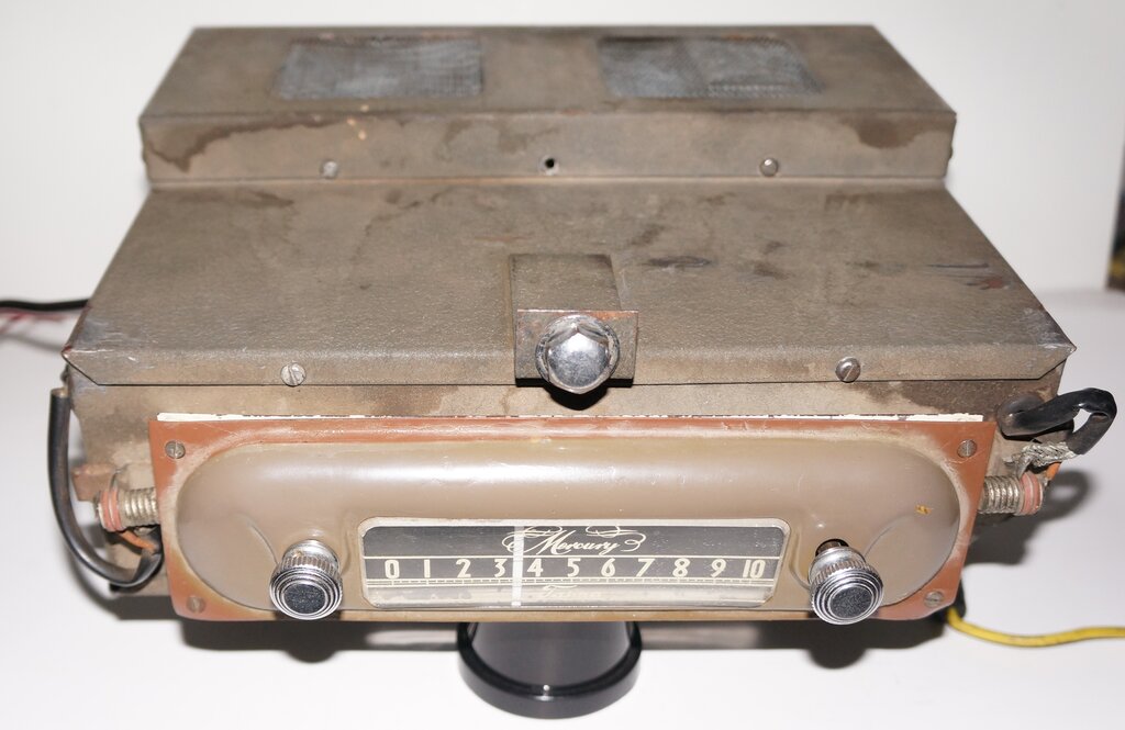
that the 1122 was only made for Ford. Certainly, the dial plate fitted
to this set is specific for the 1941-1946 Ford radio dash cut-out.
A previous restorer had saved me a lot of work by replacing most
of the paper condensers.
The radio had been restored sometime in the past. Most of the paper capacitors had been replaced, along with the previously mentioned solid state power supply. One thing the owner wanted me to do was to replace the dial cord and pointer, for these were missing. How this came to be will never be known. Our restorer had been working in this area of the set, since there were a couple of out of place Philips screws on the dial backing plate. Maybe he thought it was too hard and gave up? In any case, the tuning capacitor is driven directly from the tuning knob by a simple gear reduction, so the dial string is not actually required to tune the radio. As with many car radios of the era, a simple 0-10 tuning scale is provided with no frequency, wavelength, or station calibrations. It's an easy way out of trying to fit all the Australian call signs onto a small dial.
Out of curiosity, I powered up the radio with a 6V 10A regulated supply, and was surprised when sounds issued forth. The sensitivity was a bit low, but it certainly wasn't dead. I can only assume there was something wrong with the 6V feed in the car, or there was some intermittent fault in the set (I hoped not!). The volume pot with on/off switch had been replaced in the past. Confusingly at first, it wasn't realised that the on off switch was a push/pull type. This type was never popular, and it's easy to imagine many being damaged by trying to turn the radio off in the normal way, feeling for the non existent "click" as the control is rotated anti clockwise.
At this stage the things needed to be done were:
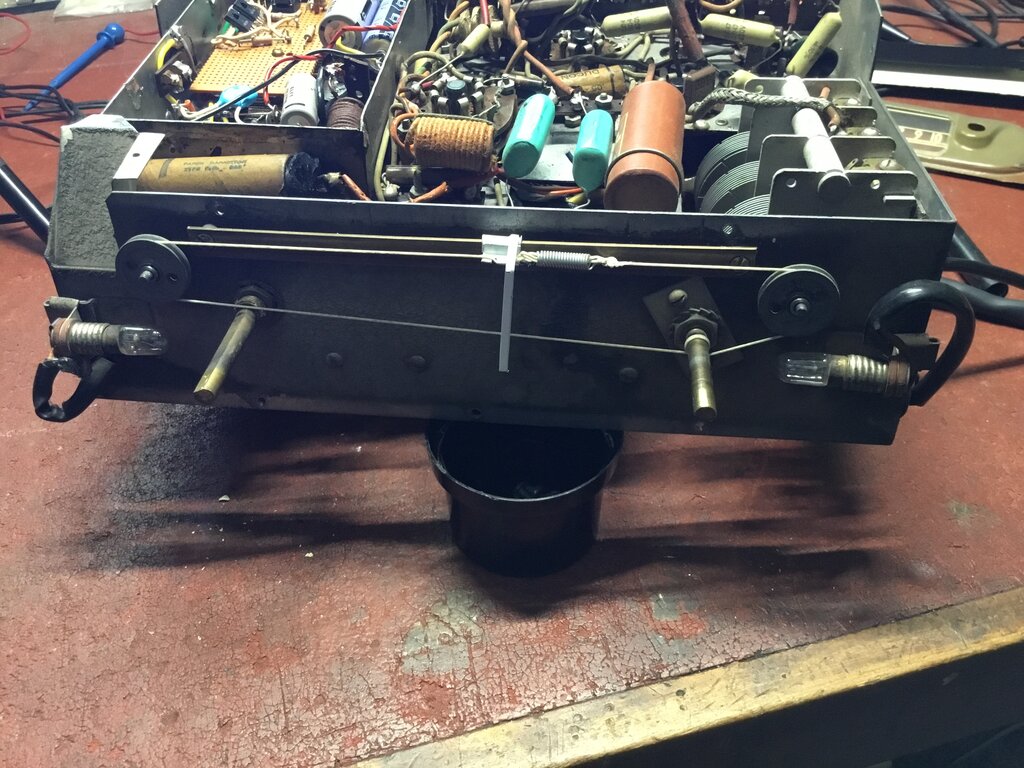
New dial string and pointer.
Admittedly, the workmanship of what had
been done to the Tasma was actually very good, and I have nothing to criticise
on that level. In fact, our previous restorer had done a very good job
of it, and must have taken quite some time. He had made up a heatsink bracket
for the 2N3055's, a shield around them, and spent a while building up the
rest of the circuit on a piece of Veroboard. Still, it was a lot of work
just to avoid using a vibrator. To be honest, my guess is that many valve
radios, fitted to vintage cars in the present day, are actually using a
solid state power supply.
Even if the vibrator had been missing
from the set, that's no excuse to use a solid state substitute, in the
modern day. While they only sometimes appear on the Australian eBay, a
search on the U.S. eBay always brings forth plenty of 6V vibrators.
However, we must take into account when
this set was restored in the 1980's, vibrators were actually very
difficult to get in Australia. I know because I was always trying to find
them! It's only once I joined the HRSA, and then later when the internet
appeared, that it became much easier to obtain them.
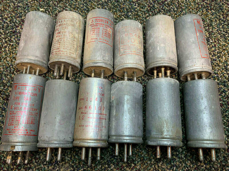
This lot of vibrators was only U.S. $17.75 on eBay, and is typical
of what turns up. Any of the 6V types here could have been used in the
Tasma.
As mentioned previously, it appears the set originally used an Oak V5105 vibrator. Of all the vibrators used in Australian car radios, these Oak non-synchronous types are the easiest to restore, and when used correctly, extremely reliable.
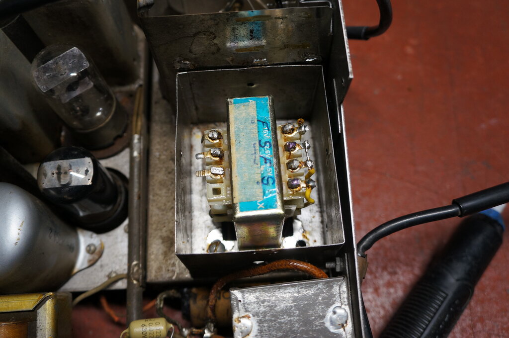
Transformer is a rewound 2155. Note the finish and start designation
for the new windings.
One puzzling aspect of the modified power
supply was the transformer. I was surprised to see something modern - a
2155 type used in reverse. To readers outside Australasia, the 2155 transformer
is a 1A type with secondary tappings from 6.3 to 15V. It's been used in
countless magazine projects since the late 1960's, and is still available
from component suppliers. This one had obviously been rewound. When used
in reverse, the original secondary becomes the new primary, and vice versa.
Our restorer had dismantled the transformer and replaced the low voltage
winding with something more suited to the 6V supply. There's nothing wrong
with this; in fact I've done the same myself as shown here
and here.
My puzzlement is why the original had
been replaced. The original vibrator transformer would be quite OK driven
by solid state circuitry, so I can only assume it was faulty. Since the
2155 has a single 240V primary (now secondary) winding, it precludes using
the original 6X5 rectifier valve. It does seem the 6X5 had been tried with
the original transformer, since one of the heater wires was still connected
to the socket, which was modern PVC. Since the 6X5 can't be used in full
wave with a single secondary winding, a bridge rectifier consisting of
1N4007 diodes had been installed. (Yes, the 6X5 could be used in half wave,
but efficiency and output voltage would be lower for a given secondary
voltage).
Sliding a mirror down beside the switching
transistors showed they were 2N3055's; a typical choice. They were dated
1980, which gives some idea as to when this radio was previously worked
on. The components used in the power supply look like they're from this
era or a little bit later. As to what drove the 2N3055's, there was a piece
of Veroboard with a 555 and BD139 and BD140 transistors. This all seemed
more complicated than need be; the 2N3055's could be simply connected as
a free running cross coupled circuit, along the lines of this
inverter.
As a related issue, it should be pointed
out that many types of 'solid state vibrator' can actually be harmful,
since they feed the transformer with a 100% duty cycle. This can cause
core saturation because of the longer time which current flows, and at
the least, the output voltage will be higher. Better designs provide a
proper 80% duty cycle.
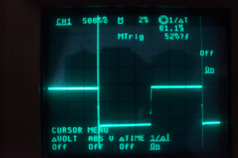
Frequency of the inverter is 81.1Hz. Measurement taken at 2N3055
base.
Of course, I had to trace out the circuit of this concoction; the unnecessary complexity having aroused my curiosity. As I discovered, the fuse fitted was 20A which is way too high, so this was replaced with a more appropriate 10A type.
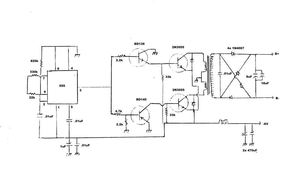
How the Power Supply Works.
Someone had gone to a lot of effort to avoid using the original
vibrator power supply.
To help understand the circuit, it must
be remembered that the earth is positive and the supply line is negative.
The earth symbols are therefore +6V.
The 555 generates an 81Hz square wave.
When pin 3 goes high, base current flows through the BD139 via the 2.2k
resistor. The emitter current then flows straight to the base of the upper
2N3055, switching it on, causing current to flow in the upper primary winding.
At the same time, the BD140 remains off
because the base is not biassed on, and the lower 2N3055 does not conduct.
When pin 3 of the 555 goes low, the BD139
is no longer receives base current and switches off, causing the upper
2N3055 to also switch off. The BD140 is now biassed on, with current flowing
from the emitter, via the 4.7k base resistor, and to the negative supply
via the 555.
Thus the lower 2N3055 switches on, and
the magnetic field in the transformer core reverses.
The AC so generated is stepped up by the
turns ratio of the transformer, and rectified with four 1N4007 diodes,
and filtered with an 8uF and 16uF condenser. Output voltage is about 208V
under load. With no load the voltage is around 355V. The filter capacitor
arrangement is strange. 16uF on its own would be more than enough; or quite
possibly just the 8uF. Both together is overkill, especially for filtering
a square wave.
Back EMF suppression diodes are connected
between the collector and emitter of each 2N3055. The numbers were not
visible but are 1A types, probably 1N4007. Aside from these, there is nothing
to protect any of the circuitry against reverse polarity. Why the -6V supply
is filtered with two 470uF's is curious when a single 1000uF would do the
same. Perhaps it's just what the restorer had available. I would think
these capacitors would be more effective on the other side of the choke.
Once the circuit had been traced out, it
was not clear what was actually limiting the 2N3055 base current. One would
assume that if the BD139 or BD140 was switched on, that the 6V supply would
be fed directly into the 2N3055 bases. Since the base-emitter junction
allows only something like 1V, then clearly excess current would flow.
The power supply had obviously worked for many years, so something must
be limiting the current. I connected a 10R resistor in series with one
base and observed the voltage across it.
Only about 74mA was flowing. Other measurements
seemed to indicate that the current was simply being limited by the BD139/BD140
combination, which were not being run as saturated switches, but with the
degree of conduction set by their base current, in turn set by their associated
base resistors, and the 555 output resistance (100 ohms - high; 10 ohms
- low). It all seemed a matter of luck, because if for example, the BD139/BD140
transistors were replaced with ones having different current gain, the
2N3055 base current may be too much, or it may be too little.
Measuring the base-emitter voltage of
the 2N3055's was interesting. 1.12V seemed high considering this was a
silicon diode junction.
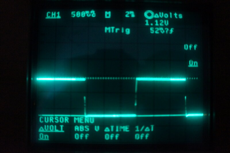
Base-emitter voltage of the 2N3055's.
It turned out too that the 2N3055's weren't being driven to saturation, since their Vce was 1.72V. I thought that 74mA base current was a bit low, and so it turned out to be.
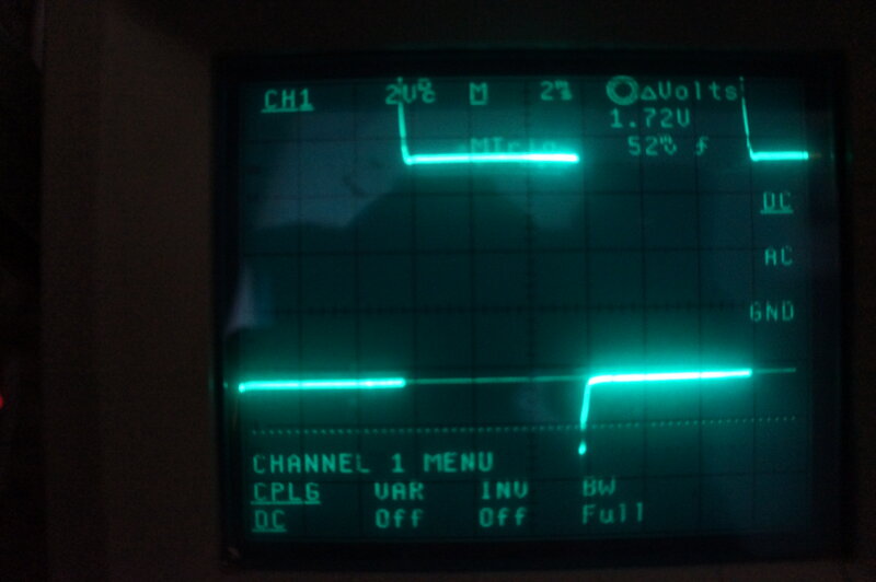
The dotted line is the emitter reference; the solid line being collector
voltage. The emitter never has less than 1.72V across it.
There's an irony that the loss of 1.72V
across each transistor is a lot higher than it would be if the vibrator
had been retained. In fact, it's approaching one third of the supply voltage!
While I don't condone solid state vibrator
circuits, I would have done it differently. Of course, if it was my own
set I would have restored it back to using a vibrator.
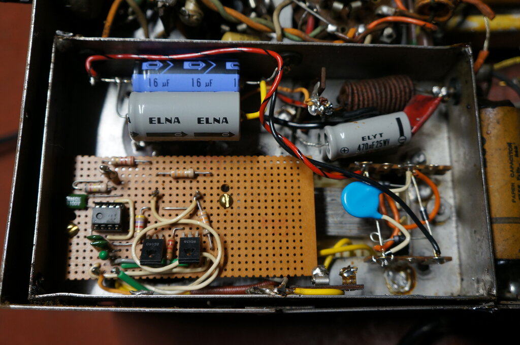
Power supply circuitry built on Veroboard.
I could have redesigned the solid state circuit to work more efficiently, and with proper control of the 2N3055 base current, but it seemed pointless since everything was working, and no components were operating outside their rating. Importantly, it was obviously reliable since having been installed some time ago. But good design? Not really. I wonder where the circuit came from, since I've not seen it amongst the inverter/solid state vibrator circuits I've seen published.
Capacitors and Resistors.
There were two remaining paper condensers;
a 0.05uF AVC bypass, and a 0.5uF across the 6V supply. The 0.05uF was replaced
since although the voltage across it is low, the resistance of the associated
circuit is high. Leakage here would cause insufficient bias for the front
end valves, as well as reducing the effectiveness of the AVC circuit.
The 0.5uF was left in situ as even severe
leakage will have no effect on anything, but also it was a special low
inductance type; this being evident by its terminations being of braid
rather than the usual tinned copper wire. The original Ducon second filter
electrolytic was replaced even though it tested OK. Any electrolytic this
old can no longer be counted on, despite this particular type being usually
very long lasting. It's not worth taking the risk of having it fail when
it is so easily replaced.
The resistors were all of the body-end-dot type. Most of them had gone high and were replaced. This was not a difficult job since the leads had not been twisted around the tags.
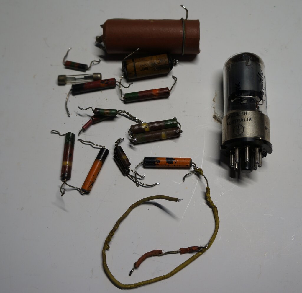
Parts replaced.
Speaker Transformer.
It was noticed while doing this work that
the speaker transformer had been replaced in the past. Not only was it
dated 1949, but it was a push-pull type with the second plate wire cut
off. Using a push-pull output transformer in a single ended circuit is
not the correct thing to do.
This is because with a push-pull transformer,
the laminations are interleaved with no air gap. When DC is passed through
one winding, the core can begin to saturate, reducing inductance. When
the transformer is used correctly, both windings have the same amount of
DC passing through them in opposite polarity, and the magnetic field cancels
out. In the case of a single ended transformer, the laminations are arranged
in an E-I formation, and an air gap is provided to prevent core saturation.
It's not a matter of it working or not
working with the incorrect transformer, but a question of efficiency. Since
the transformer had been in the set this long, and no one seemed to notice
any problem, it was felt there was no point in replacing it. The negative
feedback circuit would go a long way to correcting any deficiencies, and
the limiting factor would likely be a small reduction in power output.
Replacement of resistors and capacitors complete.
Valves.
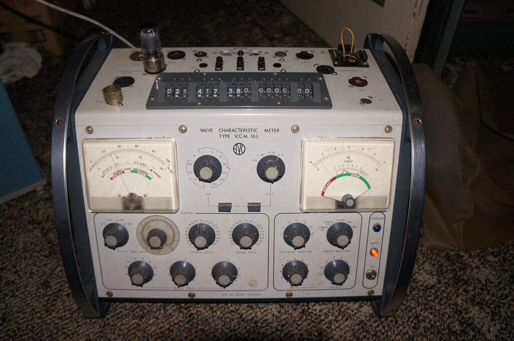
Putting the valves through the AVO VCM163
valve tester showed that apart from the 6SK7, they were all in very good
condition. The 6SK7 was down in emission, and while this would not be a
problem driving around near the transmitters, the gain of the set would
be less than it should be, and this would show up driving in distant rural
areas. A new 6SK7 was ordered.
All valves were Philips Miniwatt, except
for what was in the EBF35 socket. In its place someone had installed an
AWV 6AR7GT. This has the same pin connections, and is the same type of
valve, so is an acceptable substitute. In fact, the gain is higher which
is a good thing, provided it doesn't cause instability. The 6AR7GT is a
valve unique to Australia, having been designed by AWV. Its notable feature
is the permanently attached lead shield. The EBF35 and other Philips valves
use a conductive spray coating, which while effective, is easily damaged.
6SK7 RF amplifier is weak.
Alignment.
A 458Kc/s AM signal was fed into the set
and the IF alignment checked. It had drifted and the gain was brought up
considerably when the bottom cores of both IF transformers were adjusted.
Possibly the substitution of the 6AR7GT for the EBF35 had a slight effect,
should the internal capacitances be slightly different. The cores were
quite loose, and so were sealed with a drop of polystyrene cement - strong
enough to hold the adjustment, but easy to break if required.
The trimmer for the local oscillator needed
adjustment to get the correct 1600Kc/s upper limit for the band. The oscillator
coil is air cored and non adjustable, so only the upper frequency limit
can be set, short of providing an adjustable padder.
The RF coil alignment was checked at 600Kc/s,
and then the RF trimmer adjusted at 1500Kc/s.
Finally, the aerial trimmer was peaked
at 1500Kc/s.
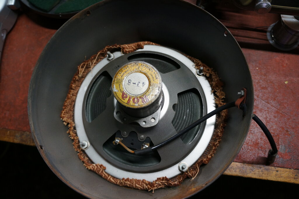
Inside the speaker.
Conclusion.
Throughout the work on this set, I had
a hard time trying to think of any other car radios I've worked on, which
have been as pleasant as this one. The Tasma has been really well designed,
and I can't criticise any aspect of it. The parts are nicely laid out,
with nothing crammed into tight spaces, and everything is accessible. The
absence of component leads twisted through tagstrips and valve socket pins
was particularly welcome.
It's just a shame the vibrator power supply
was replaced with solid state circuitry - but unless you're obsessive about
such things, the new circuitry does the job perfectly well.
Performance is typical, with good sensitivity.
I was able to receive 2LT from my house, about 60km distant, with an ordinary
car aerial. 2LT has a directional transmitter, with its signal aimed in
the opposite direction, so it's always a good test of sensitivity. 2CR
was also received. It's an ABC transmitter at Cumnock, near Orange. Sound
quality through the 8" speaker is good, and the tone control works very
well.