Back in the late 80's when I had become
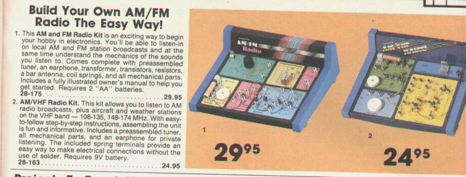
interested in super-regenerative receivers, I was aware that the cheap
AM/FM radio kits being sold by Tandy ("Radio Shack" for our North American
readers) used a super-regenerative receiver for the FM part. I kept on
promising myself I'd buy one, but never got around to it. Eventually, Tandy
was taken over by Dick Smith and no longer had its usual catalog items.
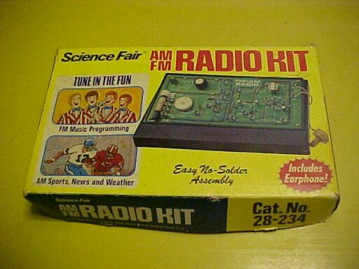
So, I bought this one from eBay. I decided on the 28-234 as it had a plastic
chassis; far more rugged than the later and more common 28-175 with its
cardboard construction.
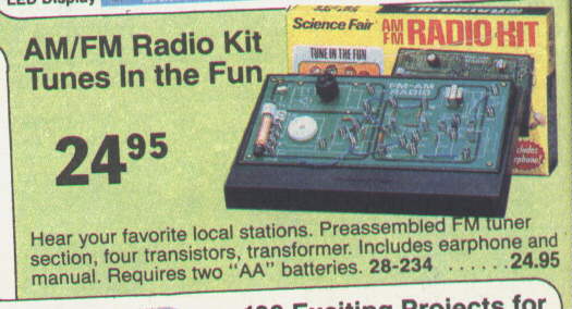
From the 1983 Tandy catalog.
These AM/FM kits did not appear in Australian
Tandy stores until the early 80's, unlike the Radio Shack stores in North
America where they'd been around since the 1970's. The reason for this
is that commercial FM broadcasting did not start here until the end of
1980. There were a few ABC and community stations which had existed prior
to this when FM transmissions were allowed again in 1974. There were unofficial
transmissions by the ABC from 1947 until 1961, but the PMG used the excuse
that the FM band was needed for the new television channels (3,4, and 5)
to shut them down. There was also pressure from commercial AM broadcasters
not to have FM due to perceived loss of audience. In reality, there was
no technical reason to stop the FM broadcasts as there were still spaces
unoccupied by TV channels, and not all areas had TV channels 3,4 or 5 nearby.
In fact, when transmissions recommenced in Sydney during 1974, they did
so without conflict.
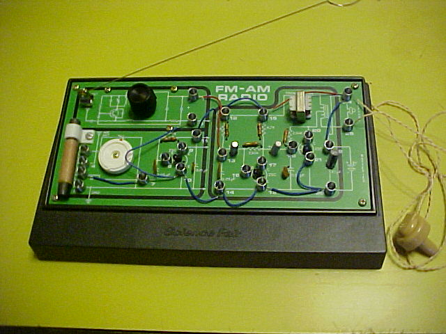
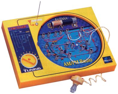
Assembled kit. The crystal earphone doesn't have good fidelity,
but is easy to drive. Hence, their popularity in cheap electronics kits
during the 1960's and 70's.
The kit I had bought was like new. I realised
about halfway through construction that it had actually been built before,
but had been ever so carefully dismantled and the components put back in
their little plastic bags.
Despite this kit, and other similar kinds,
claiming to "teach how radio works by building one", there is actually
no technical information in the manual. It merely mentions the amplification
available from the transistors and leaves it at that, thence proceeding
to the steps required to build up the set. It could actually mislead people
into thinking that all radios are essentially a chain of transistors amplifying
the weak signals from the aerial to sufficient strength for speaker operation.
While I don't expect a young constructor
to be given a lesson in super-regenerative theory, the instructions could
at least give more of an idea what is going on, and point out that the
typical commercially made radio receiver uses a more complex circuit (superhet)
operating with different principles.
The fact that FM receiver is already prebuilt
on a PCB just adds to the mystery. The only construction is for the very
simple AM tuned circuit and audio amplifier, which could be put together
by a trained monkey. Still, there is at least more construction involved
than the
Radio
Ace kit I reviewed.
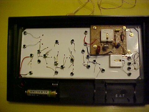
Under the chassis. Only one AA cell is present, as the kit requires
the other to be removed to turn off the radio. The PCB with the VHF circuitry
is at top right.
FM poor performance.
Having completed construction in a couple
of hours, I powered up with the kit wired for FM to be greeted by the usual
super regenerative hiss. Alas, performance was pathetic. This would have
to be the worst super regenerative receiver I can remember. In the middle
of metropolitan Sydney, only a few kilometres from most of the transmitters,
I could barely receive more than a few, and sound quality was appalling.
In fact, it was painful to listen to. Clearly, they had stuffed up with
design and modifications were in order, before I could use it. Even with
strong stations, the hiss was overpowering, and distortion was awful.
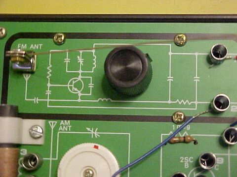
Closeup of circuit drawn on chassis for the VHF receiver. This is
what gives it away as being super regenerative. Seeing as they have done
so for the rest of the receiver, I don't understand why component values
are not shown. Incidentally, that aerial mounting is very fiddly to assemble.
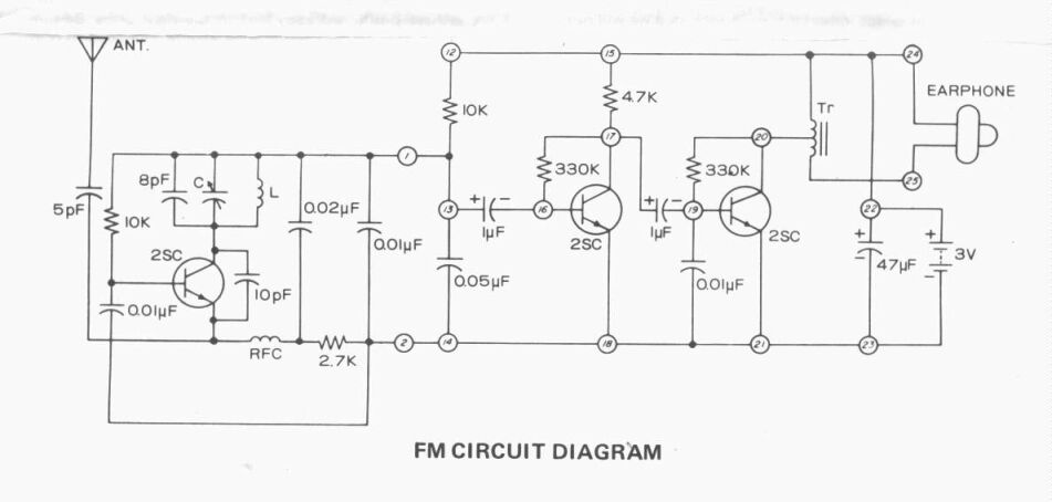
Circuit for kit wired in FM mode.
The Circuit:
It's a typical self quenched super-regenerator
built around one transistor. It's the sort of circuit you see in text books.
The transistor is connected as a Colpitts oscillator, with positive feedback
between collector and emitter. Base bias is provided by the 10K resistor.
The circuit is actually very similar to many FM wireless microphones. Squegging
occurs by virtue of the time constant formed by the 2.7K and .02uF. Quench
frequency is about 20Kc/s. Incoming signal is fed into the emitter, as
this is a low impedance point and aerial loading is less of a problem.
It could be said that the transistor is operating as a grounded base RF
amplifier in this way. Audio is developed across the 10K between terminals
12 and 13 and fed to the following two transistor class A amplifier of
conventional design. The output transformer is interesting as it's actually
a step up autotransformer. This works with the crystal earphone's high
impedance very well and provides extra volume for nothing. The various
capacitors help reduce RF and quench signals getting through and are an
aid to stability.
Modification to FM tuner.
Looking at the circuit, 10K to bias the
transistor seems a very low value. No wonder it oscillated so violently
and thus had poor sensitivity. Increasing this up to around 300K improved
things, but quench frequency was too low, giving an audible beat
with received signals. To raise this, I changed the .02uF to .0033uF, giving
a quench of about 30Kc/s.
However, now the receiver was producing
more audio output, the following two transistor amplifier was being overloaded,
in addition to the earphone volume being uncomfortably high. The properly
designed kit would have a volume control, but no such luxury was provided.
So, how to reduce the audio level? Simply shunting the audio output on
terminal 1 to ground with a low value resistor, in series with a capacitor
so as not to upset the DC conditions, worked quite well. I went one step
further, and cleaned up the quench signal somewhat too. By replacing the
.01uF between terminal 1 and 2 with a .1uF, much more of the quench signal
was shunted away before it got into the audio stages, and as most of the
high volume sounds were at the higher end of the audio spectrum, these
were heavily attenuated.
At last, the receiver was performing more
like how it should. Now the end was in sight, I tidied up a few other things.
The bias for the super regenerative detector was modified. The 10K went
back, as per the circuit, but I added a 22K from base to earth to reduce
the bias. This gives better DC stability than using a single high value
resistor. At home in the Blue Mountains, I was able to receive all the
stations expected from this kind of circuit, including C91.3 at Campbelltown,
with no aerial. However, reconnecting the aerial killed off the performance.
Obviously, there was too much loading. To fix this one, I removed the 5pF
and replaced it with a gimmick capacitor, which I adjusted to maximum capacitance
before reception was affected.
So, the receiver is useable now, but still
not as good as other super regenerative sets. This kind of self quenched
single transistor super-regenerative receiver never performs well from
my experience. If you do wish to build one, I recommend this
design where I did optimise everything as much as I could. It's a much
better performer, and at least has a regeneration control for optimum reception
across the band. If you want a transistor super regen set that really does
work properly, I suggest this
six transistor design.
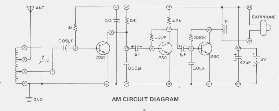
Circuit for kit when wired for Medium Wave AM reception.
AM Performance.
This actually did surprise me, and was
quite a contrast to the badly performing VHF circuit. Wired in AM mode,
I was able to receive the Sydney stations with no external aerial, at a
location on the Lower North Shore. At home in the Blue Mountains, reception
of course not as good, and an external aerial is required, although not
a very long one. Needless to say, the manual says nothing of how the AM
receiver works. Clearly, it is simply a transistor amplifier that is biassed
to be sufficiently non linear to detect AM. Biassing the first transistor
in the way they have is a very variable thing. There's no DC feedback unlike
the following two stages.
This means the transistor's operating
point is determined largely by its beta, or current gain, which of course
varies with individual transistors, even though they might have the same
type number. Different samples of this kit would therefore possibly perform
differently. The design has possibilities if you wanted to build a simple
local station AM receiver.
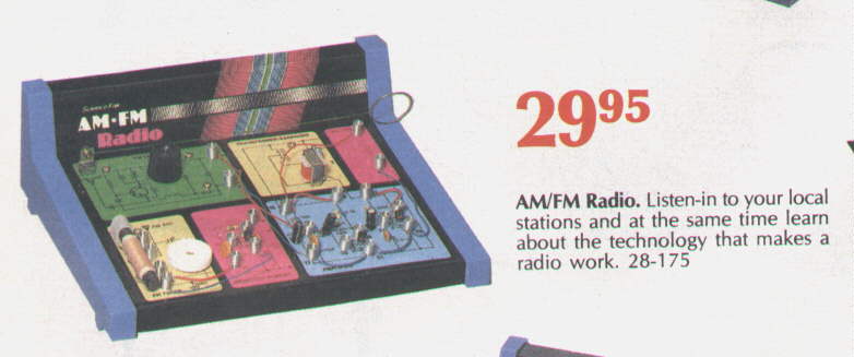
Later version of the kit that was still around when Tandy ceased
operations. It's built on a cardboard chassis so not as durable. This is
from the 1993 catalog, but had been sold since the mid 80's.
Other things that should have been
done.
The method of turning the receiver on
and off is verging on the impractical. The manual actually says to remove
one of the cells when not listening. It's quite difficult to get them out
of their holder under the chassis, and the removed cell can easily get
lost. A small slide switch should have been provided.
Also, the method of switching from AM
to FM is cumbersome. It involves simply reterminating various wires under
the springs. Eventually, the springs will pull out of the chassis and will
have to be pushed back in again. I'd expect the cardboard chassis set to
be worse in this regard. Again, some sort of switch should have been provided.
A volume control would have been nice, but not essential. One idea I thought
of was to replace the output transformer with one having an 8R secondary
so I could use proper headphones. However, this would detract from the
originality of the kit.
From the 1991 catalog, we see another of their super regenerative
kits; this one intended for listening to the aircraft band.

From 1979 was this 27MHz CB receiver. Although the scan is not clear,
it also is super-regenerative.
Conclusion.
I think this kit and its successor would
have left a lot of constructors disappointed with regards to FM. The crystal
earphone detracts from the quality of the sound. It's hard to believe I
listened to so much through that kind of earphone in my younger years,
but I had nothing else to compare it with so knew nothing better.
For those wanting to try this kit, be
prepared to modify it. Of course Tandy, and Radio Shack no longer sells
it, but there is another version currently available from the likes of
Elenco
as the MX-901F (FM only), or MX-901AF (AM & FM). Check the manuals
section of their site for the circuits. The kits are made by a company
called "Maxitronix", and have obviously copied Science Fair in that the
chassis they use is the same as that used by the Science Fair crystal radio
and two transistor radio kits. Interestingly, the AM section of the MX-901AF
uses a reflex receiver, but with only one diode, and no regeneration. I
would expect it to have superior performance to the Science Fair kits in
view of the reflexing.
MX-901AF is the replacement for the Science Fair kit and is available
from numerous suppliers. The performance is unknown, so be prepared to
modify it.