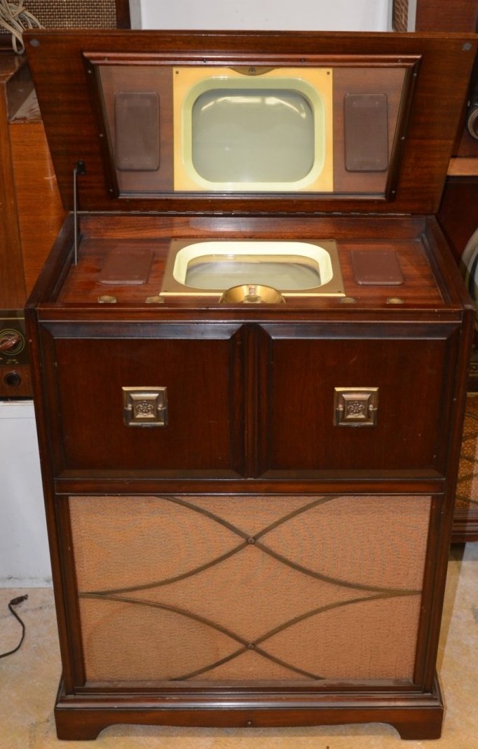
The set at the Eli Buk collection auction.
One way to get a mirror-in-the-lid set,
without paying the horrendous prices for a pre-war model, is to get a Sparton
4940TV. Fashion changes (and picture tube technology) saw the mirror-in-the-lid
design as obsolete by the 1940's, but nevertheless there were a few models
available post war, which were also produced in greater quantity. The best
known of these is the Sparton 4940TV, produced in 1949. Despite the antiquated
styling, the set internally is just like any other post-war U.S. made television
set, and even uses the ubiquitous 10BP4 picture tube. This in itself is
a good reason to get a post war model. Apart from sets using type 1802
CRT's, pre war sets have the worry of obscure and rare picture tubes, which
because of their shape are not easily substituted.
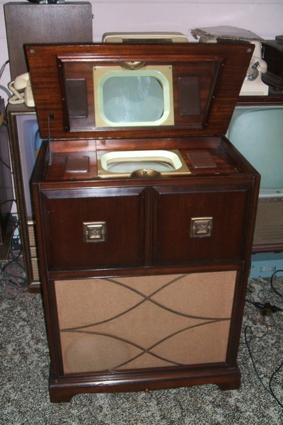
The 4940TV was also available in a larger
cabinet containing a radio and gramophone; the model 4900TV.
See my set operating here https://youtu.be/2rX8uyODfwg
The set at the Eli Buk collection auction.
Getting one to Australia.
I had known about the 4940TV for a few
years and learned that they were not uncommon, and not hugely expensive.
As someone who wanted a mirror-in-the-lid set, and with a particular fondness
for American styling, it was the obvious choice. In February 2016, I happened
to see one on the U.S. ebay for sale in Florida. Two things caught my attention.
Firstly, the set was in immaculate cosmetic condition, and secondly, but
more importantly, the seller was quite happy to ship internationally. The
seller was a dealer in vintage TV's and had apparently sent sets all over
the world. Just out of curiosity, I enquired about shipping to Australia,
not really thinking anything would come of it.
He came back and said US$650 for shipping
by air, and $50 for packing. The set was $800. So, US$1500 and I'd have
a round CRT mirror-in-the-lid set at last. I couldn't pass it up. The dealer
gave me references, one from a TV museum in Norway, which I followed up
and all seemed good.
I did an internet bank transfer and all
went OK. Pity about the exchange rate, because all up it cost about $2300
in Aussie dollars. However, what modern people pay for their "home theatre"
stuff is a lot more than this, and I'm getting something a lot better!
The payment was received by the seller
on the Monday afternoon, and the set was immediately sent out via a private
courier in Florida. It then came via Emirates in Dubai and much to my amazement,
I get a call on Friday afternoon saying it's in Sydney. To get a console
TV set from the U.S. to Australia in less than a week is pretty amazing.
You can tell you live in Australia when the payments don't end there...at
this end I had to pay a customs broker for clearance, and then when I picked
up the set at the Dnata freight terminal at Mascot, had to pay a "handling
fee"; about $150 for a bloke to put it on a forklift, drive it 20m and
put in the back of my ute. But at last it was here and I couldn't wait
to get out of Sydney and back home to unload it.
It was really well packed. The set was
wrapped in plastic and then layers of styrofoam insulation and finally
cardboard outer covering. It was all attached to a wooden pallet. Inside
the set, foam cushion had been packed in to protect the CRT and other parts.
Even the decorative cabinet handles had been covered in tape. I can't imagine
a more professional job. The set had arrived in perfect condition.
One thing I had noticed is that most of
the valves were unusually clean. When I enquired about the history of the
set, I was told it was part of the Eli Buk collection, and had been auctioned
off after his death. Looking at it in the auction photos then, the valves
are quite dusty, so it would seem that the seller had cleaned them.
You can see the set at the auction here.
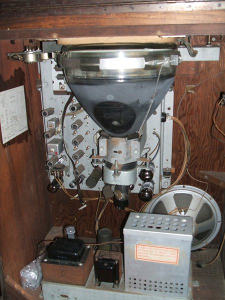
Inside the cabinet. The valves without shields had been cleaned.
CRT is a Hytron 10BP4. The B+ and EHT power supply chassis is separate
to the main TV chassis.
Restoration commences.
It was not until the end of 2016 that
I actually started work on the set. It was interesting to see that apart
from just four capacitors, everything was original. Not bad for a set made
68 years ago. True, we don't know when it was taken out of use, but for
an old valve set that's still very good. Curious, I decided to see if the
electrolytic condensers would reform. With a variac feeding the 240-115V
step-down transformer, I tried those on the power supply chassis first.
With the voltmeter connected across the B+, I knew it was time to raise
the input voltage a bit further once the B+ stopped rising. Over couple
of hours the capacitors seemed quite OK and could even light a 15W bulb
for a couple of seconds. This indicated they had a decent amount of capacitance.
There was no warmth from them which indicated the leakage was also low.
Chances were the electros in the main chassis would also be good.
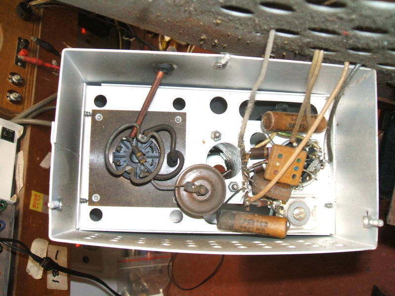
Power Supply Chassis.
The power supply chassis is simple with
a conventional transformer and 5U4 rectifier. Of course, being American
and post war, the supply is designed for 117V operation. Hence the need
to use a step-down transformer for Australian 240V mains. Also on this
chassis is the RF EHT power supply. Interestingly, of all valves they could
have chosen, a 6SN7 with the triodes paralleled is the oscillator. Normally,
valves like 6V6, 6Y6, or 6L6 are typical for this application. The RF transformer
itself is quite conventional and similar to those used in smaller electrostatic
sets. The rectifier is a 1B3 (or 8016 if you prefer the pre RMA type number).
Output is 10kV.
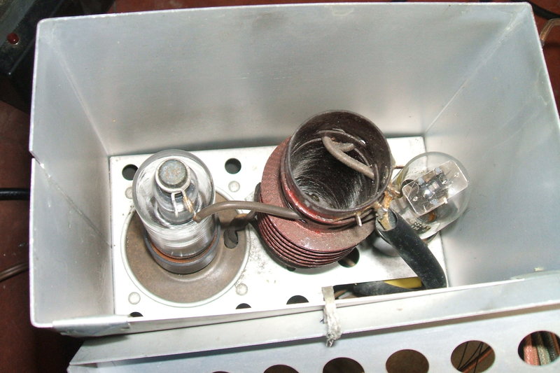
Inside the RF EHT power supply.
Main Chassis.
Turning now to the main chassis, the first
thing to do was replace most of the paper condensers. A quick check showed
none of the resistors had drifted. I wasn't surprised in view of a similarly
aged 7" Admiral I once restored about ten years previously. It seems the
Americans could make resistors that didn't drift. It's a pity we did not
have the same manufacturer in Australia, because high resistors in local
sets are just as much of a problem as leaky capacitors. Only having to
replace the paper condensers would speed up the restoration. I had it all
done over about three days. It was nice to see component leads not wrapped
around the tags multiple times, and this made replacement easy.
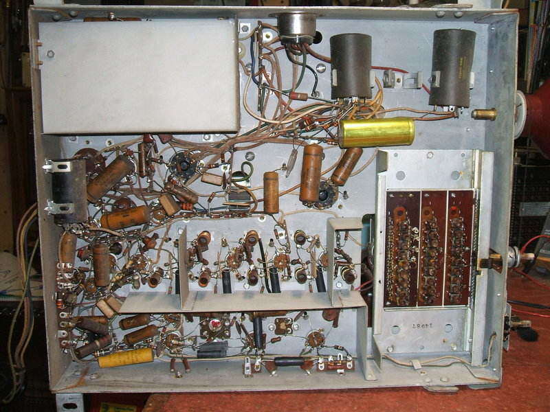
Chassis in original condition. The gold coloured electrolytic at
the top right and three other smaller capacitors in the line oscillator
were the only components changed in the set's prior history.
To reform the electrolytics on the main chassis, I used a separate power supply; my BWD 215. I did this because I didn't want to run the valve heaters which would cause extra B+ current draw, and thus be misleading in terms of leakage current. Again, it was a case of raising the voltage in steps each time the leakage current dropped off.
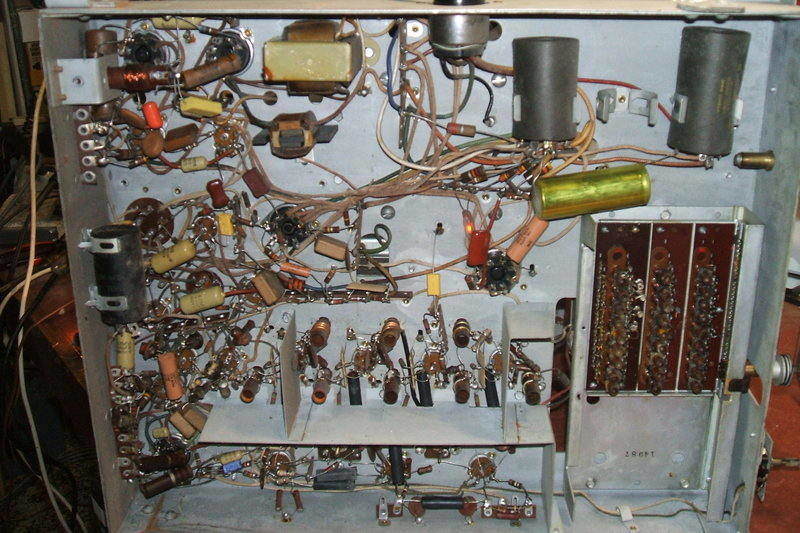
Paper caps have been replaced, except where leakage is not of concern.
Astute readers will notice the neon lamp near the centre is illuminated.
Now the set was ready to be powered up. Initially there was no light on the screen because the ion trap was wrongly set, and also because the 15uF electrolytic (C6) associated with the brightness control needed further reforming. Soon, there was quite a good raster, and most importantly, brightness and focus were good, indicating an excellent 10BP4.
U.S. vs. Australian Television Standards.
At this point it's worth briefly mentioning
the use of U.S. made TV sets in Australia. The difference in mains voltage
is easily dealt with using a commonly available transformer. However, the
transmission standards are different, but still close enough. Both systems
use negative modulation, FM sound and operate in the VHF band. For 525
line operation in the U.S., the line oscillator operates at 15,750c/s (15,734
c/s for colour transmissions), and the frame oscillator operates at 60c/s
(59.94c/s for colour). For 625 line operation in Australia, the line oscillator
operates at 15,625c/s. This is so close that usually not even the line
hold control needs to be adjusted. However, the frame oscillator needs
to operate at 50c/s. This simply is a matter of adjustment of the frame
hold control. To compensate for the lower field frequency, the height control
then needs to be readjusted. Because the height actually needs to be reduced
at the lower frequency, there is no problem in it not having enough adjustment.
So far, all that is needed to produce
a 625 line picture on a 525 line set is simply to reset the frame hold
and readjust the height (and possibly the linearity).
To receive an off air picture, the differences
in channel frequencies also have to be accommodated. It so happened that
prior to the analog switch off (Dec 3rd 2013), the Australian capital city
channels were receivable by an American tuner with some adjustment of the
local oscillator.
The stumbling block with using American
sets in Australia comes down to the difference in the video-sound spacing.
In the U.S., it's 4.5Mc/s, but in Australia with the wider bandwidth video
signal, it's 5.5Mc/s.
In order to receive the sound it is necessary
to retune the sound IF to the higher frequency. Sometimes there is enough
adjustment, other times the tuning capacitors associated with the IF and
detector coils have to be reduced to get the frequency high enough. Once
tuned, it was quite easy to use an American set in Australia with the off
air channels. It is true that the video IF should be realigned in view
of adjacent channel traps and so on, but in practice it usually worked
quite well left as is.
However, that is all now history as there
are no longer off air transmissions receivable by old sets. Now, the only
analog signals come from devices that produce base band audio and video,
such as digital tuners, VCR's and DVD players. It therefore makes sense
to simply modulate these sources using a system M (U.S. standard) modulator.
This will provide the correct video-sound spacing, as well as be compatible
with the set's tuner. Invariably, the output of these modulators is on
the U.S. channels 3 or 4.
Thus, no RF or IF realignment needs to
be done. System M modulators are easily obtainable from the U.S. ebay,
and inexpensive. In fact, the postage will cost more!
This is the approach I took with the Sparton. Effectively, the set is now being fed with a system N signal. That is, 625 line 50 field, but with 4.5Mc/s video-sound spacing. This system is actually used in parts of South America.
First Pictures - No Sound.
My first attempts in feeding a picture
into the set were disappointing. There seemed to be a lot of ringing in
the picture and there was no sound. At one end of fine tuning adjustment
a reasonable picture could be obtained, but still no sound. At the other
extreme, a weak sound could be heard, but the picture was well out of tune.
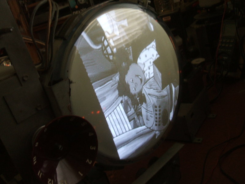
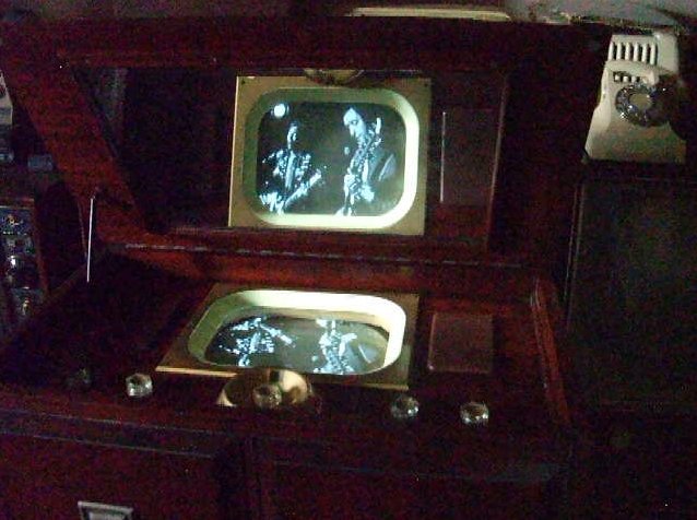
One of the first pictures. A non technical viewer might find it
acceptable, but there was an obvious problem with the alignment.
First thing I decided to check was the
sound IF alignment, seeing that a reasonable picture could be obtained.
This was only slightly out and was easy to touch up. However, the problem
still remained.
Given this set uses a split-sound IF,
the absence of sound could now only mean the tuner's local oscillator was
off frequency. Indeed I was able to confirm that all channels had drifted
up by about 2Mc/s.
Trying another 6C4 did not correct this,
so I can only assume one of the capacitors in the 6C4 circuit has drifted
slightly. There was not enough fine tuning adjustment. Chances are if I
had started replacing capacitors in the tuner, I'd have to realign it anyway,
so I simply readjusted the local oscillator slugs for channels 3 and 4
(the only channels I'll ever use as these are the standard U.S. modulator
channels).
Now, we had sound. Problem is the picture
was now so off tune as to be unwatchable. There was some buzz in the sound,
and I suspected the 5uF electrolytic across the ratio detector output was
largely responsible. If this capacitor fails, the limiting feature stops
working, and there is no AM rejection. Replacing the capacitor improved
things somewhat.
IF Re-alignment.
Obviously, the video IF alignment is what
was really out of adjustment to start with. At first I readjusted the IF
coil cores to the spot frequencies listed in the service manual. Alas,
the picture was even worse. I had also noticed one of the coils (the 22.4Mc/s
mixer plate load) didn't seem to peak properly. I went over this procedure
a couple of times but without improvement. It was clear I'd have to see
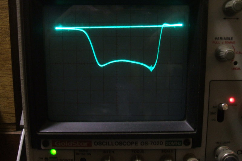
what was going on by using a sweep generator. Not surprisingly, the response
curve looked pretty awful.
The coil that wouldn't peak had me curious.
By placing a ferrite slug into the coil former, I could make the curve
change so the coil must have been doing something. Each stage of IF amplification,
from the mixer plate onwards is electrically much the same. All the other
coils had a definite peak.
To cut a long story short, I could peak
the coil at 23.5Mc/s but no lower. It needed to be 22.4Mc/s. It seemed
that there was too not enough capacitance. The IF coils are not resonated
with an actual capacitor as such, but by stray capacitance present in the
chassis wiring and between the valve electrodes. Because it was easy to
try, I replaced the 6AG5 mixer, but this didn't do anything. There was
the 270pF in series with the next stage so tried that. Still no joy. One
thing I had overlooked was the 27.75Mc/s trap coil in series with the mixer
plate, but as it had peaked OK and was on a much different frequency I
had discounted it as having any effect. As I was running out of options,
I bridged it out with a clip lead and tried again. This time the 22.4Mc/s
coil peaked! So what was going on? Well, the 27.75Mc/s coil peaked too,
so nothing was making sense. That is, until I thought about where it peaked...
tuned circuits have two peaks; an inner and an outer. I'd tuned it for
the inner peak. When I realised this, (and the manual does point it out)
and peaked it on the outer, both it and the 22.4Mc/s coil were correctly
tuned.
The picture was still unwatchable and the
response curve totally incorrect. As peaking each of the coils to their
supposed correct resonant frequency had not achieved anything, I decided
to ignore that method of alignment, and simply adjust for the correct curve.
For one thing, the bandwidth was too narrow, and I sensed the last stage
was actually oscillating. The curve would vary wildly just by putting my
hand near the last IF coil without actually touching it.
Sure enough, tuning for a broader bandwidth
brought the gain down and everything was stable. It didn't take long to
peak things up with the markers in the correct places.
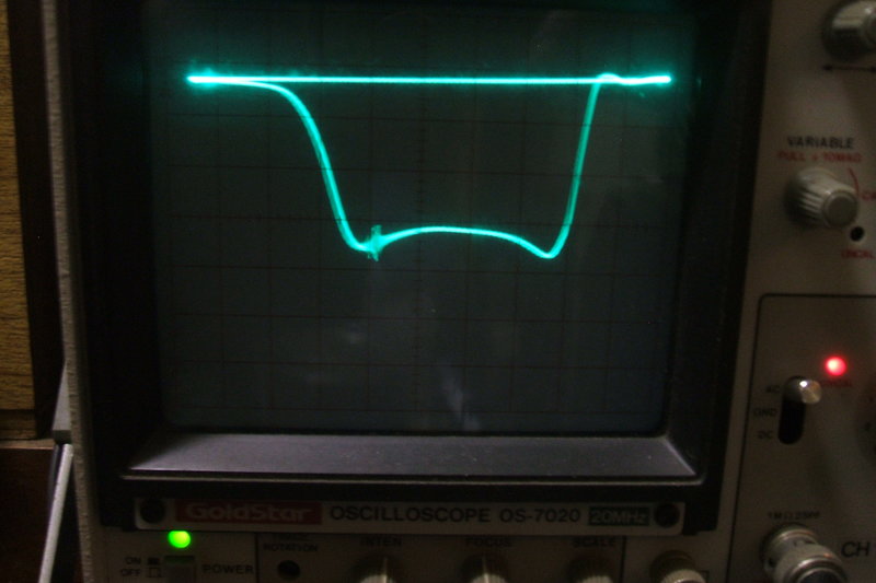

From left to right, markers at 22.7Mc/s, 25.5Mc/s, and 26.5Mc/s
(barely visible half way up the left side of the waveform).
Much joy at last when I fed in the RF from
the modulator and got a good picture, and even the sound was correctly
tuned!
Out of curiosity, I decided to see what
the "correct" spot frequencies were for the IF coils, and did indeed find
them slightly different to those specified, particularly for the last two
coils.
Retrace Blanking.
One thing that had been evident all along
when looking at the picture was the presence of retrace lines. It seems
that early sets like this rely (or try to rely) on the video signal alone
to blank the screen during the field blanking interval, because they do
not contain any blanking circuitry. In theory, it should work with a DC
coupled or DC restored video stage; the latter being present in this set.
In reality it is not completely effective, and blanking effectiveness depends
on brightness, contrast, and picture content.
It is however, an easy matter to arrange
for proper blanking. All that's needed is a pulse of sufficient amplitude
to cut the CRT off during the field blanking interval. Either the grid
needs to go negative, or the cathode needs to go positive. So that the
blanking circuit does not interfere with the video signal, it needs to
be injected into the electrode that does not modulate the CRT with
video signal.
In the case of the Sparton, the video
is fed into the grid. This means our blanking circuit needs to inject a
positive pulse into the cathode.
As it is, the cathode is fed via the brightness
voltage and decoupled by a 15uF capacitor. The cathode needs to be decoupled
from this capacitor by a resistor; no more than about 100K. Then we need
a suitably timed positive pulse. Conveniently, this is available at the
6V6 frame output valve plate. All that now needs to be done is to connect
this pulse via a DC isolating capacitor and voltage dividing resistor to
the 10BP4 cathode.
![]()
Blanking modification for the Sparton.
The circuit worked first go, and with an
optimisation of components, the decoupling resistor was 33K, the voltage
dividing resistor 1M, and the capacitor .01uF. In view of the high peak
voltage, the 1M needs to be 1W, and the capacitor at least 1000V.
I used a 3kV ceramic. Too much blanking voltage will blank out the top
part of the picture, and too little, will of course, leave visible retrace
lines. A three lug tagstrip was mounted just next to the 6V6 for the additional
parts.
At last, the set was ready to go back
into the cabinet.
Lid Switch.
The set is turned on and off by raising
or lowering the cabinet lid. I had noticed that the mechanism was either
out of alignment or missing something because the switch itself did not
move with the lid.
A closer look seemed to indicate a pivot
might be missing. I had an aluminium spacer which looked like it would
make a good substitute, and suitably drilled, it fitted perfectly. The
switch now reliably changed positions as the lid was raised or lowered.
Centering Adjustments.
Because of the Earth's magnetic field,
it was pointless to check the centering adjustments with the chassis on
the bench while the picture tube was horizontal. The adjustment works on
the basis of pivoting the focus coil around its axis by means of spring
loaded screws. That is to say, the focus coil electromagnet also functions
as the centering magnet.
For the test pattern I used my Philips
PM5544 .jpg file played in the DVX digital box. I'm not sure if something
around the picture tube has residual magnetism, but I could barely get
enough adjustment.
Nevertheless, the end result is good.
The deflection coils also needed a slight adjustment to the tilt.
Tuner.
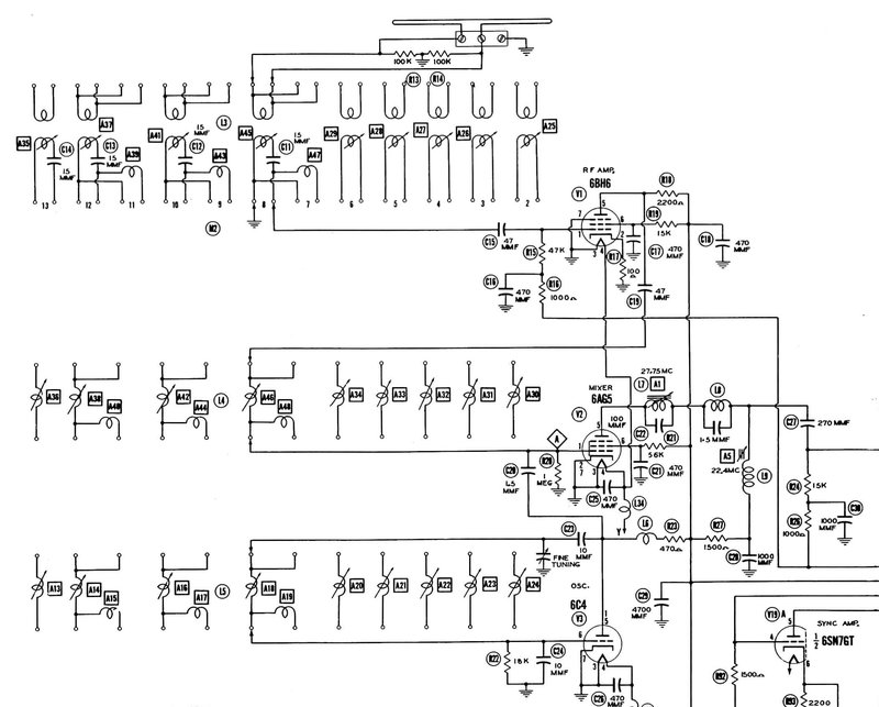
This uses a 6BH6 pentode as an RF amplifier.
Input is the usual balanced 300 ohm impedance. Pentodes had become obsolete
for this purpose by the mid 1950's when the lower noise cascode triode
circuit had taken over. The mixer is a 6AG5 pentode, and the local oscillator
is a 6C4. By the mid 1950's separate mixer and oscillator valves had been
replaced by a single triode pentode specifically designed for the purpose.
Well known types include the 6U8 and 6BL8.
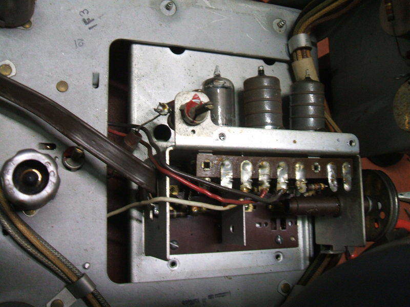
Top of tuner shows RF, oscillator, and mixer valves, from left to
right. The pulley at the front is for fine tuning via a dial cord mechanism.
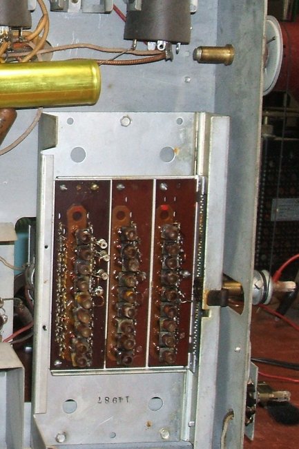
Underneath, the rack and pinion can be seen. From left to right, the coils
are RF, oscillator, and mixer in their separate rows.
The mechanical construction of the tuner is quite interesting. Each set of coils for each channel is independent from the others, so electrically it works like a turret tuner, but instead of separate biscuits, all the coils are mounted on insulating strips which move back and forth over the contacts by means of a rack and pinion. The 4940TV is fitted with U.S. channels 2 to 13, but there is space where the channel 1 coils were fitted when this tuner was used with an earlier model. The IF is 26.25Mc/s for video and 21.75 for sound.
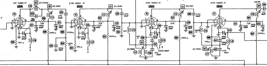
Video IF amplifier.
Four stages using 6BH6 valves are used.
Each stage is tuned to a slightly different frequency so that the overall
bandwidth is adequate for the video signal. In other words, stagger tuning.
Traps are provided for sound and adjacent channel rejection. The sound
IF is taken from the cathode of the third 6BH6 and this coil also functions
as a sound trap.
The Split Sound and Intercarrier
systems.
This is a split sound set, so unlike modern
intercarrier designs, the sound IF is that which comes out of the tuner;
in this case 21.75Mc/s. Modern sets use the difference between the video
and sound frequencies as the IF. This is known as the intercarrier system,
and was first implemented around 1949. In effect, the video detector acts
as a mixer. The video IF signal performs as the local oscillator, and therefore
the sound IF output is simply the difference between the vision and sound
carriers. In the case of the U.S. system, this is 4.5Mc/s. It can be seen
for this to work that there must be a video signal present, otherwise the
sound carrier has nothing to mix with. Therefore, one stipulation with
the transmitters (or RF modulators) is that peak white does not cut off
the video carrier. If this happens, a prominent buzz at the frame scanning
rate is heard in the sound. Of course, the intercarrier system can only
work where the sound is FM. Television systems that use AM sound are unsuitable
because the video signal is AM also and would modulate the detected audio.
The advantage of the intercarrier system
is that it renders set tuning non critical for the user. Furthermore it
makes local oscillator construction less critical in terms of frequency
drift. The sound IF is always perfectly in tune because it is set by the
vision and sound carrier oscillators at the transmitter, which are at the
least crystal based. With split sound sets, the set is tuned for best sound,
and hopefully this coincides with best picture, if the set alignment is
in order. However, as the FM detector must be accurately tuned to avoid
distorted sound, it can be seen that any drift will require use of the
fine tuning control. This becomes more problematic with higher frequency
channels of course.
For the intercarrier system to be successful,
good attention must be paid to set design, and anything that distorts the
video signal such as overloaded video IF or detector stages can lead to
annoying buzz in the sound. Poor AM rejection in the sound IF stages and
detector can also lead to problems.
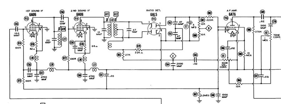
The Sparton sound IF and Audio stages.
There are two sound IF amplifiers using
6AU6 valves. Apart from the power supply which will be discussed later,
the circuit is conventional. However, something seldom seen in an FM sound
IF amplifier is the application of AGC. The amplified 21.75Mc/s signal
feeds a ratio detector using the ubiquitous 6AL5 double diode valve. Ratio
detectors have inherent AM rejection which is why there is no separate
limiting stage. The negative going output from the 6AL5 provides the AGC
voltage which controls the first 6AU6. The AGC is delayed by means of a
2.2M resistor which is effectively connected to +150V.
The 6AT6 diodes prevent the AGC line going
positive when there is no signal and thus causing the first 6AU6 to draw
excessive current. Delayed AGC circuits are used to prevent loss of gain
with weak signals. Here, the signal strength has to be strong enough to
overcome the current flowing through R87 (2.2M) before the 6AU6 (V13)
gain is throttled back. If the AGC is not delayed, there will be a negative
voltage produced from atmospheric and circuit induced noise. Thus the 6AU6
would be throttled back already with weak signals which is just when it
needs to operate at full gain.
From the ratio detector, the audio signal
passes through the volume control potentiometer and into the triode of
a 6AT6, and thence a 6V6 beam tetrode in the usual way. There is a top
cut tone control in the 6AT6 plate circuit using a 1M pot and 5100pF capacitor.
The volume control has a loudness circuit by means of a tapping on the
volume control and a .03uF capacitor. This enhances the bass response at
low volume. The loudness control is taken out of circuit when the tone
is at the maximum treble setting. Here, the .03uF (C67) is shorted out.
What is surprising is that despite this
extra attention to the tone control, the 6V6 is operating without negative
feedback. While I have not attempted to measure the performance of the
audio stage, it could simply be that the tone control has been designed
to accommodate the frequency response of the 6V6 operating with no feedback.
That still doesn't reduce distortion, however.
Video Detectors and Amplifiers.
Another unusual aspect of this set is
that there are two separate video detectors which feed two independent
video amplifier stages. Starting with the more conventional stage, there
is a 1N34 diode for the detector, which then feeds the demodulated video
signal into a 6AU6 operating as the first video amplifier. This then feeds
a 6AK6 as the video output. Two video stages are required when fed from
a negative going signal to retain the correct video polarity when the signal
is fed into the picture tube grid. This circuit is completely conventional,
and has the usual compensating chokes in the plate circuits of each valve.
The contrast control is a 3K cathode rheostat for the 6AU6 and provides
variable degeneration in the usual way. It is frequency compensated with
a choke and capacitor to retain picture sharpness as the gain is reduced.
With the exception of the video detector to 6AU6 grid, the video amplifier
is all AC coupled, and this includes the connection to the picture tube
grid. However, there is DC restoration applied at this point.
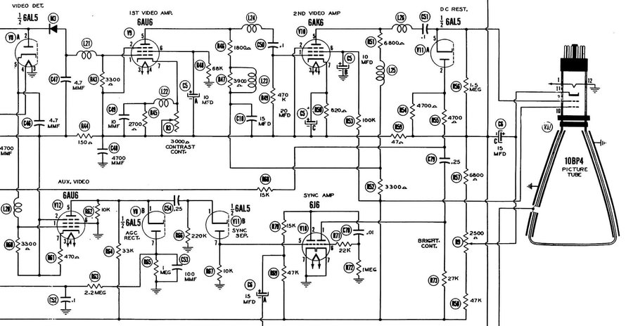
The second video detector is half of a 6AL5, and interestingly provides an inverted video signal. This feeds an "Auxiliary Video" amplifier consisting of a 6AU6. Its purpose is solely to drive the AGC and sync circuits. It is curious why the other half of the 6AL5 was not used instead of the crystal diode for the main video amplifier. As the 6AU6 is concerned with sync information only, it does not need the frequency compensation required as when driving a picture tube.
Video AGC.
This operates using a peak level detector
using one half of a 6AL5 diode, fed from the auxiliary video amplifier.
Here, C53 (100mmF) charges to a negative voltage representative of the
sync pulse tips. The sync pulse level, of course, remains constant regardless
of the picture information, so is an ideal reference for AGC circuits.
R63 (2.2M) and C52 (.1uF) filter out the video signal, creating a clean
DC voltage to control the RF amplifier, and first and second video IF amplifier
valves.
Sync Separator & Amplifier.
Here's another interesting piece of design;
a diode sync separator! Often seen in pre-war sets, it soon faded into
obscurity, to be replaced with triodes or pentodes operating with no bias
and low plate and screen voltages. Yet, the technique is perfectly logical
and viable. In fact I used a diode sync separator for my 2"
TV set.
The video signal is fed into another 6AL5
diode much like the AGC peak detector. The coupling capacitor, C54 (.25uF)
charges to the peak video voltage through the diode and R67 (10K). Thus,
the 10K has a voltage across it proportional to the .25uF's charge current.
Because of the time constant of the .25uF and R66 (220K), capacitor charge
current only flows at the peak voltage, in other words, where the sync
pulses are. Thus, at the 6AL5 plate we have a clipped video signal with
only the sync pulses present.
The recovered sync pulses are then fed
into a two stage amplifier based around a 6J6 twin triode. It's an interesting
choice of valve given that it was designed for VHF work, but there's no
reason not to use it. Both triodes operate with no bias and therefore
provide further clipping of the sync pulses to ensure no picture signal
remains. The amplified and clean pulses emerge from pin 1 of the 6J6.
There is a connection between the sync
amplifier and the DC restorer which is not entirely clear as to its purpose.
It is suggestive of a blanking circuit in which the CRT grid is driven
more negatively during the sync pulses.
DC Restorer.
Common in U.S. designed sets until the
1950's was the diode DC restorer. If the video signal remains AC coupled
all the way to the picture tube, the average brightness remains the same
regardless of scene content. It is not possible for the viewed picture
to show a true black level. It is certainly cheaper and technically more
convenient to make television sets with AC coupled video amplifiers, and
many sets have been made this way. The typical non technical viewer is
oblivious to the loss of true black level, being distracted by the program
content.
One can DC couple the whole system from
the video detector right through to the picture tube, but any changes in
operating characteristics of the video amplifier will alter the black level,
as will signal strength changes, unless the AGC circuit is particularly
good (i.e. complicated/more costly). Alternatively, the video circuit can
remain AC coupled, but the DC component restored at the picture tube.
Given that the sync pulses remain fixed
to the black level, the operating point of the picture tube can be referenced
to the sync pulse tips. In a typical diode DC restorer circuit, including
the Sparton, the minimum picture tube grid voltage is always that of the
peak sync pulse voltage, as obtained by C51 (.1uF) charging through V11A.
Frame Timebase.
This part of the set is largely conventional,
and would not look out of place in sets made 10 years later.
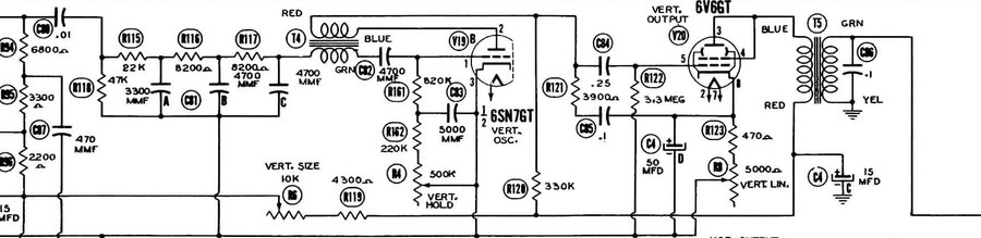
A blocking oscillator is used based around
a 6SN7 triode which drives a triode connected 6V6 in the usual manner.
Sync pulses are fed in via the low pass filter (integrator) consisting
of R115-R117 and their associated capacitors. This filters out the higher
frequency line sync pulses.
Triode frame output stages are much easier
to obtain good linearity from than those using pentodes, which require
complex feedback networks. The trade-off is the triode stage is less efficient,
but this is not important with low angle deflection picture tubes like
the 10BP4. In the 1950's purpose designed triodes were developed for frame
output stages, such as the 12BH7, 6S4, and 6CM7.
There are two interesting departures from
'modern' practice in this circuit. Firstly, the oscillator plate voltage
comes from the ordinary B+ that drives the output stage rather than a higher
'boost' voltage.
Secondly, the method of height control
is simply a 10K wirewound rheostat in series with the B+ to both the oscillator
and output stages.
Line Timebase.
Of all the sections of the set, this is
undoubtedly the most unusual. Like the diode sync separator, the line output
stage in the Sparton is a throw-back to pre-war methods.
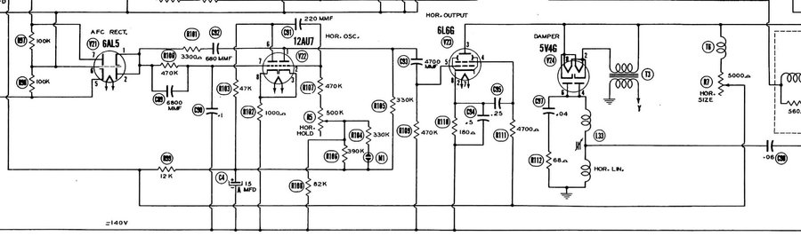
The AFC circuit and line oscillator are actually quite conventional and not out of place in a modern set. The only exception is there is no tuned circuit in the line oscillator plate circuit. Such a coil/capacitor combination is tuned to the line frequency and termed a "stability" or "sine wave" coil, and basically improves the frequency stability of the stage. Evidently, with other prewar aspects evident in the set's design, they thought a direct sync line oscillator might be taking things too far, and so AFC using a 6AL5 is included. This compares the frequency and phase of the line oscillator to the incoming sync pulses. A positive or negative going correction voltage is developed across C90 (.1uF) which lowers or raises the oscillation frequency until it is the same as the sync pulses. A rather strange inclusion is a neon lamp (M1), which supposedly functions as a regulator for the line oscillator. It is unclear how it can regulate effectively when there is a 330K resistor in series with it.
Turning now to the line output stage, we
have an ordinary audio output valve, a 6L6, functioning in this position.
By 1949, a 'proper' line output valve, the 6BG6, had been developed and
was widespread.
Valves like 6L6 and 807 were certainly
not uncommon in prewar electromagnetically deflected sets in this position.
The use of a 5V4 rectifier valve as a damper diode is not however unusual
in post-war sets. The 5V4 was popular for this application because it has
a suitably low plate resistance. However, it does require a well insulated
5V heater winding either on the normal power transformer, or as here, a
separate 6.3V to 5V isolating transformer with low inter winding capacity.
By the mid 1950's, valve technology had produced a diode with low plate
resistance but with a well insulated cathode that could withstand the necessary
high voltage peaks and run off the normal 6.3V heater circuit. This was
the beginning of the 6AX4 and related types.
One obvious omission is a line output transformer.
There isn't one. Instead, the line deflection coils are choke coupled to
the 6L6 plate by T6. The width control is simply a 5K rheostat in series
with this.
Because of the negative and positive B+
power supply distribution in this set, not all the 6L6 plate current comes
via T6 as first thought. Most actually comes via the 5V4, so the 5K rheostat
is not as stressed as it may first appear.
Power Supplies.
Not uncommon for the time is an RF EHT
supply. The normal B+ power supply is conventional with a transformer and
5U4 rectifier.
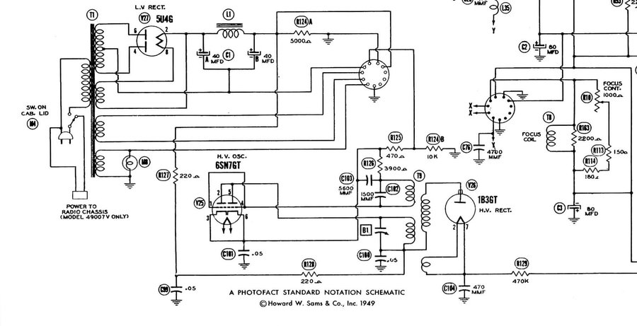
The set operates with a split power supply.
That is, both negative and positive rails are used. Parts which require
the most voltage are connected between the positive and negative rails,
whereas sections like the IF stages are connected between either the positive
rail and earth, or the negative rail and earth. Going back to the sound
IF stage, it will be noticed that the plates and screens are connected
to earth. This is because the cathodes are fed from the B- rail. The B-
is -140V and the B+ is 180V. This technique allows for efficient voltage
distribution. For example, it is wasteful to operate a 180V IF amplifier
off a 320V supply via a resistor when other sections can be used as a 'dropper
resistor' instead.
The entire set's current also flows through
the focus coil. This has a variable shunt across it to set the exact coil
current for optimum focus.
I am not keen on the absence of a fuse
or circuit breaker and may add one.
While the use of an RF EHT supply was not unusual in 1949, the use of a 6SN7 as its oscillator does tend to stand out. Both triodes are paralleled. The circuit is conventional otherwise, and I discuss RF EHT supplies in more detail here. Output is 10kV.
Of course, for Australian use, it is necessary to use a 240V to 120V step-down transformer. I use one of my 300VA toroidals for this set.