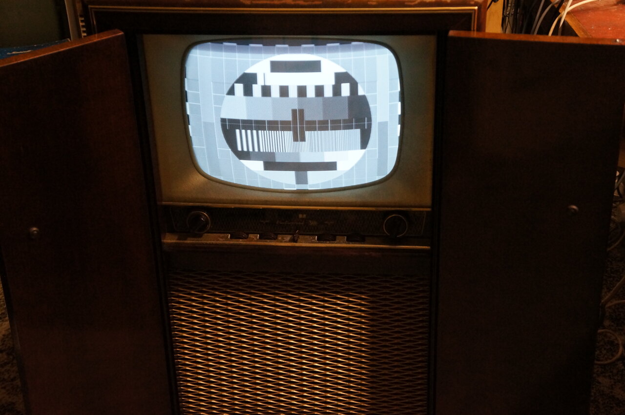
Imported SABA T544 installed in a locally assembled console cabinet.
Imported SABA T544 installed in a locally assembled console cabinet.
When television commenced in Australia during 1956, most sets were locally built. They generally fell into one of two types; those adapted from U.S. design, and those from European design. The Australian manufacturers marketing these sets adapted the designs for local conditions to a lesser or greater degree. In one instance, Admiral went so far as to market what was essentially a U.S. model complete with the U.S. video IF. All that was done was to modify the tuner for the local channels, and provide the power transformer with a 240V primary. At the other end, AWA adapted RCA designs from the U.S., and Philips naturally adapted European designs, but with a greater local input being done in their design laboratories.
A few German sets were imported, since
Germany was already using the 625 line system that Australia adopted. Graetz,
Nordmende and Grundig were probably the most common of these, and from
what I gather they were sold more so in Melbourne than Sydney.
However, one Sydney based company, Electrosound,
imported a SABA chassis and installed it in a locally made cabinet. It
is the most prevalent of the German imports.
Electrosound was probably best known for
their radiograms, and was also importing SABA counterparts because they
included FM receivers. From 1947 to 1961, Australia did have FM broadcasting,
but because of the 'experimental' nature of the service, very few local
manufacturers made receivers.
I was already aware of SABA, since a school
friend had one of their colour sets in the late 1970's.
The SABA set to be described is a 17" 70
degree model, T544. In Germany, this was a table model set. Electrosound
installed it in a console cabinet, and provided it with the model number
E544. Being typical of European design, the SABA is live chassis with series
heaters. That's something that Australian technicians loathed, and to placate
them, an isolating transformer was mounted in the Electrosound cabinet.
Additionally, the tuner was provided with all 10 Australian VHF channels,
and with a minor modification, adapted for 240V instead of 220V mains.
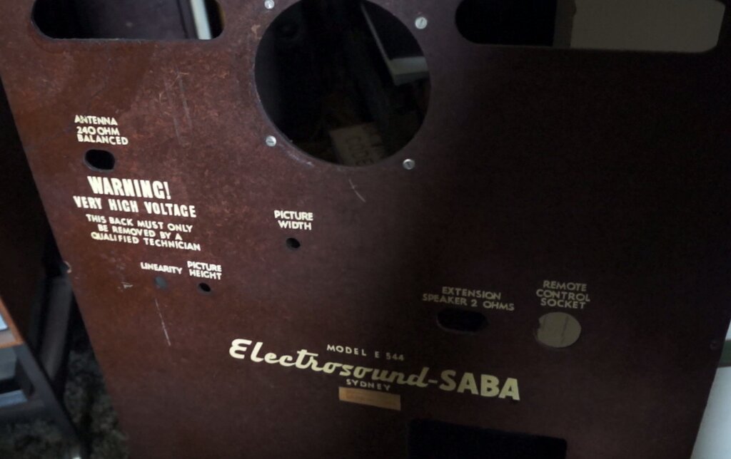
The glass front panel with its "Electrosound" logo and English names for
the controls, was also obviously made in the SABA factory. The speaker
is an Australian made 12" Rola; a type that Electrosound was already using
in their radiograms. The transformer is a Henderson, a common brand which
Electrosound also used.
The set came to me via an HRSA member
who knew I liked series heater TV sets. Seeing that it had been recapped,
I powered it up but alas nothing more than the valve heaters lit up.
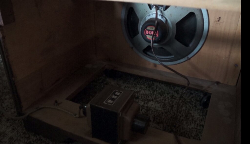
12" Rola speaker gives far better sound than that of the original
table model.
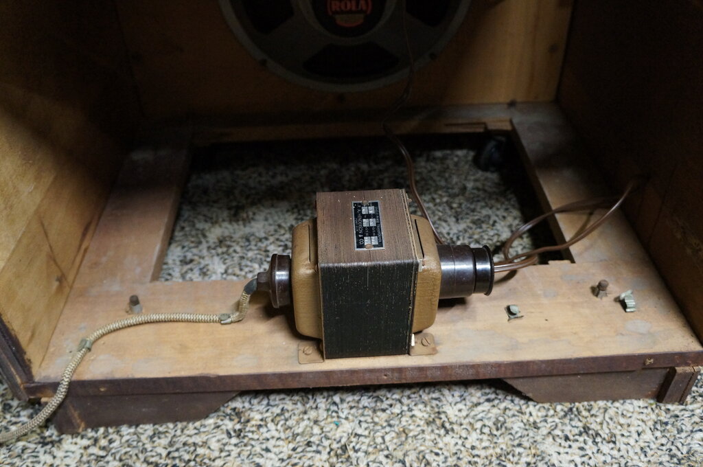
Isolating transformer. Output is a two pin socket.
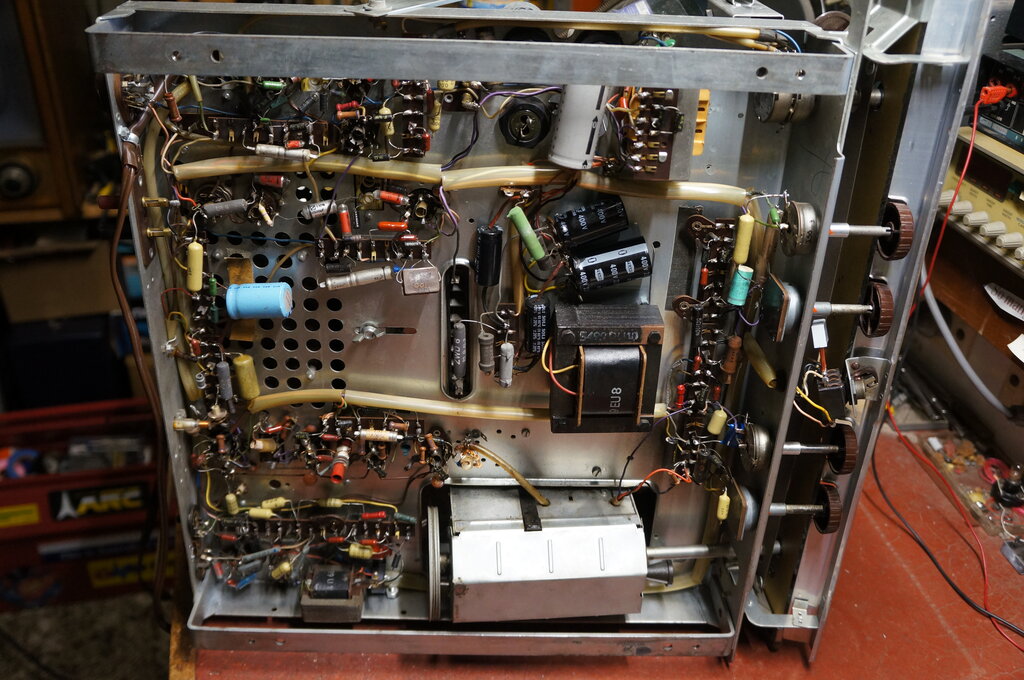
One of the best sets I've worked on for serviceability.
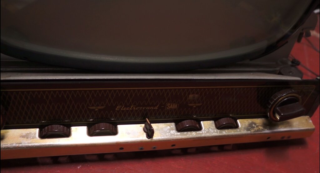
Glass front panel made to Electrosound's specifications. On off
switch toggle is actually a removable key.
A few sets of the era offered remote control, and the SABA is one of these. Alas, it only provides volume and brightness control. The remote control plugs into a 9 pin valve socket at the rear of the chassis. There are also sockets for an extension speaker. These, along with the aerial input are 4mm banana sockets.
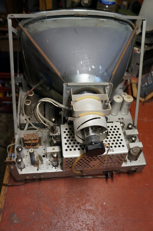
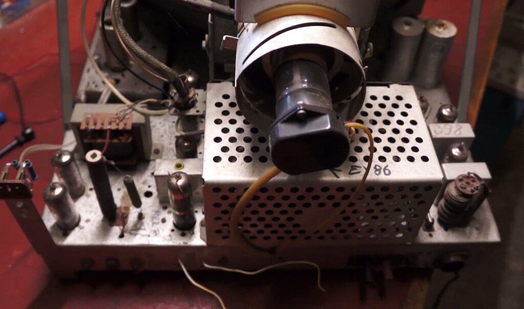
The CRT had been replaced, probably in the late 1960's, with a Sure-Brite, a local CRT building company. Originally, the set used a MW43-64 which is a magnetic focus type and uses an ion trap. Not surprisingly, the replacement was an electrostatic focus type with a straight gun. As such, it also has a shorter neck. In order to use this CRT, the existing focus magnets were removed. There is no type number on the replacement, which has me curious, because for a series heater circuit with European valves, the heater current must be 300mA. The most common 17" 70 degree replacement CRT was the 17CGP4, which has a 600mA heater.
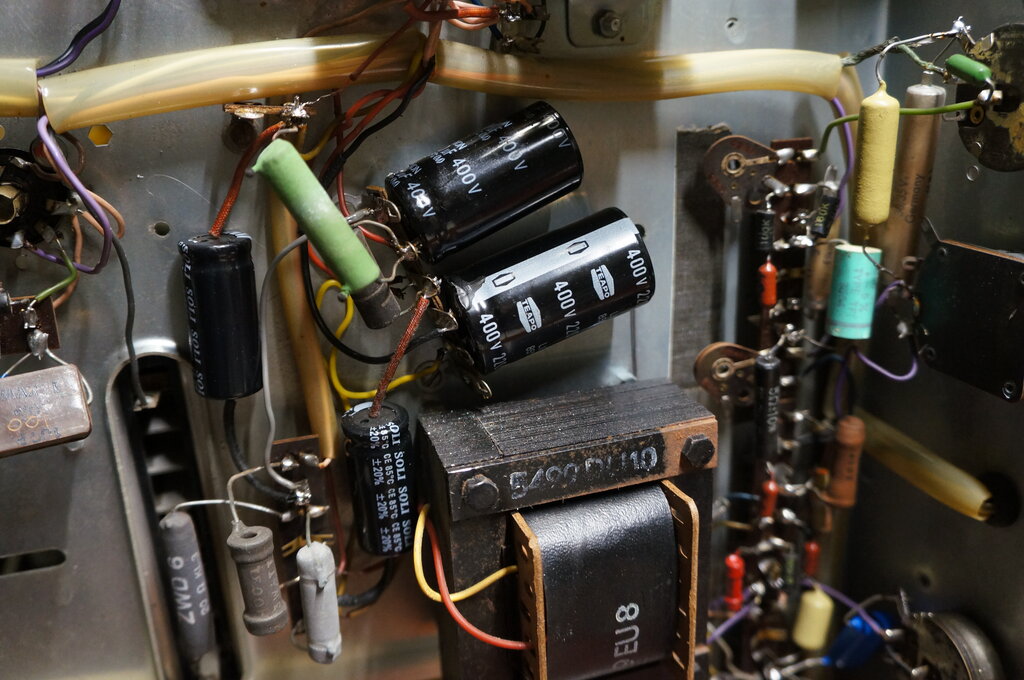
I had been told the set had been recapped and was working, although it wasn't working now. Indeed, looking underneath, someone had saved me a lot of work. It looked as though most of the paper condensers had been replaced in the late 1960's, but more recently so had a lot of the electros. And here the workmanship was quite interesting.
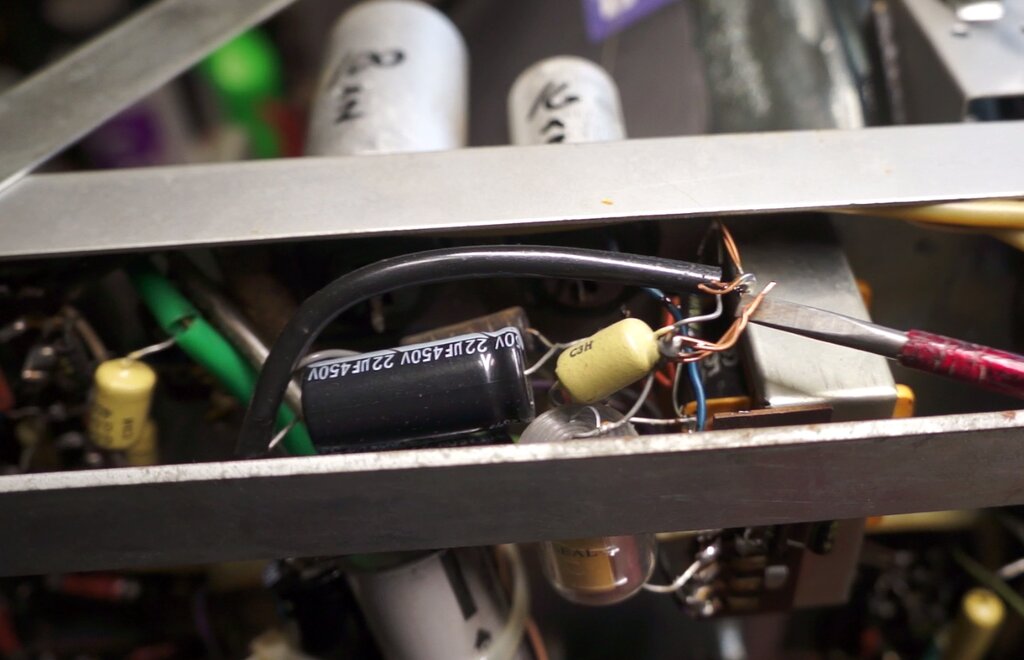
Earth wires terminating capacitors in mid air.
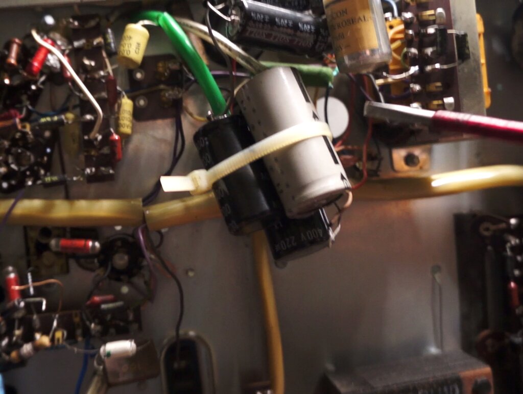
This bundle was hanging by various wires.
Note the unterminated original left in situ and the mid air join
for the replacement.
Note the two white wires hanging out the back. Obviously not original.
Tuner & Video IF.
The tuner is a conventional 12 channel
turret design with a variable capacitor for fine tuning. The RF amp uses
a PCC84/7AN7 in a cascode circuit. This feeds a PCF82/9U8 frequency converter,
with the triode as the local oscillator, and the pentode as the mixer.
From here the IF proceeds to a three stage
amplifier using EF80/6BX6 valves. Video detection is by a germanium diode.
Because of the live chassis origin, the aerial is isolated with 100pF capacitors.
Their reactance is minimal at VHF, but very high at 50c/s. Thus, the aerial
is not a shock hazard should the chassis be at mains voltage. Keep in mind
that the German Shuko mains plug is non polarised, so there is a 50-50
chance the chassis will be live. I would have liked to see static discharge
resistors across these capacitors, since static charges building up on
the aerial can exceed their voltage rating. It's doubtful that the tiny
current involved would do any damage, but could cause interference as the
capacitors flash over.
Video & CRT.
Being for negative modulation, the video
detector is direct coupled into the video amplifier; the pentode section
of a PCL81. This is the first time I have encountered this valve. It is
a triode pentode which seems to have been designed for audio amplifier
and output use. There is no RMA type number.
Contrast control is by a 1k cathode rheostat
which allows a degree of negative feedback. The pentode is biassed entirely
by the negative voltage produced by the detector diode, and the voltage
drop across the contrast control. The screen grid is held at a constant
voltage by a resistive divider. Plate load is a 5k resistor (R302) which
feeds the CRT cathode via a 5.5Mc/s sound trap (C302 & S302), and an
RC network (C310 and R303). This provides partial DC coupling between the
video amplifier and CRT.
Brightness control is by varying the grid
voltage of the CRT. In conjunction with this is the spot swallower circuit
using a third pole of the mains switch. When the set is switched off, this
third pole makes contact, feeding the full B+ into the grid. This sudden
increase in beam current causes the CRT to rapidly discharge the EHT, before
main B+ filter capacitors have discharged. Thus, a stationary spot is avoided,
which may eventually burn through the screen phosphor.
The CRT is an MW43-64. This is a 43cm (17"), 70 degree type with magnetic focus and a bent gun. European designs seemed to retain magnetic focus longer than in the U.S., but it was around this time anyway that magnetic focus was going out of fashion. By the time TV came to Australia, it was only sets using European or English CRT's that used it. The bent gun design was standard and was used to prevent ion burn. By setting the gun at an angle, the heavier ions simply hit the side of the CRT neck and do no harm. But, in order to bring the electron stream back to pointing straight at the screen centre, a small magnet is required. It is known as an 'ion trap'. Incorrect setting of this magnet can damage the gun, as well as cause a dim and/or defocussed picture.
Since the replacement is a later type with an aluminised screen, the bent gun and ion trap is not used. It is also electrostatically focussed. As a result, the focus magnets behind the deflection coils were removed, as was the ion trap magnet. The neck is shorter than the original. To work with the heater circuit, a 300mA heater is required. A 600mA heater can only be used if a separate 6.3V transformer is installed. If this is done, the heater string continuity must be maintained by substituting a 21R 5W resistor to drop 6.3V.
Sync Separator.
A triode pentode, type ECL80/6AB8 is used
to clip the video and amplify the resultant sync pulses. A sample of the
video is fed into the grid of the pentode. Because the screen grid is held
at a very low voltage (only 5V), and there is no initial grid bias, the
waveform appearing at the plate is very distorted. Effectively, the luminance
portion of the video signal is cut off, leaving just the sync pulses. The
triode provides further clipping and amplification. It too, operates with
no initial bias, which further removes any remaining luminance signal.
From the triode plate, the sync pulses feed the frame and line oscillators,
through simple low and high pass filters. This ensures that the frame oscillator
receives only the 50c/s pulses, and the line oscillator receives only the
15,625c/s pulses.
Frame Oscillator & Output.
Another ECL80 is used here; the triode
for a blocking oscillator, and the pentode as the output. As is typical,
the oscillator is fed from the 460V B+ Boost supply. R408 (1.6M) charges
C405 (.1uF) to form the rising part of the sawtooth waveform. By using
the higher voltage, it means the associated resistor can also be made high
and the charging current is more constant. This gives a more linear waveshape.
The capacitor discharges when the triode conducts - caused by the blocking
transformer causing positive feedback. The frequency at which this occurs
is determined by the grid components. The sync pulses are integrated by
an RC filter R404, R403, and C401-403, prior to being used to trigger the
oscillator.
The output stage uses the pentode. The
sawtooth wave is fed into the grid via the height control which works like
an audio volume control. Linearity is adjusted by adjusting a negative
feedback circuit, whereby a portion of the plate voltage is fed back into
the grid.
A peculiarity of this circuit is a control
labelled, "frame width" - a paradox of terms! This is an adjustable resistor
in series with the charging capacitor, C405. I am uncertain why this is
adjustable. In fact, adjusting it did very little except reduce the height
slightly at one end of its travel.
The frame deflection coils are fed from
the output transformer in the usual way. There are 2k damping resistors
across each of the coils.
An unusual aspect of this circuit is that
the CRT blanking circuit is fed from the oscillator, and not the output.
It can be seen the earthy end of the brightness control is fed from the
junction of the charging capacitor and the previously mentioned frame width
control. As the triode conducts, the capacitor discharge current creates
a negative pulse of about 90V, which pulls the CRT grid negative by a similar
amount, cutting off the beam during retrace.
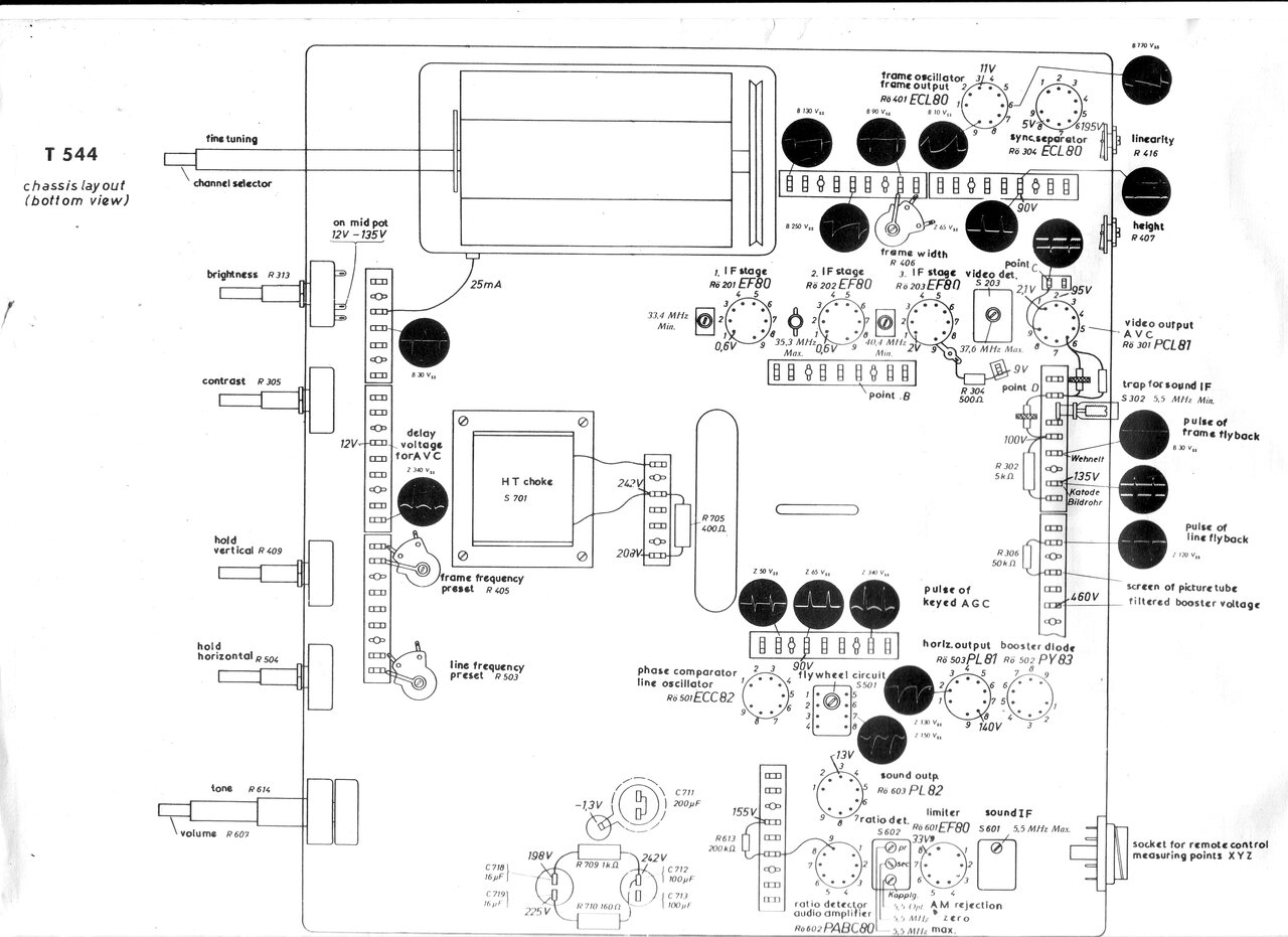
Diagram shows test points and adjustments.
Line Oscillator & Output.
As is typical with most negative modulation
sets, the line oscillator is not directly triggered by the sync pulses.
This is because noise pulses are of the same polarity, and could give rise
to jagged edges to the picture. Instead, a phase locked loop is used, more
commonly known as AFC (Automatic Frequency Control).
A close look at the circuit around the
ECC82/12AU7 shows it's actually based on RCA's Synchroguide circuit. In
this circuit, one triode performs as a phase comparator and the other is
a blocking oscillator. In more detail, the triode using pins 1,2,&3
is the phase comparator.
Into its grid is fed sync pulses, via
C501 (50pF), and pulses from the line output stage via C502 (100pF). The
cathode current is greatest when the sync pulses and feedback pulses are
in phase. This cathode current is filtered to produce DC, by C506, which
then controls the oscillation frequency. Here, a long time constant is
introduced so the sync pulses are averaged over a period, making the circuit
largely immune to individual noise pulses. If the sync pulses are obliterated
completely, the charge on C507 (5uF) will maintain the control voltage
for a short period.
If the sync pulses are not in phase, an
error voltage is produced to bring the line oscillator back on frequency
and phase.
The oscillator is of the blocking type,
with a tapped coil in the plate circuit. Frequency is determined by this
coil in conjunction with C508 (500pF), and the resistance of the grid circuit.
Additionally, some control of frequency is dependent on the grid voltage
- which is dependent on the output from the phase comparator as described
previously.
There is also a tuned circuit consisting
of C509 (.005uF) and S501. This is set to 15,625c/s and improves stability
of the circuit.
The sawtooth from the oscillator feeds
the line output valve, a PL81/21A6, via C511 (.0025uF). The line output
circuit is conventional, although there's a few interesting points. There
is a 16k resistor in series with the EHT winding. The function is not clear,
but could be to dampen any ringing (and possibly improve regulation). I've
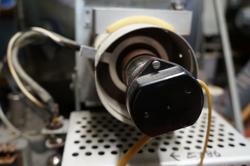
not seen this in any other set before. The EHT rectifier is an EY86/6S2.
Apart from the Ekco sets, which also use this valve, most other sets use
the DY86/1S2. The DY86 has the advantage of less turns for the heater winding.
The line output transformer is the auto
type, with the deflection coils fed from a tapping on the primary winding.
Tuning is performed by C518 (300pF) in series with C517(also 300pF). Width
control is by a variable inductive shunt.
The damper diode is a PY83, and the circuit
is conventional. This valve does not have an RMA type number. The boost
capacitor is C505 (.05uF), and charges during the retrace to a voltage
somewhat higher than the B+ (460V). It is well to remember that the line
output valve plate is supplied from this voltage, and not the normal B+.
AGC.
This is of the gated type, so that AGC
is dependent only on the sync pulse strength and not the luminance signal.
This means the AGC gives a true indication of signal strength, and is not
influenced by the picture content.
The negative AGC voltage is produced by
the triode of the PCL81 which acts as a variable rectifier. This rectifies
pulses from the line output transformer, via C504 (500pF). The plate voltage
from the triode is filtered to DC by R217 (50k) and C208 (2uF), and fed
to the grids of the first and second video IF amplifiers, and also the
RF amplifier. The higher the negative voltage, the lesser the gain.
As to what controls the variable rectifier,
this is the video signal itself. Note that the triode shares the same cathode
as the pentode video amplifier, and there is a resistor of 500R to earth
(R304). Therefore, video signal is introduced into the triode, which is
now operating in grounded grid configuration.
The important point is that the line output
circuit is the source of the triode's plate voltage. Since the line output
is locked to the sync pulses, it follows that the triode can only conduct
when the sync pulses are transmitted, and not during the luminance part
of the signal. Now, since the video strength determines the conduction
of the triode, it then follows that the rectified voltage is produced only
during the sync period, and is dependent only on sync pulse strength. The
reason sync pulses are used is because they remain constant in amplitude
(peak transmitter power), regardless of the scene content.
The RF amplifier has a delay circuit,
with a small forward voltage fed from R202 (10M). This ensures the RF amplifier
gain is not reduced on weak signals, since there will always be some negative
voltage produced by the AGC circuit. For best signal to noise ratio, the
RF amplifier should work at full gain on weak signals, and be reduced before
the signal is strong enough to risk overloading then following stages.
Another delay circuit is formed by R214
(1M) which is fed from a negative 1.3V source. This prevents the triode
of the PCL81 conducting unless there is a definite video signal, so as
to prevent the gain of the front end being reduced unnecessarily by noise
and weak signals.
Sound IF Amplifier & Output.
The 5.5Mc/s sound IF is taken from the
plate of the video amplifier since the latter adds some extra gain for
nothing. It is coupled in the EF80 sound IF amplifier by C301 (4pF). Since
the EF80 is operating with grid leak bias only, it also functions as a
limiter, removing any AM content in the FM signal. By operating with low
bias and a low screen voltage, the plate voltage is restricted, and any
signal above a certain level is clipped off. A ratio detector is used to
detect the FM. This uses two diodes of a PABC80/9AK8. Also in this valve
is a triode, used to amplify the detected audio. This feeds a PL82/16A5
audio output pentode; a largely conventional design, except for the feedback
circuit. They've gone to the trouble of providing an extra winding on the
output transformer for feedback only. One probable reason for not using
feedback from the voice coil circuit is that it's a live chassis set, and
to do so would mean the speaker couldn't be isolated.
The feedback circuit incorporates the
tone control, which is in the plate circuit of the PABC80. The other end
of the feedback circuit feeds the earthy end of the volume control in some
kind of loudness or frequency compensation circuit. Obviously, SABA thought
the sound quality was more important than most Australian manufacturers
- some of which provided no feedback at all.
The speaker is isolated, although bypassed
for RF to earth via C621 (.005uF). External speaker terminals have been
provided.
Remote Control.
In the modern day the remote control of
this set would be seen as a joke. It can only control brightness and volume.
The important function of channel changing is omitted. However, this kind
of control was typical of the time. To change channels required a motor
to drive the tuner, and a set of contacts to stop the motor on the preset
channels. Such remote controls were available and were used, but added
to the cost.
There is a 9 pin valve socket at the rear
of the chassis into which the remote control connects. In view of the control
being at mains potential, the insulation of the connecting cable would
have to be suitably rated. The remote control socket is also used to connect
a meter for the purpose of sound IF and ratio detector alignment. There
is a mistake on the circuit; C610 which is connected to pin 3 of the socket
is 5uF and not 5nF (.005uF).
Power Supply.
Being of German origin, the set was designed
for 220V operation. There is a mains input filter (S702) which is two Litz
wire RF chokes and two .005uF capacitors to earth. Since all the valves
are of the standard "P" type, the heaters are 300mA. The valve heaters
are connected in series in the usual way, and then in series with a 240R
35W dropper resistor. In the version made for Electrosound, an additional
70R resistor is included, to bring the dropper resistance up to 310R for
240V operation. Note that this extra resistor is not shown on the circuit
diagram. Various chokes and capacitors along the heater string prevent
undesirable coupling between stages.
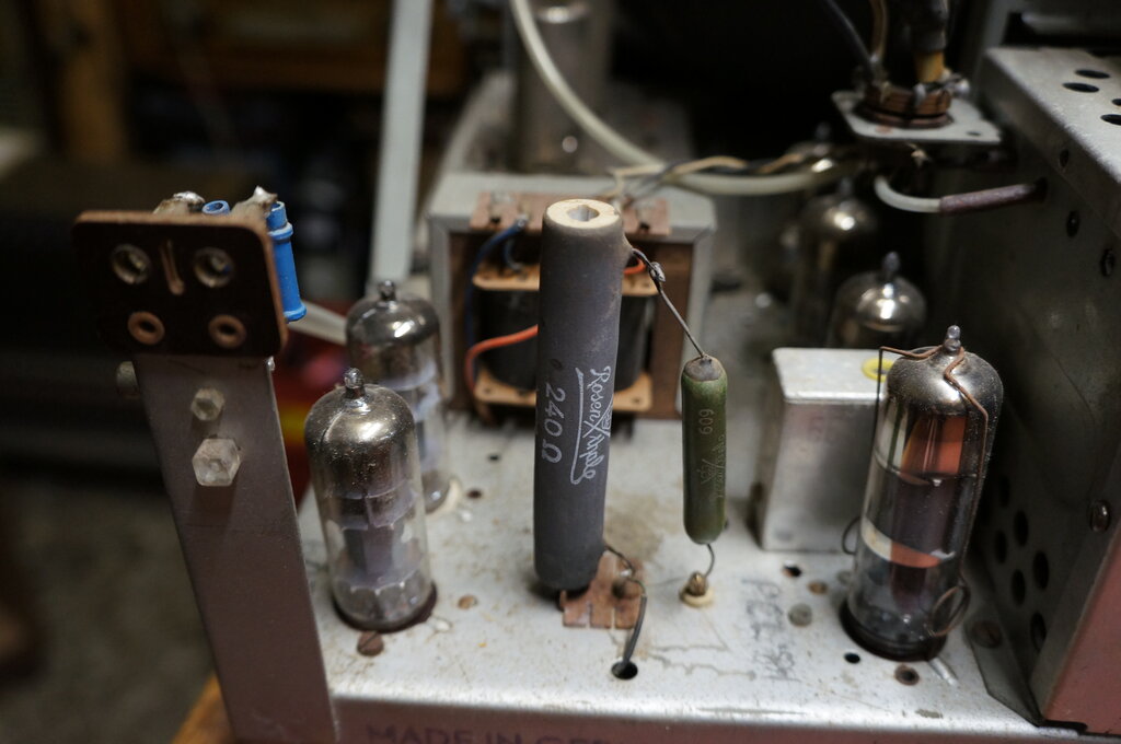
Heater droppers. Original 240R on left, added 70R on right.
The B+ comes from a selenium rectifier.
Again, not shown is the extra resistor for 240V operation. In series with
the 10R anti surge resistor (R703) is another 20R resistor, so the B+ remains
correct on 240V mains. A conventional pi filter with a choke and electrolytic
capacitors provides a B+ of 242V. Further resistive filtering and capacitors
also provides rails of 198V, 225V and 208V.
Note that there is a 5R back bias resistor
(R704) to provide the -1.3V AGC delay. For this reason, the heater circuit
is not returned directly to the chassis, and neither is the first filter
capacitor.
In theory, the set could be used as is
on the local 240V mains, since the aerial and speaker are isolated, and
the knobs are plastic. However, Australians have an aversion to live chassis
sets (it's an odd thing since the rest of the world gets along with them),
and in fact the other popular manufacturer of live chassis series heater
sets, Ekco, was forced to switch to transformer power supplies because
of the opposition. To avoid being unpopular, Electrosound provided a 240V:240V
isolation transformer mounted in the bottom of the cabinet. This is fed
with the mains supply while ever the set is plugged in and turned on at
the power point, since the set's on/off switch operates after the transformer.
The transformer is a 130VA type made by Henderson. It is fitted with a
conventional two parallel pin socket of U.S. pattern, into which the TV
chassis connects.
It is a point of speculation that the
transformer provided could have been 240V:220V, obviating the need for
the extra two dropper resistors. However, 240V:240V transformers were already
a standard line, and to specify a 220V secondary would no doubt increase
the cost.
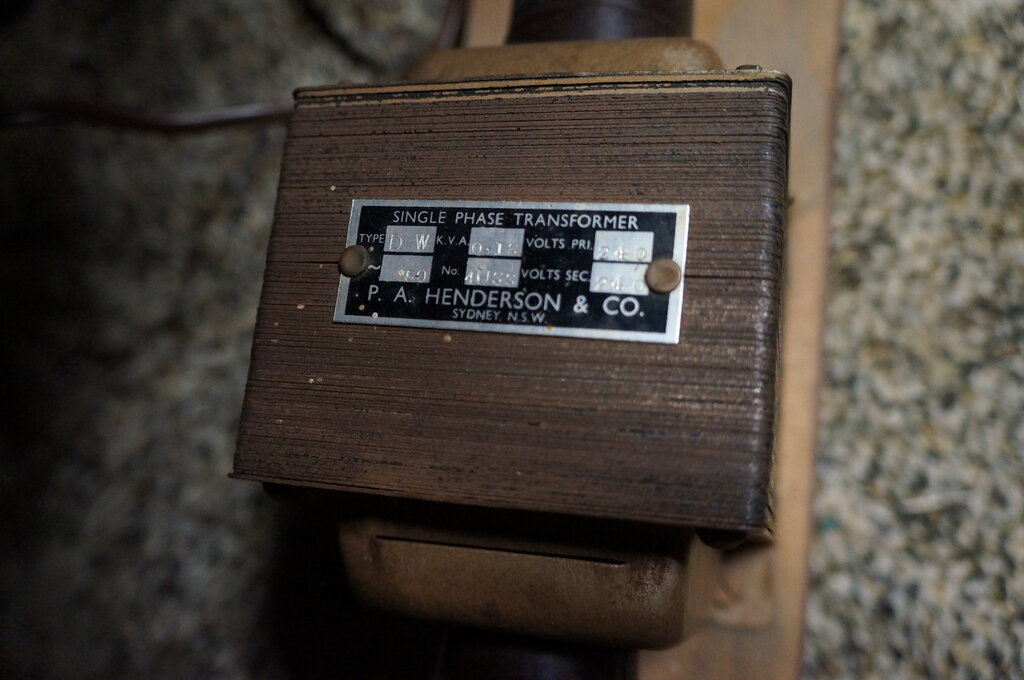
Isolation transformer is 240V:240V at 130VA.
New tagstrip for capacitors.
A trap is the tag mounted under the 200uF filter (C711). This is not an earth tag. Our would be restorer had used it for this purpose, terminating some of the other replacement capacitors to it, and I almost fell into the trap also. The tag connects to the body of this capacitor, which is insulated from earth, and thence to earth through the 5R resistor (R704). Shorting this tag to earth shorts out the AGC delay voltage.
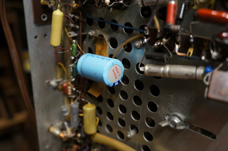
Don't shock! This is the 4uF boost filter replacement (C513). One
wonders where this came from.
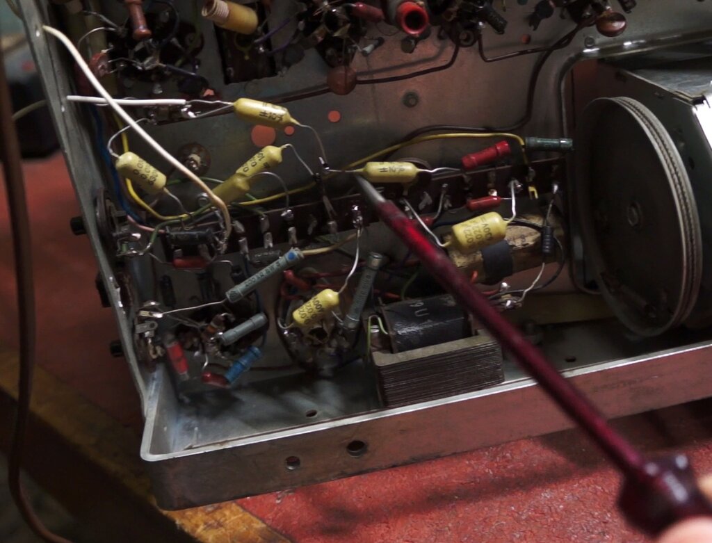
As I worked around the chassis, I found several instances of high voltage capacitors being used where a low voltage type was applicable. This is wasteful of less common high voltage types, and they are also larger than necessary. One example was the PL82 cathode bypass; normally a 25V type would be used, but here our would be restorer had used a 350V type. As it turned out, the original was still hanging by one lead and tested perfectly OK, so I reused it.
47uF 350V electrolytic where 47uF 25V would have done. Note the
mid air earth connection. Original is to the right hanging by one lead,
and was reused.
Another strange thing was a capacitor wrapped in foil with a wire twisted around it. This turned out to be C611, the audio coupler to the PABC80 grid. Obviously, the original was a shielded capacitor which is used to reduce hum pickup.
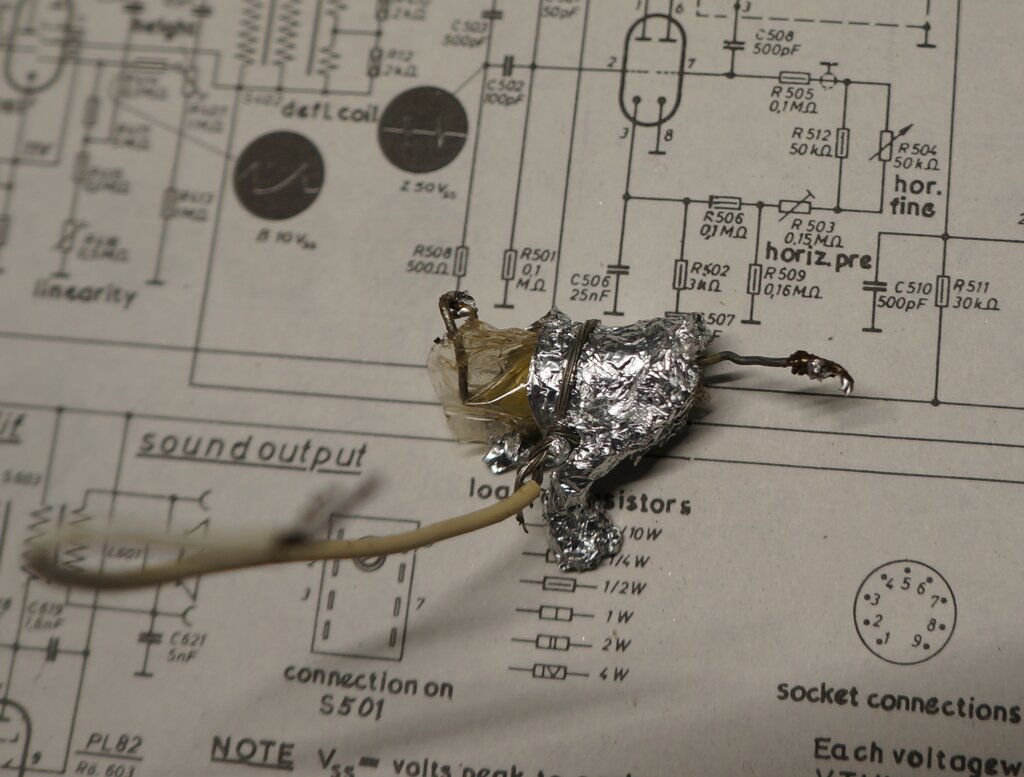
Crude method of shielding an audio coupling capacitor.
I cut a piece of copper and soldered it together to remake the shield. Another bizarre modification were two wires hanging out of the back of the chassis, poked through convenient holes, labelled in pencil; "hot" and "earth". One was connected to earth, and the other was via another mid air connection to a .01uF capacitor, which then went to the the junction of C403 and R403. This is the sync input to the frame oscillator. I cannot imagine any need for this. To extract frame sync? To feed in frame sync?
Why? External wire connected to sync input to frame oscillator.
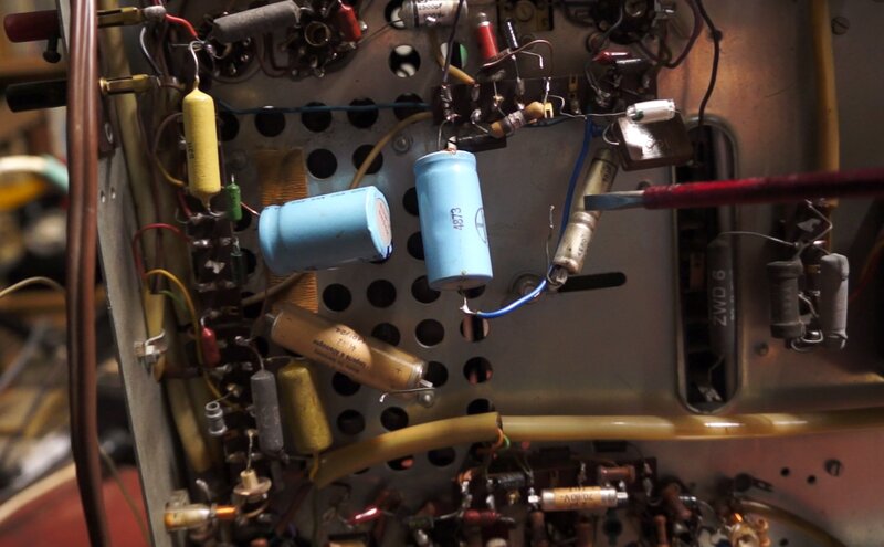
There were still a few paper capacitors left. Importantly, was an interesting dual .1uF in the vertical circuit. It is surprising our previous restorer didn't replace it because it tested quite leaky, and would have prevented proper height and linearity being obtained. Although the .1uF across the mains (C701) tested very good, I felt it best to replace it in case it shorted from the continuous application of 240V AC.
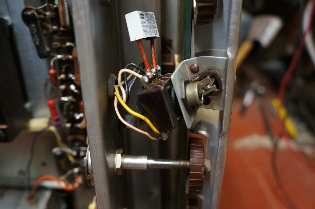
Mains switch. Key can be removed to prevent unauthorised viewing.
Note replacement filter capacitor.
Someone had written the valve type numbers on the chassis in pencil. One drew my attention - a 6EH7 in the position of the sound IF amplifier. There is no way this was original, since the 6EH7 is a frame grid valve introduced several years later. It is pin compatible with EF80/6BX6, which is presumably why it was used. Since this valve has twice the gain of a 6BX6, I felt it inappropriate and put back the correct EF80. Because of the higher gain, there is the risk of instability, and/or regeneration - which could reduce the bandwidth, and thus introduce distortion of the FM signal. High gain valves shouldn't be used as a plug in replacement just because they have the same pin connections. The circuit must be designed for them!
Power Up.
Nothing happened except the heaters lit
up - that is except for the EY86. Obviously the line output wasn't working.
Eventually, I learned that touching the grid pin of the PL81 with a screwdriver
would get it going. And, it came up with a pretty good picture. The CRT
was in excellent condition.
I had noticed that a 17Z3 was in the damper
socket. This is equivalent to PY81, not PY83. While it is an acceptable
valve since the ratings are adequate, the heater is 17V instead of the
PY83's 20V. It is true that an extra 3V spread over the entire heater string
is not really important, but because I had some PY83's, I did the correct
thing and replaced it. Later, I found that a couple of other Electrosound-SABA
models actually specify either type on their circuits.
Tidied up chassis.
Channels.
Quite a few European sets have found their
way into Australia, since the systems are the same, and the mains voltage
close enough. Some sets were actually imported and sold here, while others
were brought in by immigrants or duty free purchasers. One difference is
the channels - most of them are the same as the Australian ones, but the
channel numbers are not the same. For example, Australian channel
2 is received on channel 4 on a European set. European channels are compatible
with those used in Australian capital cities, so most sets were used with
the owner being none the wiser. However, European sets do not cover the
post 1961 Australian channels 3,4,5, and 5A.
This could be problematic in some rural
areas where these channels were used.
I was curious if the SABA was fitted with
European or Australian channels. As it turned out, all channels were correct
for the original Australian 10 channel plan, which was in use from 1956-1961.
The local oscillator needed a touch up on all channels. I retuned channel
1 to the later channel 0, since some modulators work on this channel.
Resistors.
On the first power up, the width started
to decrease after about half an hour. Normally, this fault is caused by
the boost capacitor, but this had been replaced. Drive to the PL81 could
be a problem, and this is when I found the 500k grid resistor completely
open circuit. Replacing it fixed that fault, and the width remained perfect
from then on. Another thing I noticed was the brightness control was very
restricted, in that the brightness could not be turned down very much.
This turned out to be R307 (500k) being open circuit. It's in the CRT cathode
bias circuit.
PL81.
Every time the set was switched on, the
PL81 needed to be disturbed by touching the grid pin with a screwdriver
to get the horizontal output working. Looking at the grid waveform, it
could be seen that as the set warmed up, the line oscillator started normally,
but then suddenly stopped. I recalled somewhere about a line output valve
needing to be touched on the grid pin, which was due to a valve fault.
Replacing the PL81 fixed that. Later investigation showed a heat sensitive
short circuit between the control and screen grid.
Centering.
It was noticed, particularly with the
test pattern that the picture centering was in need of adjustment. Unfortunately,
what remained of the centering magnets did virtually nothing. What remains
of a 'magnet' appears to be all aluminium, so I'm not sure how it could
do anything. Normally, there are two magnets mounted around the neck of
the CRT, and the further apart the magnets are rotated relative to each
other, the stronger the magnetic field. Turning the whole assembly then
adjusts the direction in which the beam is directed.
Here, we just had one 'magnet' which wasn't
anything of the type. My guess is that the centering magnets were part
of the focus magnet and were removed when the CRT was replaced.
What remains of the centering magnets.
What to do? Experiments showed that a small bar magnet could be used to pull the picture into the correct position. So, with some double sided tape and a cable tie, a magnet was mounted on the deflection yoke cover. The centering is not perfect but it's much better than it was. In fact, it's really only noticeable with the test pattern and not off air pictures.
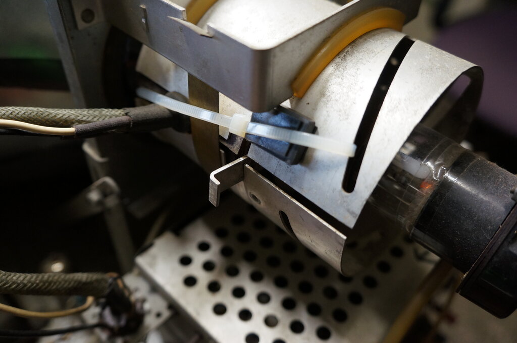
Missing centering magnets required this bar magnet to be mounted
on the yoke cover.
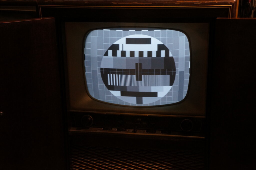
Centering much improved. A stronger magnet might pull the picture
up a little further.
Sound Detector.
Frame buzz was evident on peak whites.
A set of this quality should not suffer this problem, and so the ratio
detector coil was adjusted, first for maximum output and then for correct
balance. Sound was now stronger and largely free of buzz.
Power Consumption.
The standby current was measured. This
is the magnetising current of the isolating transformer.
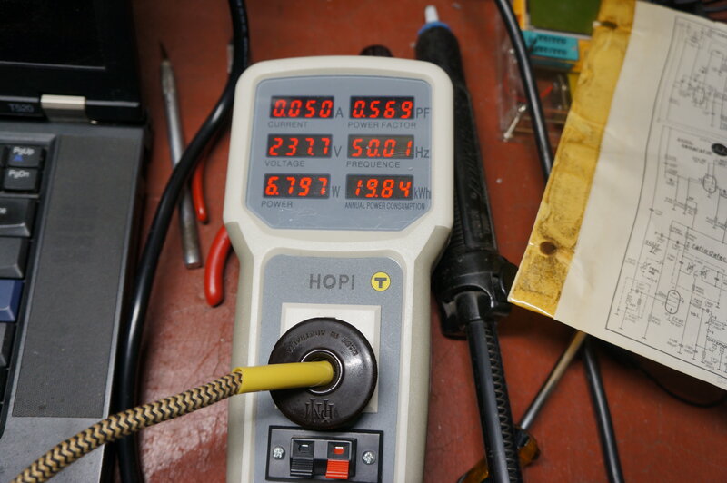
6.8W drawn by the transformer with set switched off.
Since the transformer is always connected to the mains, and not switched by the set, some current is always drawn. In this case, the owner has to pay for an extra 6.8W being drawn whether or not the set is switched on. In reality it's not that bad. Going on 19.84kWh per annum, at current rates; about 27 cents per kw/h, annual cost is only $5.36.
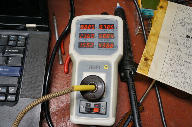
150W with the set operating. One wonders how the 130VA rating was
determined for the isolating transformer.
As can be seen, the 130VA rating of the transformer is being exceeded. It should be at least 190VA, (.8A x 237V), and higher than that again because of the DC component, due to the half wave rectifier. The transformer does run warm, but it's obviously lasted all these years.
CRT Neck Cover.
Missing from the back was the cover which
goes over the neck of the CRT. It would be all too easy to break the neck
or the base off it, if the cabinet was pushed too far against a wall, or
otherwise got knocked by something. At first I thought of bending up an
aluminium box like cover, but I had a plastic moulding which would be more
appropriate.
CRT neck cover missing. Hole is 5".
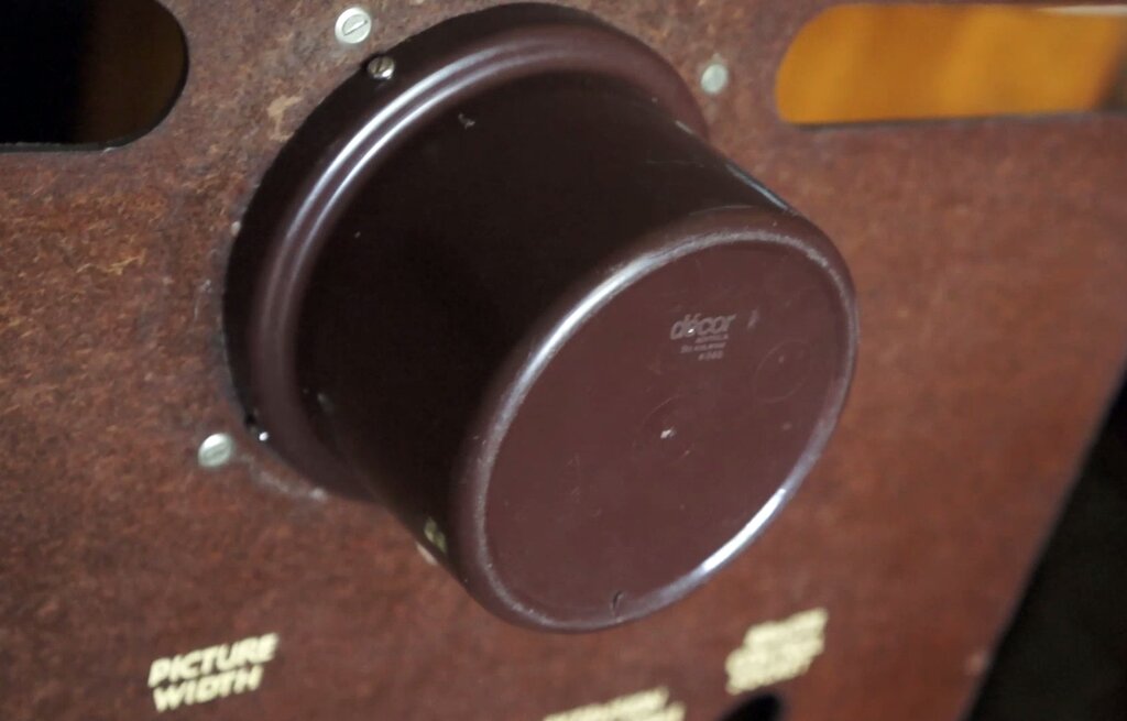
New cover looks original.
The moulding appears to be a small pot
plant holder or possibly some kind of kitchen accessory. It's from the
Australian company, Decor, who made such things. It was a perfect press
fit into the hole in the back, but I made up some brackets to secure it
properly.
Funnily enough, this moulding came to
me in a whole lot of TV parts, so maybe someone else had the same idea.
Conclusion.
There must be an irony, in that like the
live chassis series heater Ekco
sets, the SABA was a pleasure to work on. Everything is clearly laid out
and accessible. Of particular note is that component leads are simply soldered
to the tags, without being wrapped around them multiple times. Component
replacement is so simple. Compare this to sets like AWA and Kriesler, which
are a pain to work on, with most of the time unpicking leads from tagstrips
and valve sockets.
The CRT being mounted on the chassis further
improves serviceability, since the whole thing can be put on the bench
and powered up, without the inconvenience of extension leads or a test
CRT. Unlike Australian made sets full of IRC resistors, I found only two
resistors in this set had to be replaced.
Performance is very good. The IF and video
bandwidth easily passes the 4.43Mc/s chroma signal. Not surprisingly, the
sound quality is also very good - and the tone control does what it should.
My only reservation with the Electrosound-SABA
is that the isolating transformer is always powered. On a positive note,
the small amount of warmth it radiates is probably a good thing in keeping
moisture out of the set.
In short, a highly desirable set from the early days of TV in Australia.