This set was obtained from a deceased estate
in Sydney. The owner bought it in 1957 and was actually employed by the
company that made it.
The Ekco brand is well known in the U.K.,
but its time in Australia was short. It appeared here with the introduction
of television in 1956. Products were assembled by A.E.I. (Australian Electrical
Industries) at Yennora, under licence to Ecko in the U.K. While in
Australia they were mostly known for television, there was also a popular
Ekco mantel radio known as the "Gondola". I have also seen light
bulbs stamped with the Ekco brand. For those wondering where the name comes
from, it's an abbreviation of E.K. Cole.
There were three series of Ekco TV sets.
The most well known are the 17" and 21" 70 and 90 degree sets from 1957-1958.
There is also a 9" portable, the TX-275 which can operate from 12V as well
as 240V. The last generation of sets were the 21" and 23" 110 degree sets,
which were produced up until about 1961. From then on, Ekco ceased to exist
in Australia.
The main design feature that set Ekco apart
from the other Australian manufacturers, was the live chassis, series heater
power supply. This was standard in the U.K and Europe, but not in Australia.
Because of the possible shock hazard from this kind of design, it was never
popular in Australia amongst manufacturers or technicians. Radios had been
produced in a small quantity for DC mains districts using this technique,
but it was somewhat begrudgingly. Australians were used to a chassis that
could be safely touched and earthed, regardless of mains polarity.
When Ekco appeared on the scene with their
transformerless power supply, they thought it would be a good marketing
tool. Cheaper, lighter, and according to the advertisements, "uses one
third less power". Obviously they didn't realise that Australian servicemen
hated the design. It is quite possible that the notoriety caused Ekco to
use a conventional transformer power supply with their last generation
of Australian sets.
The unfortunate outcome of this is that
despite their popularity at the time, few Ekco sets survive in the present
day. One can imagine service technicians advising that the set was "not
worth repairing" at the first opportunity.
As can be seen from my article on the
Ekco
TX-287, my attitude is quite different. Common sense would make one
think that all one needs to do is plug the set into an isolating transformer
when servicing. It appears the Ekco hating servicemen overlooked the obvious.
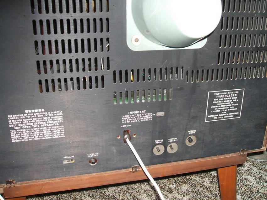
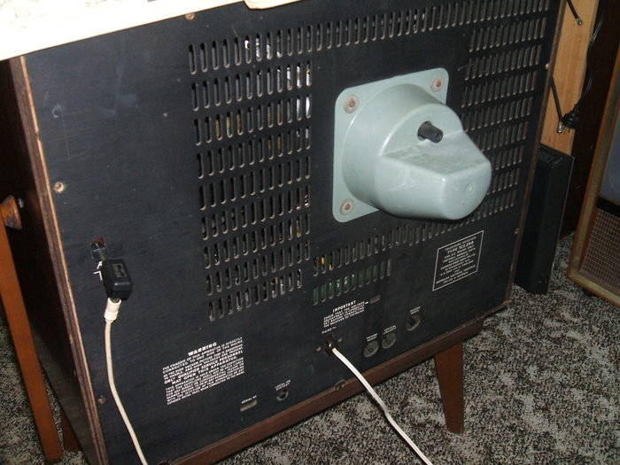
Note the warning about the chassis being live. The mains connector
is not original, but fits. The original was screwed to the cabinet back
to prevent operation with the back removed. Unfortunately, originals in
good condition are rare now as the rubber insulation deteriorates.
The design of the sets as a whole really
appeals to me. The serviceability is excellent, and there's nothing weird
about the design to cause problems.
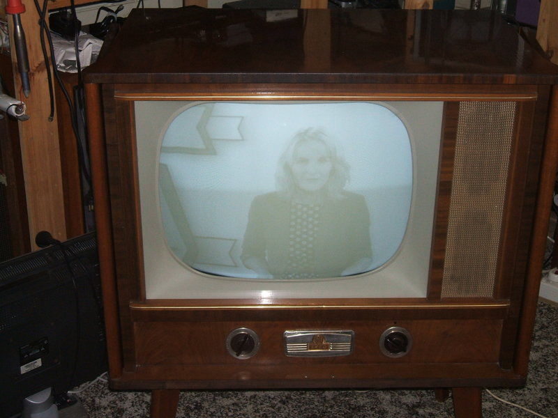
So, when one of my HRSA aquaintances found
this set, I had to have it. Especially as it had a cabinet with doors.
A deal was made and it was mine.
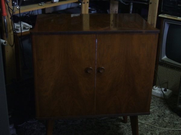
I've always liked doored televisions, and to have a series heater
live chassis model is perfect!
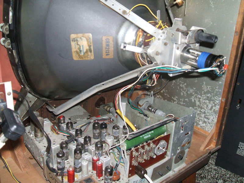
Despite the lack of a power transformer, this set is surprisingly heavy. I think that is largely because of the thick plywood cabinet. A quick internal look showed a new Thomas CRT had been installed in 1972. Interestingly, it was still a magnetic focus type. Often a conventional electrostatic focus CRT would be used as a replacement, in a set originally using magnetic focus, and the focussing magnets would be removed. One possible reason is that the CRM212 has a 12.6V 300mA heater, so one has to also install a 6.3V transformer if one used, say, a 21CBP4 as a replacement. In otherwords, it's easier in this set to use the original type as a replacement. It's fortunate too, because the focus is far superior to that of electrostatic tubes.
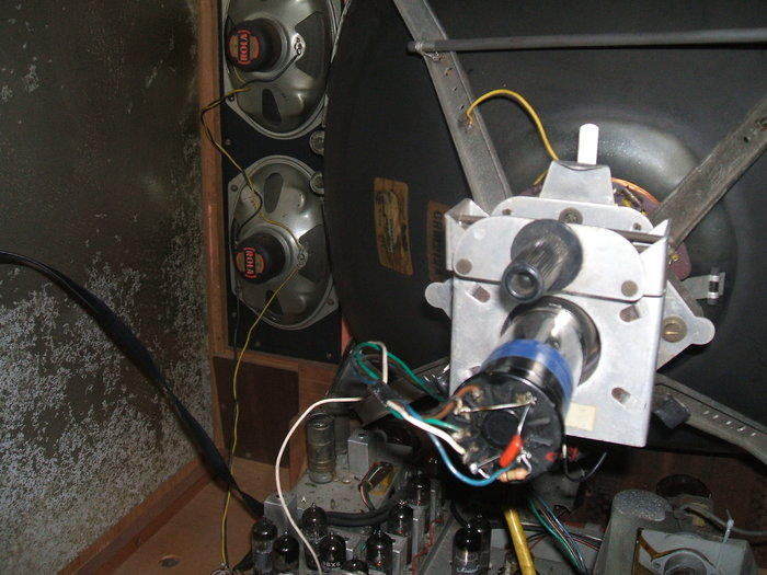
The replacement CRT has no ion trap, but is still magnetic focus.
Note the Metrosil VDR across the top. It is for EHT voltage regulation.
The line output transformer had been replaced.
This was to be expected, as the original Ekco type was made of a plastic
that crystalised in the presence of EHT. It would thus crumble apart leaving
the transformer core supported only by the connecting wires. Telecomponents
made a replacement type of far superior quality with the transformer supported
on paxolin panels. One change with the replacement is the EHT rectifier
is now a 1S2 instead of the original 6S2.
A further observation was that the Metrosil
EHT regulator and EHT filter condenser had been disconnected. The Metrosil
is a long VDR mounted across the top of the CRT. Evidently there had been
a fault in either of these causing loss of EHT. With the modern CRT, the
EHT condenser is not required, and it is questionable as to how essential
the Metrosil is. In view of the focus being very dependent on EHT with
a magnetically focussed tube, this would probably explain the Metrosil,
but in practice it works very well without it.
The aerial connection had me interested. Most Australian sets used screw or spring terminals, but a few used a two pin socket of similar pattern to a 300 ohm ribbon connector. For my TX-287 I'd been using a plug, which while not correct, fitted well enough. For the TCX-298, the plug was still in the socket with an inch of wire still attached; this being transparent figure eight mains cable, popular in the 1950's. The plug was made by Belling Lee, and it was clearly evident looking at the cable entry, that it was designed for 'lamp cord' rather than 300 ohm ribbon. This shouldn't be too surprising perhaps, as lamp cord had been used as transmission line with some early British sets. It's perfectly viable for this, but the impedance is closer to 150 ohms. The line from the socket to the tuner is normal 300 ohm ribbon. I'm not sure if the impedance mismatch was meant to be of concern, especially if the lamp cord transmission line is only a few feet to the wall socket.
The mains voltage selector was on 230V
instead of 240V. I hope this wasn't done to mask a fault, because such
tacticts over run the valve heaters. Strangely enough, my TX-287 was the
same when I first got it. No mains cable was present. It uses a two round
pin connector; one pin of larger diameter than the other to keep the polarity.
Like the TX-287, it appeared the original connector had deteriorated and
the mains wires soldered straight to the pins, as there was solder on the
ends. I didn't have any spare leads, as both were in use for the TT-207
and TX-287. However, I remembered I had some leads off some long forgotten
test instruments that had a similar connector. Much joy when I found they
fitted!
General condition inside was excellent;
in fact it was really like new. No grime or corrosion. Looking under the
chassis showed that some paper condensers had been replaced, and that the
selenium rectifier had been bypassed with silicon diodes. The volume/brightness
control had also been replaced.
Broken channel knob.
I'd noticed the channel knob felt a bit
spongy when rotated. At first I just put this down to the grub screws being
loose, but then it felt really spongy and it was obvious the shaft had
broken. Apparently, the tuner mounting on the chassis had moved out of
alignment causing the knob to bear heavily against the wooden front panel.
So, each time it was rotated, the shaft was under angular stress. The early
Ekco knobs are rare, so I had two options; replace it with a white one
I had of the same style, and paint it brown, or fix the original. As it
turned out, fixing the broken knob was not only very easy, but made it
far stronger than it was originally. To start with, I superglued the break
back together. This would be fine for a volume control, but given the torque
required to turn a turret tuner, it obviously wouldn't last long. It so
happened that 1/2" copper tubing was a good fit over the whole shaft. So,
I cut a piece, but with notches at the end which engaged in the hollow
parts of the paddle shaped part of the knob. Thus when the knob was turned,
all the force would be applied to the copper tube only, and thence to the
collar containg the grub screws. No force would go through the repaired
join.
With the tube suitably shaped, the
plastic shaft was covered in Quik Steel epoxy and the tube slipped over.
This epoxy is much stronger than ordinary Araldite kinds.
I suspect one reason few Ekco knobs have
survived is that the uninitiated are not familiar with how to get them
off. It is not possible to extract the chassis until the knobs are off!
Because of the live chassis, normal push
on knobs could be seen as a shock hazard - someone pulls one off, touches
the shaft, and gets a shock. So, the knobs are secured with grub screws,
and these are not accessable from outside. For the early paddle shaped
knobs, there is a ring around the knob, labelled as to the function. This
is secured with a wire clip around the knob. This needs to be removed,
along with the ring. Then the chassis will slip out with knobs still attached.
For the later models with fluted knobs, it's similar, but the outer fluted
part is pulled off.
Chassis restoration.
Like with any other 1950's television,
getting the set going again is largely a matter of replacing all the resistors
over 47K as these drift high, especially if they're made by IRC. Also,
all paper condensers must be replaced wherever leakage could cause problems.
For example, a paper condenser across a 150R cathode resistor will not
cause a problem if it's leaky, but when used as a grid coupler it certainly
will. And, in recent years, mica condensers have become a problem, so they
usually need replacing too. The only paper condenser left in the TCX-298
is the 2uF across the filter choke, and the .1uF across the mains. A small
amount of leakage here will cause no problems. The mains filter condenser
is a sealed type so I felt reasonably confident leaving it in. I would
have replaced it had it been a waxed dipped type. In any case, it's after
the mains fuses, so no catastrophe if it fails.
Replacing all the parts in the Ekco is
easier than most other sets, because instead of using tagstrips with the
wires wrapped around them, insulated pillars are used and the leads simply
slip off as the solder melts. I had the whole thing done in a couple of
days.
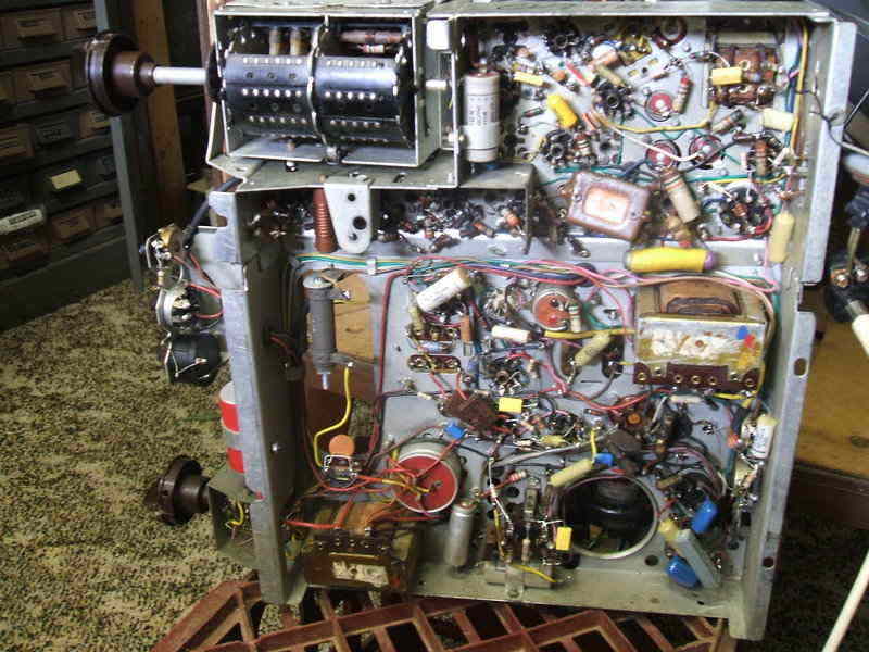
Under the chassis after restoration. Towards the front of the chassis
is the 20R 20W resistor occupying the space where the selenium rectifier
was.
Prior to applying the mains straight to the set, I decided to reform the electrolytic condensers across the B+ line. As the set had not been switched on for many years, and with the mains fed rectifier, there's not much to limit the current if they should be leaky. So, I simply unplugged the CRT so the valve heaters would not draw current, and connected a 40W light bulb in series with the set. After about 20 mins the bulb had dimmed sufficiently to indicate leakage current was now at a safe level.
I had noticed early on that the PCF80/9A8
converter valve was cracked, so this had to be replaced for the tuner to
function. I also fitted a set of channel 3 biscuits to the tuner.
As the sets were sold, they only had biscuits
for channels 1, 2,6,7,8,9, and 10 fitted. At that time, rural TV services
were off in the distant future so only potential capital city channels
were catered for. Some set manufacturers did not include all ten channels,
probably as a cost cutting measure.
As is well known, that was all to change
by the early 1960's with a revamped 13 channel plan, and the introduction
of services outside the capital cities.
It so happened that one of my later model
spare parts chassis did have all the biscuits fitted for the old 10 channel
plan, and used the same tuner. So hence the source of channel 3 biscuits.
Channel 3 is one of the output channels for many VCR's and with no off
air signals now, it was important to include it. Channel 4 is also used,
but I prefer not to use it as it's right in the middle of the now occupied
FM band and is thus susceptible to interference. Besides, the old channel
4 frequency is completely different. The other channel used for RF modulators
is channel 0 or 1. The closest channel to this in the old plan is 1. This
can be tuned down to the present day channel 0, which is closer in frequency
than the modern day channel 1.
Power Up.
On full power up, a snowy raster was present
which looked promising. Next thing to do was to feed a signal in. Initially
I used one of my ancient JVC HR3660 VHS machines on channel 3 but I couldn't
receive anything except some sound. I adjusted what I thought was the local
oscillator coil but no change. After wasting some time on this I then recalled
the Ekco tuner was different, and checking the manual reminded me of what
I'd done with the TX-287. What I'd been trying to adjust was actually the
RF coil, not the local oscillator.
The local oscillator coil is actually
adjusted from the side of the tuner through one of the holes that lines
up with each coil. And, so I was able to tune in the VCR.
Picture was reasonable given the 1994
recording of the SBS test pattern, but the sound was weak and full of frame
buzz. The picture centering and height and linearity were touched up.
Focus control is user adjustable.
Next was to get a live signal into the
set. For this I used a digital box to which I'd fitted a channel 0 modulator.
I was able to tune down the channel 1 oscillator and RF coils with no problem,
unlike with the TX-287 where I had to add 2.7pF to the oscillator coil
to get it to tune down sufficiently. However, some interference was present,
at the rate of 50 cycles, modulated with something a lot higher in frequency.
It appeared to be due to the switchmode PSU in the digital box. Typical!
Moving the box away improved things somewhat.
Just to be sure, I tried my Arlunya pattern
generator. It produced a perfect interferance free picture. OK, so nothing
wrong with the Ecko; it was the digital box.
However, the sound was still problematic;
weak and full of frame buzz. Adjusting the fine tuning helped, but the
optimum position for better sound was not the best for the picture.
Sound problems.
Time to check the sound stage alignment.
And here, I found it quite a way off. I noticed the core for one of the
sound IF coils was loose, so it's quite likely that vibration over the
years had changed its tuning. I used my Rhode and Schwarz SMS signal generator
to realign the entire 5.5Mc/s FM stage. This fixed that problem and sound
was now good.
One thing I'd noticed during the restoration
was that the audio feedback resistor between the PL82/16A5 plate and the
PABC80/9AK8 plate was 680K. In the circuit it was 1.5M.
I then discovered that some Ekco literature
had advised the change to obtain another 3dB of gain. Given that there
wasn't a huge reserve of volume, I did the modification and changed the
resistor to 1.5M.
First Faults.
At this point the set was basically restored
and working. First trouble was the set would go off frame frequency after
time. Since I'd changed all the resistors and condensers, it didn't leave
much, so tried the 12AU7 blocking oscillator. That fixed that.
After several days of running, it was
looking very good. But then, I came into the room one day to find the line
hold was way off. I readjusted it to lock the picture, but it was right
at the end of the pot adjustment. Well, I'd changed all the resistors and
there were no paper caps (so I thought!) so what else could it be? The
12AU7 line oscillator valve could be faulty, so I tried that but still
no joy. Out with the chassis and another look. Of course, it might
not be the line oscillator itself, but could also be the AFC circuit, as
this controls the line oscillator frequency. There were two mica condensers
I hadn't replaced; those feeding the 6AL5. The output from the 6AL5 is
a DC control voltage for the line oscillator, so anything affecting the
input, such as intermittent mica condensers, could be the problem. Initially,
I hadn't replaced these because they looked like replacements, and the
voltage across them was quite low anyway. But, replacing them with new
polystyrene types would definitely eliminate the problem.
As I was removing the old micas, I discovered
I'd been caught out. For underneath them, hidden from view, was an original
220K and a .002uF. These are the filter components for the AFC detector,
and if faulty will change the line frequency. Well, guess what, the .002uF
was leaky. The fault has not returned since replacing it.
Selenium rectifier.
One thing that had always been on my mind
was the rectifier replacement. It's well known that selenium rectifiers
do fail, resulting in low B+, so to find two EM404's in series replacing
it were no surprise. The strange thing was, that while the diodes had been
soldered to the selenium rectifier terminals, the terminals were then cut
off the rectifier, leaving the diodes suspended in mid air. An important
difference between silicon and selenium diodes is the much greater voltage
drop across selenium rectifiers. A resistor should be included when substituting
with silicon diodes, but this had not been done. No surprises to find the
B+ about 20V higher than it should be. This also explained the excessive
picture width.
I found a 20R 20W resistor to produce
the correct B+. I also replaced the two EM404's with a single 1N4007. EM404's
have a PIV of 400V, and while two in series would appear to increase this
to 800V, there is no guarantee the reverse voltage would be equal across
both. Better to use a 1000V diode instead. To help protect against spikes
on the mains, a .01uF 1KV ceramic condenser was connected across the diode.
Out of curiousity, I did try the original
selenium rectifier just to see how bad it was. Imediately I had the answer
as to why the terminals had been cut off supporting the EM404's!
A jet of flame shot out between one of
the cells around the middle of the rectifier. It left an odour throughout
the house for the rest of the day.
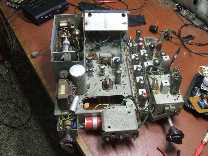
Above the chassis. The frame hold pot has been replaced, along with
the line output transformer, the frame blocking oscillator transformer,
and the volume/brightness switch pot.
Finishing touches.
The tuner mounting bracket was readjusted
so the channel knob lined up in the front panel hole. It's easy to see
why it had moved, as it's a natural reaction to lift the chassis by that
corner. The insulating bushing was missing from one of the back of the
chassis mounting screws. I replaced it with bushings intended for power
transistors. It would not have been a shock hazard without it, as the bracket
that the screw goes into is not accessable from outside the cabinet, but
it looks better to have things correct.
Chassis reinstalled. The now unused EHT condenser is visible right
at the top right mounted on the CRT bracket.
Now let's look at the circuit.
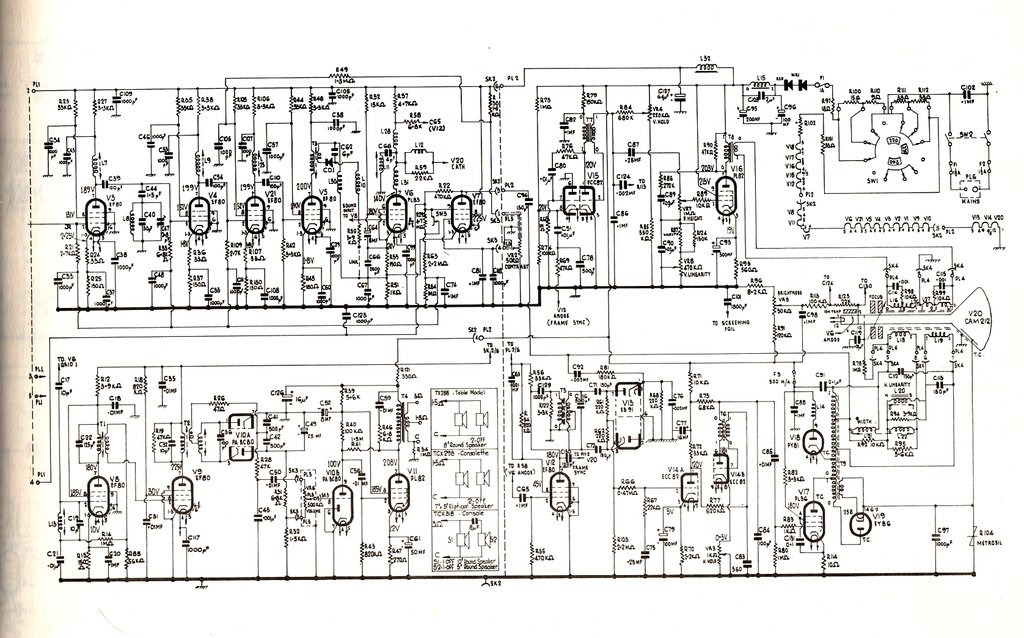
Video stages.
The IF from the tuner is fed into the
video IF strip based on four 6BX6's (EF80's), tuned to approximately 36Mc/s.
"Approximately" because stagger tuning is used to obtain the necessary
bandwidth. Unlike most other sets, the Ekco uses single tuned IF coils,
rather than double tuned transformers, to couple the stages. This makes
alignment very easy, and it can be easily done without a sweep generator.
A germanium detector diode feeds the 15A6/PL83
video amplifier pentode in the normal way. DC coupling is used, so bias
for the PL83 is dependent somewhat on signal. The plate of the PL83 is
also DC coupled to the picture tube cathode. The picture tube is a CRM212.
CRM presumably stands for "Cathode Ray Mazda", and 21 being the size. It's
a 21" 90 degree magnetic focus tetrode tube. The original used a bent gun
with ion trap, but the new replacement has a straight gun with no ion trap;
the screen aluminising protecting against ion burn. To fit in with the
series heater circuit, the heater is 12.6V at 300mA.
AGC.
AGC is of the gated type, using V7, 6BX6,
as the AGC rectifier and control. V7 operates as a variable shunt rectifier
diode which develops negative voltage from pulses obtained from the line
output transformer. Video signal is fed into the cathode of V7, as a grounded
grid amplifier. However, because the plate voltage appears at line
frequency, it means the valve conducts during the portion of video signal
when the line sync pulse is present. Thus, the strength of the line sync
pulse determines valve conduction, and thus the negative DC developed at
the plate. This DC is filtered and fed to the grids of the IF and RF amplifier
valves. A voltage divider is used to give greater AGC voltage for the RF
amplifier, than for the IF amplifiers. 6BX6's are sharp cut off valves,
so applying too much negative voltage will cause distortion. Note the presence
of a local/distant switch. In the local position, the IF valves are
given greater AGC voltage.
Contrast control is via the AGC, rather
than the video output stage. The contrast pot alters the overall conduction
of V7 by controlling its grid voltage.
Sync separator.
V12, another 6BX6, is operated without
any initial bias. Its grid is fed with the high amplitude video signal
from V6's plate. This causes V12 to produce a distorted video signal at
its plate. So distorted that only the sync pulses are produced here. From
the plate of V12, the sync pulses pass to the frame and line oscillators.
Frame oscillator and output.
The frame oscillator is of the blocking
transformer type. It's based around pins 1,2, and 3 of V15, a 12AU7. Some
degree of frequency control is available by controlling the grid voltage.
Unlike most sets, the B+ for the oscillator stage comes from the normal
230V B+ and not the B+ Boost which is usually around 500-600V. Pins 6,7,
and 8 of V15 are wired as an interlace diode. Interlace diodes are
probably unfamiliar unless you are familiar with 405 line TV receiver design.
Outside of British designs you're unlikely to see them. With the 405 line
system, loss of interlace causes a very obvious line structure to appear.
This is because the lines pair, giving only 202.5 lines. Hence, some care
had to be taken to ensure clarity of the frame sync pulses to ensure good
interlace. Good interlace can be upset by the entry of line pulses into
the frame oscillator. One way this can happen is via stray coupling due
to wiring and component layout, and even because of the magnetic coupling
between the line and field windings of the yoke. Another cause of the problem
is line sync pluses getting to the frame oscillator. And it's here the
interlace diode is used. Sync pulses are coupled into the oscillator via
the diode, but once the oscillator is triggered, the diode is reverse biassed,
thus preventing any of the line sync pulses getting through during the
frame scan. Line sync pulses are of course transmitted during the frame
sync period.
As the TCX-298 is for 625 lines, poor
interlacing is not so obvious, but it's obviously good practice to include
the interlace diode.
The output stage is a conventional pentode,
V16, type PL82. It has the usual waveshaping components to provide the
required sawtooth current in the scanning coils. The height control is
just a voltage divider controlling the incoming sawtooth amplitude, while
the linearity control adjusts the feedback.
Line oscillator and output.
V14B, 12AU7, is another blocking oscillator,
except of course optimised for 15,625c/s. Like its frame oscillator counterpart,
grid voltage sets the exact frequency. User adjustment is provided by a
pot in the cathode circuit. V14A is simply a DC amplifier which feeds the
grid of the line oscillator with DC proportional to the AFC detector voltage.
As is usual, an AFC circuit is provided
so that the line oscillator is not directly triggered from the sync pulses.
If this is done, it is possible with a noisy signal to have a jagged effect
on the outline of the picture, as the line oscillator triggers from noise.
Instead, an AFC circuit with a long time constant effectively filters out
the noise.
This is based around V13, a 6AL5 dual
diode. If it looks reminiscent of an FM detector, thats because it has
a lot in common. The 6AL5 is fed with line sync pulses via a coupling transformer.
It is also fed with sawtooth pulses from the line output transformer. Essentially,
if the line oscillator is out of phase with the sync pulses, a positive
or negative correction voltage is developed which controls the line oscillator.
C75 provides a long time constant so that interruption of sync pulses for
a few lines will not affect the overall oscillator frequency.
The line output valve is a PL36/25E5.
The output stage is conventional using an autotransformer. The damper diode
is a PY81. Originally, a 6S2/EY86 was used for the EHT rectifier, but with
the locally made Telecomponents transformer, a more common 1S2 is used.
One unusual feature, as far as Australian set design goes, is the EHT regulation.
Here a Metrosil VDR is shunted across the rectified EHT supply. As the
EHT rises, the Metrosil conducts more, drawing more current, and thus loading
down the EHT. Conversely, if the EHT drops, the Metrosil conducts less.
There is also a 1000pF EHT filter condenser. This is not required with
modern picture tubes due to the extra conductive coating on the back of
the glass.
Sound stages.
Returning now to the video detector, a
portion of signal is taken via a 10pF condenser to the sound IF amplifier.
As well as the video signal, present at the output of the video detector
is also a 5.5Mc/s sound signal. This comes about because the vision and
sound carriers are always 5.5Mc/s apart. The output of the tuner consists
of the video signal centered on 36Mc/s, and the sound on 30.5Mc/s. When
both of these are fed into a non linear stage (e.g. detector diode), the
sum and difference frequencies are produced. Hence, 36-30.5 = 5.5. The
sound IF amplifier is V8, another 6BX6. Its input and output are tuned
to 5.5Mc/s. Following this is V9, the limiting stage. Important in an intercarrier
sound system is AM supression. This is because the vision carrier (AM)
effectively functions as the local oscillator in the 30.5 to 5.5Mc/s conversion.
V9 operates under non linear conditions, rather like the sync separator.
Again, it is provided with no initial bias. This means that any AM is clipped
from the plate signal. Note that the grid of V9 actually produces a negative
voltage to control the gain of the sound IF amplifier. Therefore there
is a degree of AGC for the sound IF. This is unusual.
Sound detection is by a conventional ratio
detector, using the diodes of a 9AK8/PABC80. The triode of this valve functions
as a conventional amplifier which feeds the output valve, a PL82. Negative
feedback is provided by a 1.5M resistor from the PL82 plate to its grid.
A form of frequency correction is provided by the RC network across the
output transformer primary. Because of the live chassis, the output transformer
must also provide mains isolation. The speaker voice coils are connected
to the chassis via a 1M resistor; high enough not to pass a dangerous current,
but sufficient to discharge any static build up on the speakers.
Power supply.
The valve heaters are connected in a series
300mA circuit. Depending on mains voltage, various resistors are connected
in series to accomodate for the total heater voltage.
Warm up surge protection is provided by
an NTC thermistor. The mains is also rectified, originally by a selenium
rectifier, to provide B+ of about 230V DC. This is filtered by two chokes;
one for the deflection stages, and the other for the rest of the set. Across
the choke which filters the deflection stage supply is a 2uF condenser.
This tunes the choke to 50c/s for improved ripple rejection. Filtering
is of course more difficult when half wave rectification is used.
Because of the live chassis, a polarised
mains connector is used. This to hopefully ensure the chassis is always
connected to the neutral. Of course, one cannot always guarantee this because
of incorrectly wired power points and extension leads (live/neutral polarity
was not even officially standardised in 1957). So, the normal procedure
for servicing is to use a neon screwdriver to see the chassis is not live,
or better still is to use an isolating transformer. Because of the DC component
created by the half wave rectifier, it is necessary to use a transformer
larger than first thought. This is because the DC flow causes core saturation
and heavy losses. I use a 500VA rated unit, but 250VA would probably suffice.
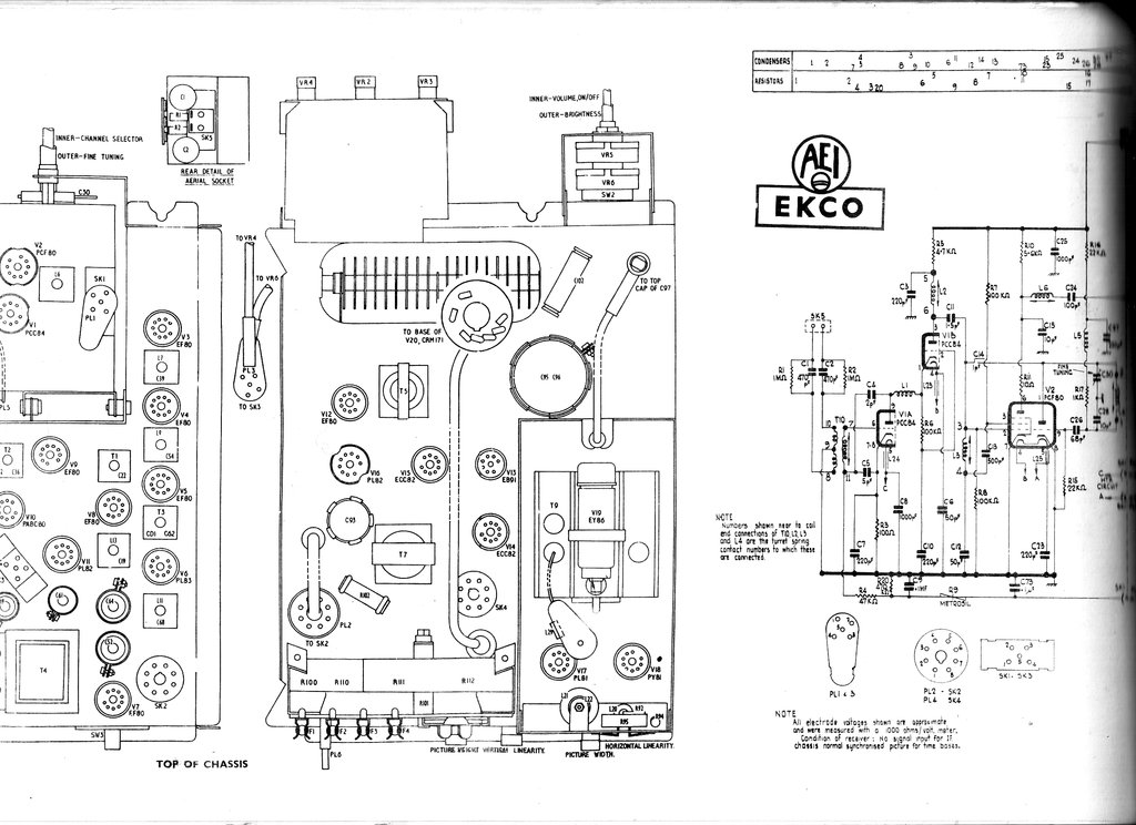
Tuner.
To the final part of the description,
the tuner is a conventional 12 position turret type. Fitted biscuits as
the set left the factory were for channels 1,2,6,7,8,9, and 10.
The aerial is fed into the RF stage via
the isolating components mounted on the aerial socket. The 470pF condensers
have a high reactance at 50c/s, so provide mains isolation, but at VHF
the reactance is low, so the signal passes unimpeded. 1M resistors discharge
any static build up on the aerial.
The RF amplifier is a conventional cascode
type, using a PCC84/7AN7 twin triode. Interestingly, there is another Metrosil
in series with the AGC to the RF amp. It provides AGC delay so the tuner
is not desensitised on weak signals. From here, the VHF signal passes to
the mixer, using the pentode section of a PCF80/9A8. The local oscillator
is a conventional Colpitts type using the PCF80 triode.