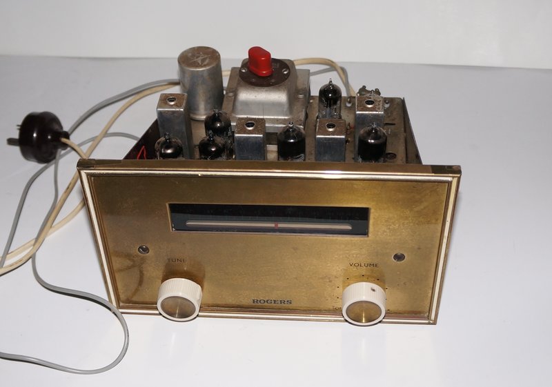
This tuner is the one described in this article.
This tuner is the one described in this article.
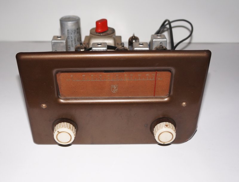
This tuner was missing part of the tuning unit and was not restored.
These two FM tuners came to me via an HRSA
member who wished to offload them. Being valve FM, I could not say no.
Until now, I had always thought that Rogers was a Canadian company, but
it turns out there was an English company of the same name, as evident
by these tuners. Apart from the 200-250V mains supply, the components were
obviously English, and all the valves have European type numbers. Interestingly,
however, the dial scale shows the upper frequency limit as 107.5Mc/s. This
suggests the tuner might have been designed with export in mind, since
the FM band in Europe and the UK was limited at the time. One English tuner
I have of similar age has an upper limit of 100Mc/s, and later ones are
104Mc/s.
The two tuners are identical, except for
the front panels. All that I could find concerning Rogers FM tuners was
a couple of circuits here
designated MkII and MkIII. They were obviously later designs, which suggests
what I have is the first version.
The design looked simple enough with a straightforward layout of components. Permeability tuning is used, which is typical of European design, but unfortunately, the tuning cores were missing from one of the tuners. With no circuit diagram, it was necessary to trace it out.
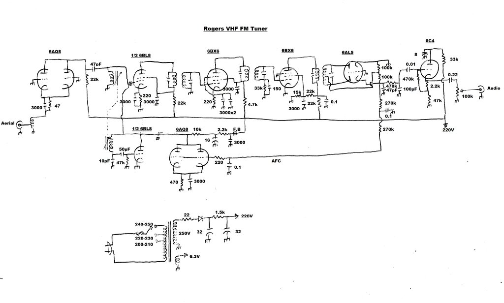
It turned out to be a completely standard 1950's era circuit, with the only strange thing being the 6AQ8/ECC88 valves being operated with both sections in parallel. They could have eliminated one of the 6AQ8's, but perhaps they were looking to increase the valve count! The receiver is not apparently intended for long distance reception, having an untuned RF amplifier, and only one IF amplifier stage, instead of the usual two. This was confirmed when it was tested.
The first 6AQ8 functions as a grounded grid RF amplifier, with both triodes in parallel. The aerial is fed into the cathode via what appears to be an untuned impedance matching coil. This is enclosed in an aluminium can, so I did not open it to examine the exact construction, but from other circuits I've seen it's likely to be as shown. The plate load is a 22k 1W resistor. This is higher than I've seen elsewhere; normally this resistor is 10k or less. The gain of this stage would be very low, if anything, and would mostly function to isolate the aerial loading from the mixer input tuned circuit.
The converter uses a 6BL8/ECF80 with the
pentode as the mixer. The grid circuit is tuned to the receiving frequency,
and
coupled to the RF amplifier by a 47pF condenser. The 6BL8 triode functions
as the local oscillator, operating 10.7Mc/s above the received frequency.
Its signal is injected into the mixer
grid with a 'gimmick' capacitor of a few pF. This is just a length of insulated
wire wrapped around the connection between the RF amplifier and grid.
The IF amplifier consists of a 6BX6/EF80 pentode operating at 10.7Mc/s. It then feeds a limiter stage using another 6BX6. Here, the screen voltage is reduced by means of the voltage divider consisting of a 22k and 15k resistor. The valve also operates with no bias, and there is a grid leak circuit. All these things cause the valve to clip at a certain signal strength, so as to eliminate noise from the received signal. Not shown are gimmick capacitors connected at the IF transformers between the plate and grid terminals. These would provide some degree of top coupling.
From here, the clipped 10.7Mc/s IF feeds a Foster-Seeley FM detector to provide the demodulated audio. De-emphasis occurs by virtue of the 470k and 100pF. This another noise reducing feature of the FM system. It's effectively a low pass filter which reduces high frequency noise, in much the same way a tone control set to the bass position can reduce noise of old recordings, etc. Ordinarily, this would also cause loss of the treble component, but at the transmitter this is increased by the same amount (pre-emphasis) so as to compensate. The end result is a flat frequency response, but with reduced high frequency noise.
Tuner before resistor and capacitor replacement.
The audio signal then proceeds to a 6C4/EC90
cathode follower. This has no voltage gain - in fact the gain is slightly
less than one, but it has a low output impedance. This allows the tuner
to work into amplifiers of varying or low input impedance without upsetting
the detector.
A volume control is provided between the
cathode follower output and the shielded cable to the amplifier.
Automatic Frequency Control is provided using another 6AQ8 with both triodes connected in parallel. This is connected across the 6BL8 triode. As the grid voltage changes, so does the capacitance of the 6AQ8. Since the output voltage of the detector varies with tuning, this can be used to provide AFC. The audio is filtered out by the two 270k resistors and two 0.1uF condensers. The filtered DC then feeds the 6AQ8 grids via a 220R resistor.
The power supply is conventional with a
transformer accepting 200 to 250V mains. The 250V secondary feeds a half
wave selenium rectifier which provides 220V after filtering. B+ current
consumption is about 26mA. There is also, of course, a 6.3V winding for
the valve heaters. A fuse is provided for the primary. It is located in
the voltage change plug - the voltage change panel being mounted on the
top of the transformer.
I noticed that the selenium rectifier
had been bypassed with a 1N4007 silicon diode and a series 430R 5W resistor.
It would seem someone thought the selenium rectifier was faulty. However,
it already looked like it had been replaced (new mounting holes).
No attempt had been made to clamp the
mains cable. This is made worse by the tagstrip it is connected to being
secured only at one end. At least a knot could have been used. Looking
through English electronics magazines, I note a lack of cable clamping
with many projects described therein. The other tuner, which appears to
be slightly later, did have a knot.
Getting It Going.
Since one of the tuners was missing part
of its permeability tuning unit, only the complete one was repaired. The
other one may be rebuilt to take a variable capacitor tuning circuit, or
it may just be used for parts.
At initial power up, it did provide signals
but they were weak, and sensitivity was poor. Checking a few resistors
revealed the expected fault of most of them being high. The first thing
was to replace the necessary resistors and then check the operation. It
was marginally better, but there were two paper condensers still present.
The 0.01uF in the cathode follower feed, if leaky, would upset the detector
by feeding DC back into it. This would also of course upset the AFC. Indeed,
it was found to be leaky and was replaced. The 0.22uF in the output feed
was of course also leaky, and was replaced.
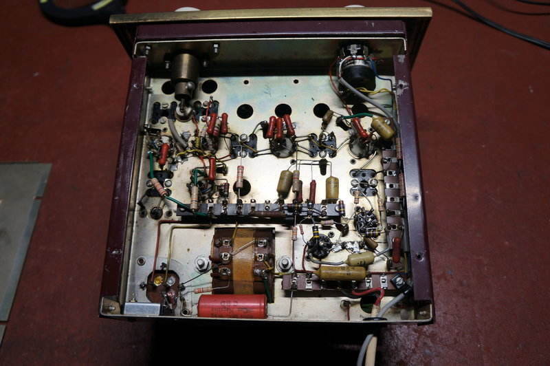
New resistors and capacitors improved performance.
Performance was improving but still not very good. Alignment was then checked and found to be way out. First thing to do was to connect a 10.7Mc/s FM signal to the grid of the 6BL8 pentode and adjust the IF and detector transformers. This made a huge improvement, but the front end was still out of alignment. It was not possible to cover the full band, and the dial calibrations did not line up at all. This is due to the local oscillator. If the oscillator core was set so the 87Mc/s end could be received, the highest frequency receivable was about 104Mc/s. Conversely, if it was set to receive 107.5Mc/s at the top end, the low end couldn't tune much below 90Mc/s.
The Tuning Mechanism.
Two vertically mounted coil formers are
mounted on the chassis for the RF and local oscillator circuits. Into both
these are inserted ferrite slugs mounted on a cross arm. As the arm is
raised or lowered, the slugs move in and out of the coils, thus changing
the inductance.
The arm is spring loaded so the natural
position is for the slugs to be at the top of the coils (least inductance).
A nylon cord wound around the tuning control shaft brings the arm in as
the shaft is rotated. The shaft is actually fed via a reduction mechanism
mounted on the front panel, to which attaches the tuning knob.
Unfortunately, there are no trimmer capacitors
as such, and the calibration of the RF and local oscillator circuits is
very dependent on how the coils have been wound, and the diameter of the
shaft pulling in the tuning arm. While elegant from a mechanical point
of view, the problem was difficulty in aligning it! There is a gimmick
capacitor in the local oscillator plate circuit, which is an earthed insulated
wire wrapped around the plate connection between the 6AQ8 AFC valve and
the 6BL8 triode. Even unwinding this completely gave only a minor improvement.
Perhaps the oscillator coil (or the 10pF and 50pF capacitors inside) was
faulty. I substituted the coil from the other receiver, and now it was
possible to get almost complete band coverage. It wasn't possible to get
the dial calibrations to line up across the whole band, but for the most
part they were fairly close. Around the 104-108Mc/s end of the band there
was a noticeable non linearity in the tuning.
Next, the RF core was set for maximum
gain at the low end of the band. Since there's no trimmer capacitor, the
loss of tracking at the high end of the band is unavoidable. Indeed, the
sensitivity does drop off.
Power Supply.
Curious about the need to bypass the selenium
rectifier, I actually tried it, and the B+ wasn't much less than with the
silicon diode. Thus, the circuit was restored to original. The other receiver
had a 22R anti surge resistor in series with its rectifier, so the same
value was used in this one. However, the B+ seemed a bit low (155V after
filtering), considering the rectifier input was 250V. This was simply a
result of a faulty first filter condenser. Connecting a modern 47uF in
its place brought up the B+ to 220V, which is what would be expected.
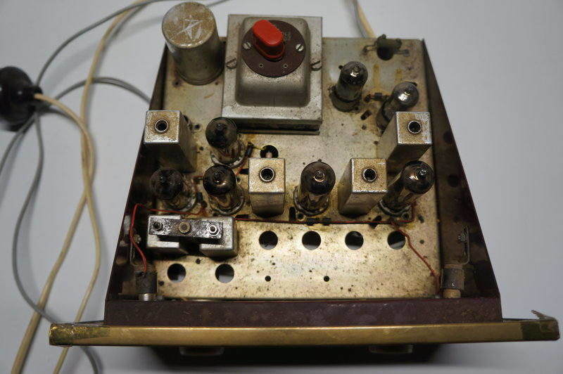
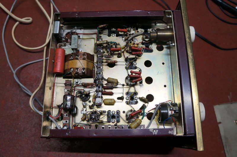
Top view of chassis. Tuning unit is at bottom left.
How Does it Perform?
In view of a crude RF amplifier stage
with no real gain, and only one IF amplifier, it's definitely not a DX
set. In fact, sensitivity is quite poor compared to a one valve super-regenerative
set. On the positive side, the sound quality is quite good with strong
signals. In fact, the audio output is quite high, at around 2Vp-p.
Tuning is awkward since it is so broad;
this being in part due to the AFC circuit. Distortion is noticeable on
weak signals. Even with a strong signal, if the tuning is not 'just right'
distortion is also evident - and the AFC does not seem able to correct
this. The distortion is clearly visible with the output fed into a CRO.
Just for fun, I got out one of my Meck
FM converters and I have to say, that apart from the lack of hi-fi
quality, the selectivity is better, and with a good aerial do provide surprisingly
good audio. There's an irony having a receiver with only one valve being
more sensitive and easier to tune than one with seven valves, but the trade
off is the Meck having a noisy output on weak signals, and of course the
super-regenerative quench beat with the audio signal sometimes being evident.
The way I see it, the Rogers would have satisfied the local station hi-fi listener back in the 1950's, but that would be all. The permeability tuning unit is in dire need of sufficient adjustment, to allow it to be set for proper band coverage and tracking. An extra IF stage should have been included. As it is, I may well rebuild the limiter stage to operate as an IF amplifier. The AFC circuit seems ineffective, and this could be due to detector alignment. In fact the question of alignment is to be considered here, because I found with certain adjustments, the IF stage would break into oscillation. This suggests there is some regeneration occurring, which would reduce bandwidth and thus increase distortion. In fact, I found the best alignment for a weak signal did not suit a strong signal, and vice versa. The top coupling capacitors connected to each of the IF transformers may have something to do with this. I find their inclusion strange. Ultimately, I would need to run a sweep generator over the IF amplifier to see what exactly effect they have.