New winding under the white tape.
Some of the items listed have been repaired without any circuit diagrams available. A point that may be of use is that when servicing equipment that uses IC's and you have no circuit, get the IC data off the internet. Generally, the circuits around the IC will be very close, if not identical, to the examples provided in the data.
HP 1702 LCD monitor stays on for a few secs after power up then goes blank. LED stays green but no image. Shine a torch into the screen to verify it's just the backlight gone off. Replace the 100uF 400V filter capacitor fed by the mains rectifier. Cap tests OK in terms of capacitance, but ESR is too high causing supply voltage to drop under load (i.e. when the backlight comes on).
On a separate issue, why do manufacturers continue to use .47uF and 1uF electros? These are notoriously unreliable, especially in switchmode power supplies. An MKT type has lower ESR, temperature stability and fits in the same space.
Dreambox 7025 satellite receiver. Power supply: 12V standby suppy working but main supply starts up for a fraction of a second. Replace all the electros on the primary side. Because of heat, they have all gone low in value. Fortunately, this doesn't seem to be a design that self destructs when this happens. Use an MKT for the 1uF replacement. To activate main supply, connect first two pins of multipin plug together with 10K resistor. 1st pin is 12V all the time (standby) & 2nd pin is the power control. Electros near heatsinks are a recipe for problems. I recommend a fan be installed for anything that has a switchmode supply that runs hot.
HP D530S desktop PC. Major
production fault in the power supply. If the computer is unplugged from
the mains for a while (~few weeks), the PSU will blow up when next plugged
in. The problem is the brown glue around the main switching FET becomes
conductive and absorbs moisture when the power supply has cooled down (i.e.
when not plugged in). Being a high impedance device, the FET doesn't
need much leakage between its gate and drain terminals to switch on, which
it happily does so upon next power up, discharging the filter electro through
itself and the control IC. The 22R also blows.
If you have one of these computers, remove
all the brown glue on the power supply PCB while you still have a working
PSU. Either that, or never turn off at the mains.
LG RH1777 DVD/HDD Recorder.
Theben time switch. This DIN rail mounted 240V time switch had no display. The supply for the relay is about 35V DC which is obtained from a .15uF dropper capacitor and bridge rectifier. From this 35V supply, a supercap is charged to about 3.7V to drive the clock. No 35V supply was present, but everything worked when external DC was fed into the filter cap on the DC side of the bridge rectifier. There is a .1uF surface mount cap on the AC input of the bridge. This was s/c.
Dick Smith and Jaycar Inverters.
Sanyo VTC9300 Betacord VCR.
JVC HR3660 VHS VCR (HMV
HV3000). Intermittent tape loading, FF & rewind, even
though heads spin etc. Gradually gets worse. The two main flat drive belts
are slipping. The loading up functions and reel drive are done by the motor
just to the right of the cassette housing. If you see the pulley spinning
but the belt not moving, that's the problem. This belt drives another pulley
which reemerges on the underside of the chassis to drive a second flat
belt. This may also be slipping. Generally, mechanical things not happening
are belt related in this model. Once or twice belts have come off due to
a jammed tape. The reliability of these machines is incredible. These are
from 1980, and out of both of mine, have only had to replace a few belts
(once), a cassette lamp, and an RF amplifier IC after a storm.
JVC HR7700 VHS VCR (Telefunken VR540, Akai VS10, Rank Arena RV330).
Early VHS and U-Matic VCR's,
Various Models. No tape functions. Check the cassette lamp. If
this goes open circuit, the microprocessor shuts down disabling mechanical
functions. The cassette lamp is used to sense the end of tape (transparent
leaders). Later VCR's use IR leds instead of an incandescent bulb.
If the machine seems to randomly shut
off when servicing, see that any room lighting or sunlight is not striking
the optical sensors. I recall one JVC CR6060 U-Matic that would shut off
in the morning when looking for a totally unrelated fault. The sun was
coming through the window at a particular time, striking the opto sensor
which made the machine think it had got to the end of the tape. Betamax
machines detect metallic leader tape and do not exhibit this problem.
Crompton PIR sensor switch.
Fault was that although the light could
be switched on by a rapid turn off and turn on of the supply, in the usual
way, the PIR part was non functional. I took the LDR out of circuit so
that it would think it was night and thus function with ordinary room lighting
whilst working on it. Tried changing the LM324 first. Touching the back
of the PCB actually made it work, so it was obviously a resistor gone high.
The 100K resistor next to VR1 had risen to 245K.
Fisher & Paykel GW508 washing
machine motor controller (phase 4).
The 15.5V power supply had blown up; more
specifically, the TOP224Y switchmode IC, the P6K200E transient suppressor
diode, and what appear to be the zener diodes for the error control. Of
course, the 4A fuse had blown also. For those not au fait with these machines,
F&P use a three phase stepper motor rather than a conventional induction
motor and gearbox. This allows an extremely high spin speed, etc. The stepper
motor is switched by MOSFETS fed from 340V DC (rectified and filtered 240V
AC). The 340V DC also feeds the switchmode power supply that provides 15.5V
for the control circuit and solenoid valves. The pump is conventional and
is switched by a Triac from the 240V AC supply. So, it can be imagined
that any spikes on the mains can easily destroy the motor controller. A
novel feature is that the MOSFET heatsink is water cooled. Incoming water
to fill the tub is circulated through a length of aluminium tubing to which
the power semiconductors are clamped.
First point of call was to feed 15.5V
from a bench supply into the controller - it actually looked very promising
with LED's lighting up and the buzzer doing its start up sound. None of
the motor switching MOSFET's tested short circuit. Given the time taken
to get the parts to repair the 15.5V supply, and that it would still be
a typical vulnerable SMPS, the decision was to make an external linear
supply to provide 15V. The damaged parts were removed and also the switchmode
transformer. A 15V 1.2A transformer, rectifier, fuse, 3300uF cap and 7815
regulator assembled in a plastic box did the trick. Wires were run out
of the motor controller to the new black box secured to the back of the
machine. Complete success.
Note that the 15.5V circuit is all live
at mains potential. Therefore the external power supply must be completely
insulated and connecting wires rated for 240V AC.
I replaced the 4A PCB mount fuse with
an M205 fuse. It just so happens the PCB allows the use of an M205 fuseholder.
Also note the PCB is covered in a plastic layer - I used 3M clear protective
coating to restore this. With 340V DC circulating, it won't take much leakage
to destroy something.
While these F&P machines give an excellent
wash and have a fantastic fault diagnosis system, they are unreliable and
the internet has many stories of problems. This particular machine has
over the last few years had the pump, lid switch, hot solenoid valve, and
balance switch replaced. Luckily these parts are cheap on ebay. It was
only a matter of time before something went wrong with the yellow box...
I would advise these machines to be unplugged
from the mains when not in use - the SMPS operates and 340V DC is present
while ever the mains supply is on. A surge protected power board is also
a wise idea.
Motorola Razr V6.
This phone would not recognize the SIM
card. A close look revealed what looked like dry joints on at least one
of the SIM card contacts. Resoldering these fixed the fault. The service
manual is available on the internet which describes how to dismantle the
phone.
AWA Line Output Transformers.
The type referred to was used by AWA from the mid 1960's in monochrome
TV sets until the last P1's in 1973. These have an additional winding for
the horizontal AFC circuit. This AFC winding can short to the main primary
winding, and since one side of the winding is earthed, the 6AU4 plate glows
red and excess B+ current is drawn. The repair is first to disconnect the
AFC winding and let it float at the primary voltage. At this stage, the
EHT and line output should be restored to normal.
Next, wind on a new AFC winding one one
side of the transformer core to produce 350Vp-p. See the service manuals
on where to measure this. It will need to be phased correctly or the line
oscillator will not lock. I used 0.3mm enamelled copper wire. Wind a layer
of tape around the core first for insulation. These transformers operate
with about 7Vp-p per turn, so 50 turns are required for 350Vp-p.
This repair done to a P9Z chassis has
lasted 25 years at the time of writing. As an interesting thought, it should
be possible to simply do away with the AFC circuit and directly inject
the sync pulses into the line oscillator. Since there are no off air transmissions
now, there does not need to be the noise immunity provided by the AFC circuit.
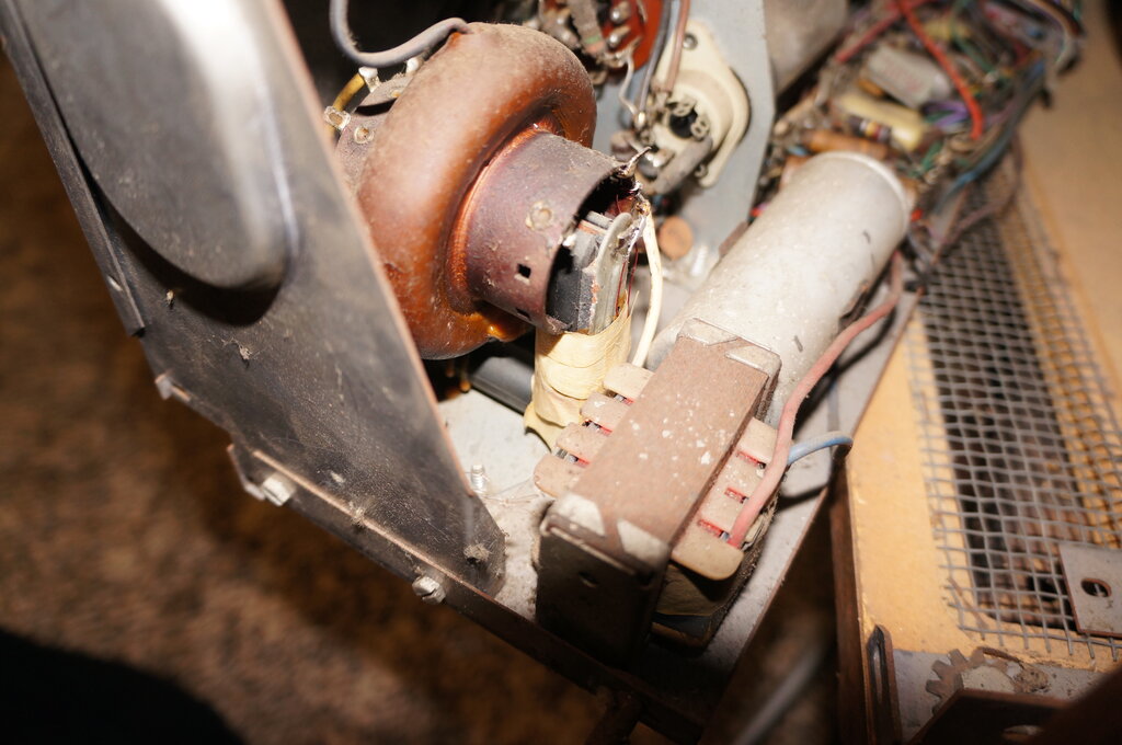
New winding under the white tape.
Sony SL-C7 Beta VCR. (September 2021)
KRK Rokit 10-3 Powered Monitor
Speaker. (September 2021)
Blown fuse. Switching FET S/C. (No surprises
there). Carbonised insect found between the gate and drain pins. The driver
IC was unknown and a likely type was chosen for replacement. It required
modification to the circuit to make it work. Note that the main filter
electro remains charged at 340V even when not powered up from the mains
and is a hazard when servicing it. There is nothing to discharge it. Use
a light bulb to discharge it before working on it. See the video here for
more details: https://youtu.be/hMdYD7gMOPA
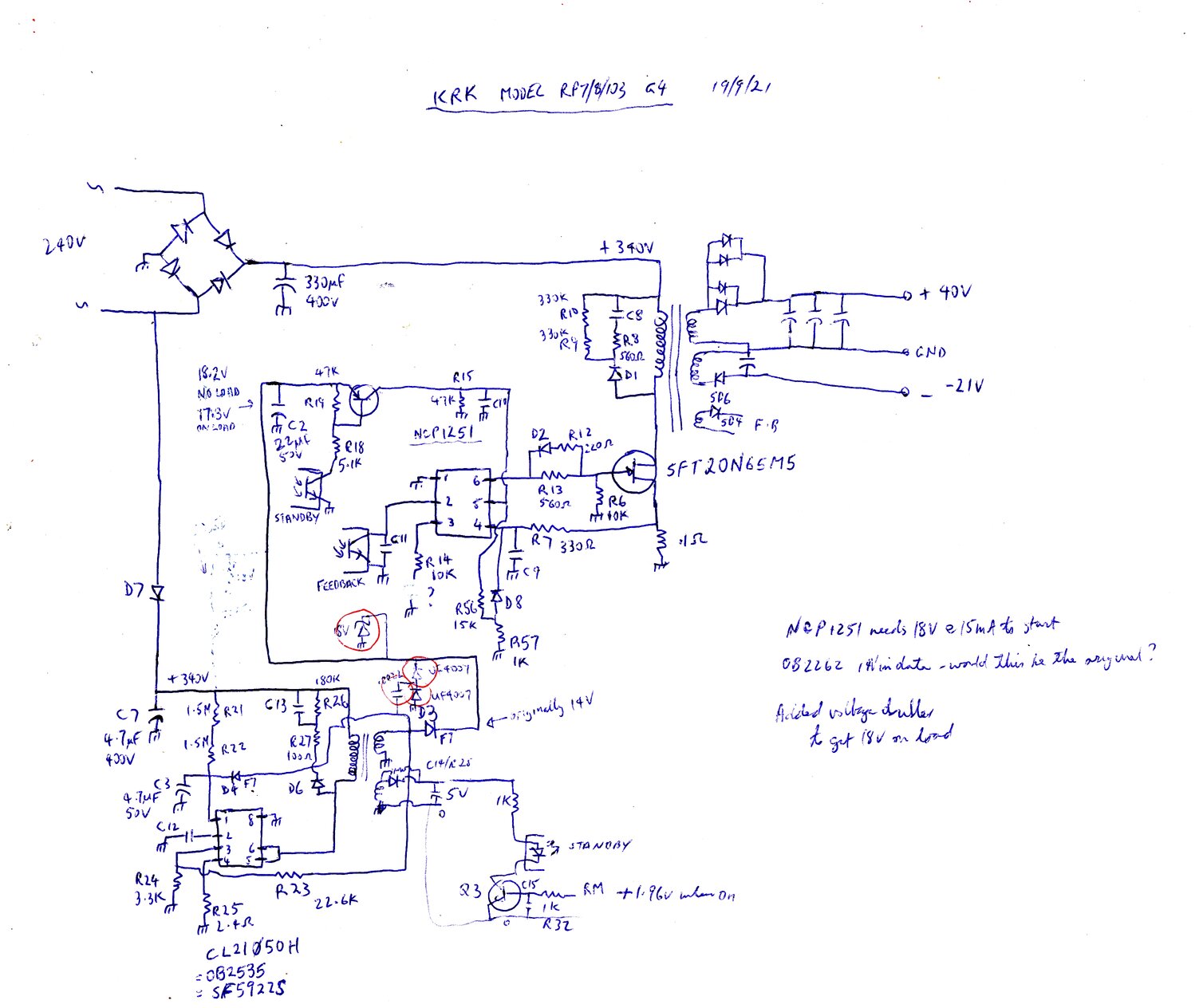
The IC which drives the main power supply
is not the original type since the type number was not visible. The substitute
used (NCP1251) had the same pin connections and functionality. However,
the original IC has a 14V supply. The substitute was found not to start
unless its supply was 18V. To fix this, a voltage doubling rectifier was
added, consisting of two UF4007 diodes and a .0022uF capacitor. It is stabilised
by an 18V zener diode. Further searching of possible types suggested that
OB2262 might work since it has a 14V supply.
AVO VCM163 Valve Tester.
(20/10/2021)
Failure of the gm meter to show any reading.
The 500R pot RV1 was O/C. This is on the vertical pot panel. During the
repair it was noticed that R35 (2.4K) was burned and had doubled in value.
This resistor is mounted on the ma/V switch. Use a 22K//2.7K to get 2.4K.
There was a slow response from the gm
meter when the tester was first switched on, taking around a minute for
the pointed to come up to the "cal" marking. Replacing all the electrolytics,
.01uF, and two 0.47uF's on the amplifier board fixed that.
To get access to everything, remove both
side panels and the bottom panel. To get the bottom panel out, loosen the
screws holding the transformer chassis to allow the side frame to be spread
slightly. Don't undo the bolts surrounded by rubber.
Tektronix TAS475 CRO. (10/11/21)
Burning smell. There is a metalised paper
.047uF 300VAC X1 capacitor connected across the mains input before the
switch. Therefore, mains voltage is applied to it while ever the CRO is
connected to a live power point, even though it is switched off.
Remove the power supply and look for the
cap across the IEC input socket.
Tektronix 2712 Spectrum Analyser. The digital and sweep PCB's are loaded with surface mount capacitors which have started leaking and eat into the adjacent tracks. Unfortunately, replacing them has not fixed the fault.
Noisy 6M5 Valves. If your
6M5 equipped apparatus is making a scratching sound and has low ouput,
check what kind of 6M5 is installed. The original Philips production is
prone to silver migration between pins 1 and 2; these being the screen
grid and control grid pins.
These valves are easily identified because
they have the sharp silver plated pins, and the flat glass base is made
separately to the valve's envelope. Scrape and clean the silver migration
off the glass and all will be good again.
Rank Arena Tripler Replacement. 1970's era Rank Arena colour TV's use an expensive and unique tripler. Typical of set models are C2201, C2601, C2209, etc.
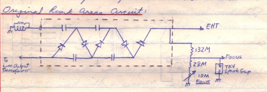
Above is the original tripler circuit.
EHT is connected to the CRT in the usual way, but also to a bleed circuit
which also supplies the focus voltage. This is a large tubular 132M resistor,
along with a 28M resistor and 10M focus pot. As well as supplying the focus
voltage, the bleed circuit provides a degree of EHT regulation.
An inexpensive and widely available Philips
tripler can be used as a replacement. Instead of paying $80 for the original
(not that you'd get one in the present day), a Philips tripler, or a clone
thereof, can be obtained for under $20. However, some alterations are required:
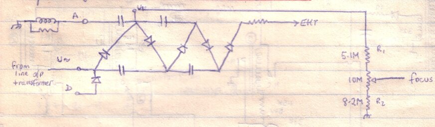
The Philips tripler has a focus voltage
terminal, labelled Uf. The Rank Arena focus circuit is modified to use
this, as it would be in other sets using this kind of tripler. The existing
10M focus pot is retained, but two high voltage focus resistors are added
as shown. Do not use ordinary resistors. They will simply not last with
8kV applied. If by chance, it is not possible to peak up the focus, swap
the position of the two resistors. At this point, EHT and focus voltages
will be obtained and the set will work. But, there is a problem in that
EHT regulation is poor, and the picture width will vary with brightness
- more so with 26" sets. One other thing has to be done:
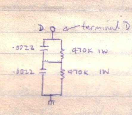
A clamping circuit is connected to terminal
D of the tripler. This clamps the negative pulse from the line output transformer,
and restores regulation by lowering the effective output resistance. The
capacitors are 630V rated. Alternatively, a 1000pF 1kV capacitor can be
used. The resistors are ordinary 470k 1W types. This extra circuit can
be built on a tagstrip and mounted near the tripler.
I have used this modification in many
Rank Arena sets since the late 1980's and it has been completely reliable.
GW (Good Will) GPS-3020 Power Supply. (26/11/21) Voltage adjustment working OK, but current control does nothing - current is always at max setting. DZ7 is a 5.6V zener and was short circuit. The current control does not use that which is already in the 723. Instead, it uses a two transistor differential amplifier, which operates on the 723 voltage control. One transistor base is fed from the current shunt (actually the 2N3055 emitter resistor) and the other transistor base is fed from the current control pot. The common emitter resistor is 3.3k and is fed from DZ7.
Cotek S150-224 Inverter.
(29/11/21). This 24V to 240V 150W inverter would run for 2 seconds and
shut down. With the inverter fed from 12V it would stay on. Surprisingly
it was still putting out 240V, but the waveform was more like a square
wave instead of the sine wave specified. It appeared that the under/over
voltage protection was set up for a 12V inverter, because it would stay
on from about 10V to 15V. With microprocessor controlled inverters, one
of the pins of the micro usually samples the supply voltage and shuts down
the inverter according to whatever voltage has been programmed into the
firmware. It seems that pin 18 of the PIC16F819 is used for this. If the
pin voltage rises to 2.17V, it shuts down. However, looking at the voltage
divider 56K + 10K, the voltage at this pin should be 3.63V with a 24V supply.
In order to make the inverter stay on, the pin 18 voltage could be reduced
by paralleling an 8.2K resistor across the 10K. Now, the inverter would
work at 24V and shut down at 29V. So far so good, except the under voltage
protection wasn't working. This seems to be detected somewhere else besides
pin 18, since pin 18 has no effect on this.
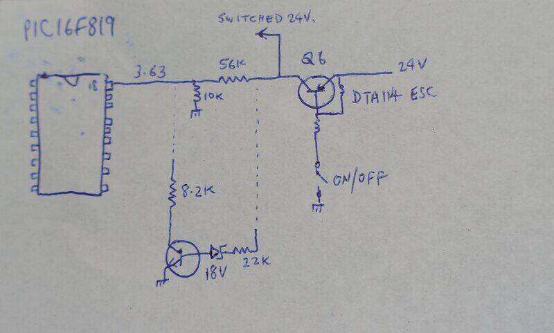
To enable to under voltage sensing to
work, the 8.2K needed to be removed from circuit when the supply voltage
got too low. An NPN transistor is used for this, along with an 18V zener
diode and 22K base resistor. When the supply drops to around 18V, the transistor
switches off, disconnecting the 8.2K resistor. Because the supply voltage
is still higher than 15V (the 12V shutoff voltage), the overvoltage protection
shuts down the inverter instead of the undervoltage. This has the same
effect - to protect the batteries from excessive discharge.
It would appear that something had corrupted
the firmware of the PIC chip, causing it to think it had the instructions
for the 12V model. The inverter was used in a area of frequent lightning
strikes and that's all I can put it down to.
https://youtu.be/-8cPd7PkAF8
Leaky Alkaline Battery - strange
PCB faults. (10/1/22). It is now common and expected that alkaline
cells leak, particularly size AA, and particularly Duracell. One internet
comment was leakage is more likely since mercury is no longer added to
the cells.
The alkaline liquid wicks along the negative
wire and onto the PCB. It then soaks in and causes electrical leakage.
In one instance, a Philips remote control for a 2BS TV set would operate
intermittently. In another more recent case, the MK484
receiver started to suffer from very poor selectivity and low gain
some time after it was discovered the AA cell had leaked. Nothing unusual
was visible, but if the receiver was taken into the sun, it worked very
well. Similarly, heating the area near the tuned circuit/MK484 input cured
the fault.
Once let to cool down the fault was back.
Closer observation showed the alkaline liquid had migrated along the entire
negative track of the PCB, which ran close to the MK484 input. Since the
MK484 relies on a high Q tuned circuit for selectivity, any extra resistance
in parallel ruins performance. The fault was fixed by connecting the tuning
condenser, aerial coil, and MK484 input pin in mid air.
IBM XT Computer (Model 5160).
(15/1/22). Memory fault at 192k during the POST. Error 30000 04 201. U78
RAM chip in bank 3 faulty. The computer still works once F1 is pressed,
but will not run programs that need the full amount of memory. Faulty RAM
chip was replaced with another of the same speed which restored operation.
Look for shorted tantalum capacitors on
the motherboard if the computer won't start up.
Pye "High Fidelity Stereo Theatre"
Radiogram. (26/06/22). Made in 1966, the amplifier uses 6CA4,
12AX7, 2 x 6GW8. Tuner is solid state with three transistors and two diodes;
all germanium. Intermittent fault with volume fluctuating when first powered
up. Severe distortion evident when volume dropped along with poor sensitivity.
1st IF transistor found to be unusually thermally sensitive, but the change
in volume was not as sudden as with the fault. Nevertheless, it was substituted
with a BC328. This being silicon required the 120k bias resistor to be
reduced to 100k. Fault still evident. Supply voltage to tuner found to
be very critical at 7.5 to 9V. Above 9.5V the low volume and distortion
was evident. However, the supply voltage remained at 8.6V even with fault
present. 2.5uF AGC capacitor had excess ESR and was replaced. Original
IF transistor returned to circuit, but 120k found high. Fault still evident.
It was noted that the ceramic capacitors
were all Ducon Red Top types. These have been noted for leakage in the
past. Replacing all fixed the fault. All but one found to be leaky. Supply
voltage no longer critical with tuner functioning normally beyond 15V.
Like most intermittents, the fault could not be induced at will, and a
lot of time was spent on this three transistor tuner.
Pye 12" T27 Portable TV. (26/06/22). No sound except at earphone socket. Speaker o/c. This is the third Magnavox speaker from early 1970's portable TV's which I've found o/c. The other two were in Thorn S1 chassis. Luckily, for this one, the break was in the wire running down the cone to the voice coil, and could be bridged.
AWA 11" P1 Portable TV. (26/06/22). Unstable line sync and AGC. Someone had already replaced the sync separator load resistor and other resistors in the line AFC circuit. Found video present at sync separator plate instead of clean sync. Video detector signal had lots of ripple and virtually no sync pulses. B+ checked and had considerable line ripple. 200uF in voltage doubler open circuit. The trick with this fault is there was no hum in the sound, and the raster was normal. For anyone repairing P1's, there are three paper capacitors to replace; the two .047uF boost capacitors, and the .0068uF in the frame oscillator. The high value IRC resistors are also suspect. Those remaining in this set were OK. Actually, this is one of the best P1's I've seen.
Sanyo CTP1601 Portable TV.
(26/06/22). This mains/12V portable colour set worked on 12V but not 240V.
A 500mA fuse was found blown, but replacing it did not restore operation.
Tracing the mains circuit, it was found that the 6 pin 12V input socket
should have a dummy plug inserted to link the 240V connections. This was
of course missing. A replacement was fabricated from cutting up a couple
of 4 pin speaker plugs, mounting them in a plastic bottle top and filling
that with car body filler. While it could have been possible to simply
link the pins at the back of the socket, this would be unsafe since there
is no isolation between the 12V and 240V supplies. Thus, if the 12V cable
was plugged in at the same time as the set was working on 240V, the cigarette
lighter plug would be live at 240V.
It is a strange set up with a separate
240V input socket. Other sets I have seen like this use the one multi-pin
socket for 12V and 240V, obviating the need for the easily lost dummy plug.
It would have been just as easy for Sanyo to provide a 4 pin male input
socket, with 4 pin female plugs wired for 12 and 240V.
Unless they have been in regular use,
most rotary UHF tuners have frozen up by now. This set was no exception.
The way these tuners work, the shaft is concentric with the knob turning
the steel shaft in the centre. By means of a vernier reduction inside the
tuner, the outer shaft rotates at a slower speed, and it is this which
drives the variable capacitor inside the tuner, and the dial via plastic
sleeve coupled to the outer shaft. When the tuner freezes up, the plastic
sleeve bonds to the steel shaft. It is necessary to remove the plastic
sleeve from the shaft. Remove the C-clip and squirt CRC down between the
sleeve and the shaft. It takes some time to free it up, but once the plastic
sleeve can be removed, it can be properly cleaned. Note that the dial drive
inside the tuner is secured only with a couple of soldered joints - so
don't force it.
Rohde &Schwarz SMS Signal Generator.
(4/08/22). RF output permanently off, with LED always on. Switch non responsive.
Check the overload protection PCB. This is in the line to the output socket
and in mounted next to the fan. Unplugging the 4 pin connector should restore
switch operation. If so, check the board for excess dust blown in by the
fan. It appears this can become conductive. The signal output from this
PCB should be 0V under normal conditions. In the faulty unit it was found
to be +3V.
The RF output on/off switching uses the
attenuator relays.
Philips MM2 "Philadelphia" Transistor Mantel Radio. (24/01/23). No sound except when left off for a long time. For something made in Australia, the construction of this set is a disappointment. It looks like it's made to a cost, and the assembly looks rather fragile. From the late 60's/early 70's, the design is based around two locally designed modules; a radio tuner, and an amplifier. Both of which found application in numerous Philips products of the time. Audio was present from the tuner, but no output from the speaker. The amplifier is a typical four transistor design, and output uses an AC188/AC187 complementary symmetry pair. The junction of the emitters should be half the supply voltage, but when faulty was around 12V (the supply voltage). Direct coupled amplifiers are a pain to service, because anything anywhere can upset the whole circuit. Also, in this instance, the wires were too short to allow the module to be worked on in situ. It has to be disconnected from the set and serviced externally. To make service more difficult, the components are crammed together with the resistors and capacitors stood on end. It was quicker simply to remove all components in one go and test individually. One 125uF electro was found to be leaky, a few resistors were high, but the main fault turned out to be the AC128 driver. It tested as a PNP transistor, but had no gain. Upon replacing it, the radio worked perfectly every time it was switched on. Aside from that, one of the 12V 100mA dial lamps needed replacement.
Philips MT5 Transistor Mantel Radio.
(27/01/23). This battery operated set looks like it was based on something
mains operated. There's a cord entry slot under the cabinet. There's no
proper battery holder, with the battery (276P) simply secured between the
cabinet back and the speaker frame. This set had a very low output. Blue
Philips electrolytics are alway suspect, and one was found to have excessive
ESR. However, replacing all electros did not make a huge difference. Ducon
red topped ceramic capacitors are another source of problems in that they
can have excess leakage. The ones in this set tested OK. The audio from
the diode detector was weak, which indicated the problem was before the
detector itself. The diode tested OK. Measuring the RF to the diode input
found that too was weak.
Probing with a signal tracer, it was found
the signal at the collector of the 2nd IF transistor (i.e. IF transformer
primary), was much stronger than on the secondary side feeding the detector.
Temporarily substituting another IFT (from a DSE L2060 coil kit) brought
up the volume by a noticeable amount. The volume was still inadequate on
anything but the powerful ABC stations, so the first IFT was also substituted.
The gain was considerably increased, and the performance was now acceptable.
Since the replacement IFT's do not have the same pin configuration, holes
had to be drilled into the PCB and tracks cut to install them.
Kleenmaid DW1 Dishwasher.
(Oct. 2023). Pump motor insulation failure due to worn seal. There is nothing
on the machine which identifies it as a DW1 and this was determined from
the sales brochure kept by the owner. Kleenmaid is/was an Australian
company, which had these dishwashers made for them by an unknown European
manufacturer. There is no parts backup for them. However, examining the
motor itself revealed it is a very common type made in Spain, and used
in a multitude of dishwashers never heard of here.
The type number is 2-102/FA10 which is
equivalent to Z401001 and LVC-21. With that establised, I found the motor
available in Australia from Bigwarehouse, and it cost about $170 all up
including postage. However, don't order it as a Kleenmaid part. You'll
save about $100 if you order it as Fagor dishwasher part.
Incidentally, the seal and impeller for
this pump is available from a few suppliers. Catering spares and gastroparts
are two such suppliers.
The motor run capacitor is 6uF. This machine
is on its third capacitor.
Decca 33 Hybrid Colour TV.
(10/1/24). Circuit breaker failure. Common fault is the circuit breakers
fail open circuit, and pushing the reset has no effect. Problem is the
plastic of which the reset button is made melts due to heat generated by
the contacts and bimetallic strip.
Therefore, it can't push in far enough
to reset. The button shaft where it enters the metal frame can be turned
down on a lathe to effectively restore its length. Unfortunately, these
circuit breakers are of very poor design, built on a flimsy piece of metal.
Problem is if the metal should bend, it throws out calibration. Be very
careful when opening and putting it back in its case so that the switch
shaft doesn't bind against the frame. The fibreboard base must be kept
perpendicular when reassembling. Rating appeared to be 1.4A on the set
in question, but another I had appeared to be 1.7A. It should be possible
to use a generic 1.5A thermal breaker as a replacement if the original
is not repairable.
As a general rule, most of the resistors, except wirewounds, need to be replaced in these sets. Frame oscillator locking/speed problems are also due to capacitors - replace the lot; ceramics, polyesters, etc. Snowy picture - replace all the resistors on the IF board. Constantly noisy height and linearity controls are best replaced with fixed resistors.
*The circuit breaker eventually failed permanently. A new 1.5A type was obtained from Ali Express (sold under the name '91 series').
AWA Television 207-C, 209-C, 211-T, 212-C. (June 2024). Retrace lines at top of picture can be removed by increasing the value of C318 to 0.1uF or 0.12uF. Sets with AC coupled video stages, such as these, are more prone to the problem since the CRT bias shifts depending on the picture content. The field blanking circuits were adequate for the time, but the problem appeared later on with the introduction of test signals, and later, Teletext, in the vertical blanking interval. If the retrace is slow, these peak white signals can be seen in the visible part of the picture. See my restoration of one of these sets here https://youtu.be/8oUOuy1UYpk
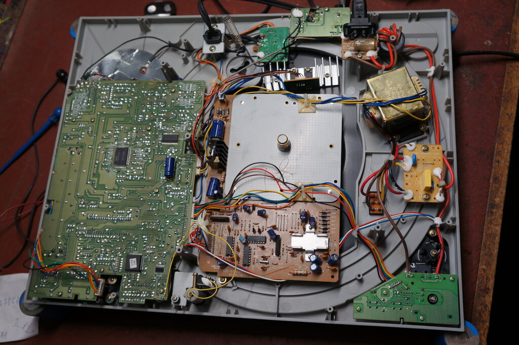
Harmon Kardon AVR2550 Receiver/Amplifier. (19/12/2024). The complaint was "no display". The 'soft' power switch did change from orange to green when pressed, but nothing else. Measuring the outputs from the power supply revealed nothing, and neither was there output from the large power transformer. It seemed no mains was getting to its primary. Examining the circuit showed the mains was switched by a relay. This is to be expected due to the soft power switch and remote control needing to be active at all times. This part of the circuitry is supplied from a small transformer.
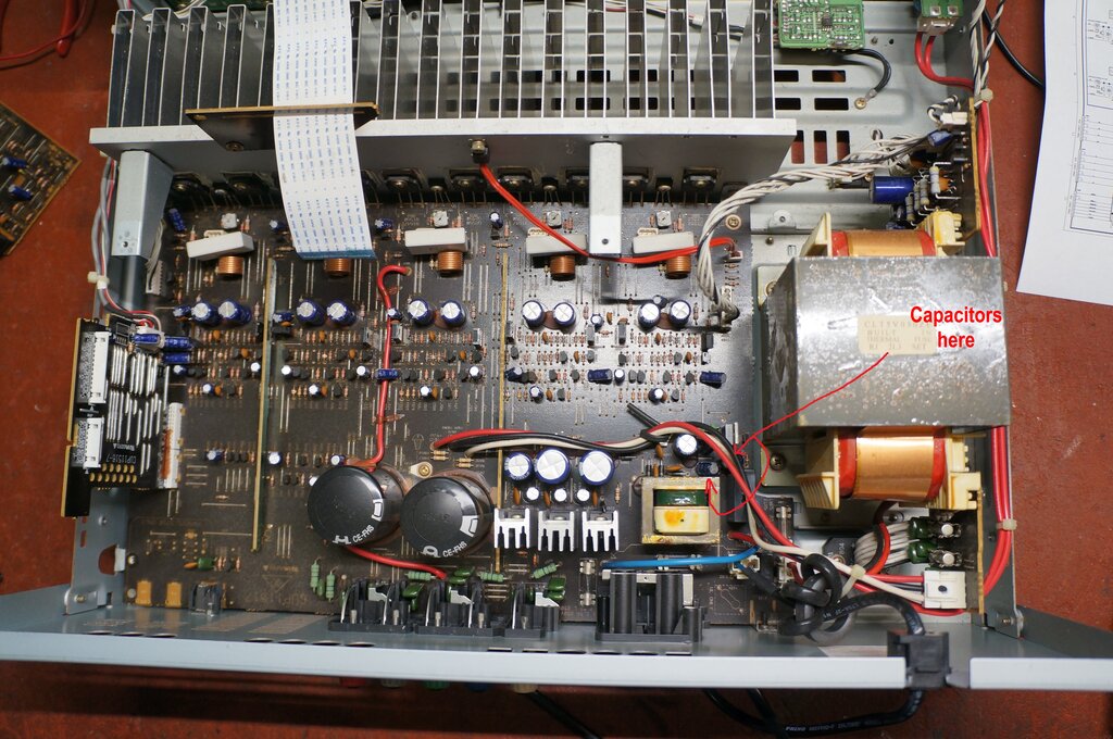
Location of the two faulty capacitors. Note the small on board transformer.
The relay is just to the right under the wires.
I bridged across the relay contacts with
a 100W light bulb, and the display lit up. So, it was obvious the relay
wasn't doing anything. The relay is switched by transistor Q901. The base
voltage varied from 700mV with the power switch on, to 0V with it off.
At least it wasn't a microprocessor problem! That leaves the transistor,
relay, and power supply for the relay. Short circuiting collector to emitter
of the transistor did nothing. The supply seemed a little questionable
dropping to around 9V when the switch was on. The relay is a 12V type.
Relays switching transformer primaries
don't always have a long life because of the inductive load, so this was
suspected. In any case, the lower PCB would have to come out.
Despite three levels of PCB's, the unit
is actually not very difficult to dismantle. Remove all the self tappers
holding the sockets to the back panel. Remove the two top PCB's. Remove
the three heatsink screws at the front. Don't remove the self tappers at
either end of the bottom board, which secure the heatsink to the PCB, or
the output transistor leads and the tracks to which they connect will be
stressed and may be damaged.
Be careful of the ribbon cables. Some
of the cable ties need to be released. I'm a tight arse and undo them rather
than cut them, so they can be reused.
With the lower board out, I desoldered
the relay. It tested perfectly. Whilst in the area, I checked the nearby
electrolytic capacitors, and here I found the 470uF (C911) and 220uF (C912)
had a rather high ESR, up around 7 to 12 ohms. Replacing them fixed the
fault.
AWA P4 "Telstar" 17" Portable TV and 6CM5 Valves.
Working happily with a Philips 6CM5.
"The Serviceman" in Electronics Australia, November 1978 described an unusual fault where an AWA P4 television would only work properly with AWV 6CM5 valves, but not Philips / Mullard. Apparently, when a Philips valve was installed there was a break up of the picture when the brightness of the picture was reduced. The description inferred some kind of spurious oscillation, which could be heard from the line output transformer. A fellow HRSA member reminded me of this article, and since I have a P4, I decided to see for myself.
A selection of Philips 6CM5's were tested.
As it turned out, for my set at least, a range of Philips and Mullard 6CM5's were tried with complete success. The picture was completely normal and stable throughout the full range of the brightness and contrast controls.
6CM5 socket at left. 6AU4 at right. The only tie point is pin 6.
It is true that there are physical differences
between the internal structure of the AWV and Philips valves, and there
are also extra internal connections with the Philips valves. Initial thoughts
were that maybe the extra internal connections were connected to pins which
were being used as tie points on the valve socket. However, this is certainly
not the situation with my P4. And in any case, the Philips 6CM5's were
reputed to work normally with the picture at full brightness, which precludes
something as drastic as active pins being connected to the wrong places.
The only tie point is pin 6, used for the grid stopper resistor. It's conceivable
that if a particular 6CM5 had an internal connection between pins 5 and
6, that instability might result with the grid stopper shorted out, but
all the 6CM5's tested did not even have pin 6 present on the valve base.
It will have to remain a mystery until
someone with a P4 displaying this 'fault' comes forward.
Incidentally, the cabinet design of the
P4 is not service friendly. It takes some careful juggling to get the back
on. Operating the set without the back requires two legs to be folded down
at each end of the chassis. I was told by an AWA employee that the design
department came up with the cabinet, and that the people designing the
chassis and electronics had to come up with something that fitted it. This
is why it's an awkward set to work on.
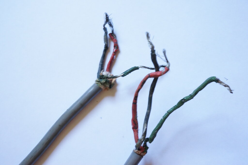
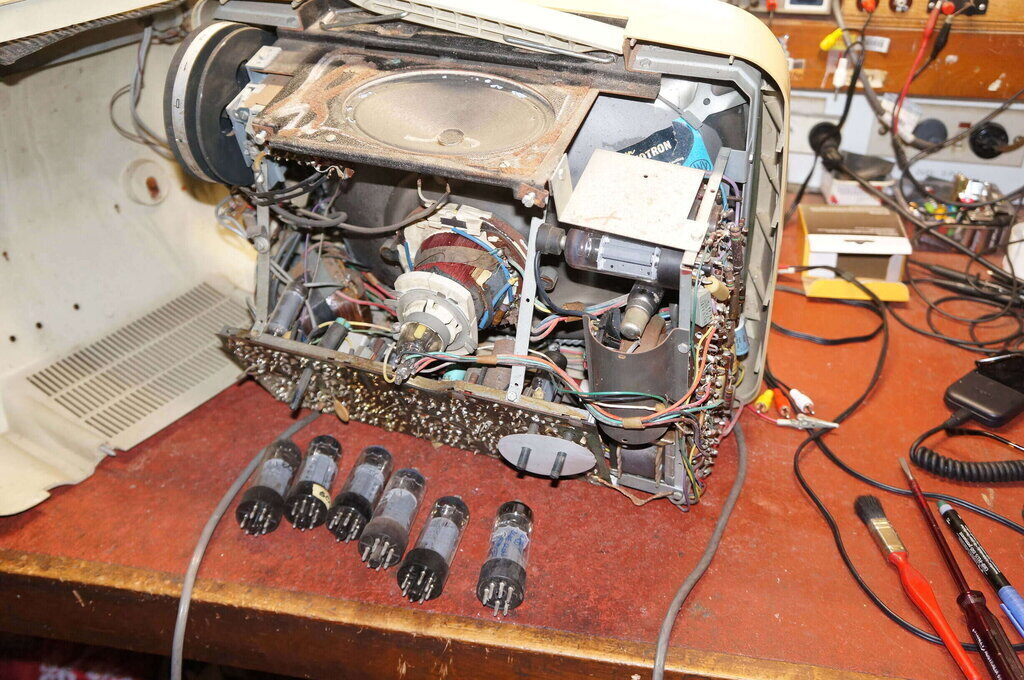
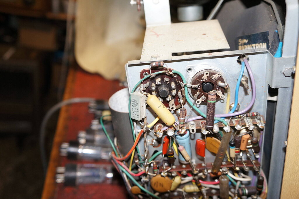
From an extension lead which tripped the circuit breaker. Although
this 1960's era cable has PVC outer insulation, the inner conductors are
rubber insulated.
Rubber insulated wire has come to the end of its life. Until now (2025), I had happily kept using original rubber insulated wire in use. Of late, it has suddenly deteriorated to the point of being unsafe. If it hasn't gone brittle, it has gone soft, to the point of the conductors coming through the insulation as shown above. The deterioration is much more evident where the conductor is exposed to air. On that basis, one can strip back the outer insulation and the insulation appears quite OK. But, before long, it will revert to the previous condition. I am now removing this kind of cable from use as I encounter it. As much as originality is nice, it's not worth the fire risk.
Plasticiser leaching from power cables.
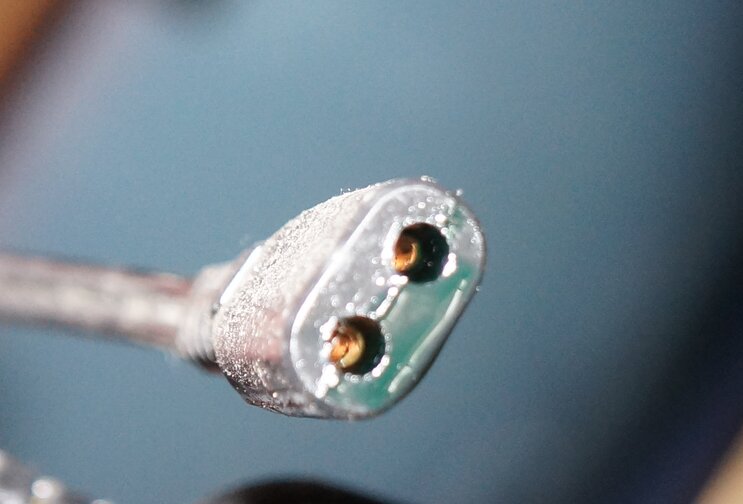
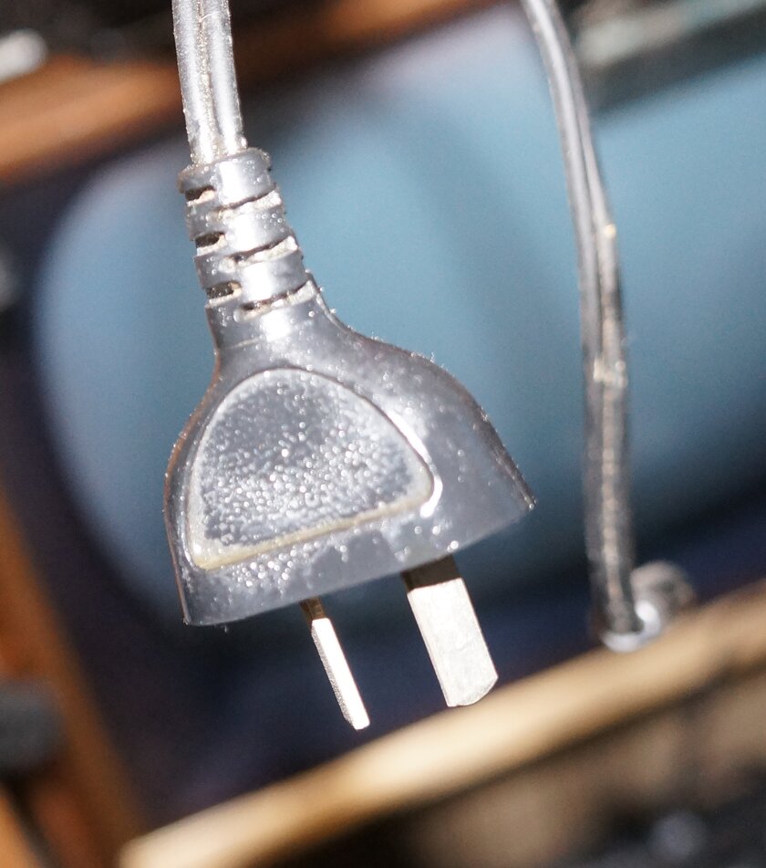
Several cassette type power leads, of Kawasaki brand have been observed to have the appearance of a liquid substance on the surface of the plugs. These are of 1980's era. In the extreme case shown on the left, the cable had been hanging for several years and the liquid was almost ready to drip from the plug. The same effect has been noted with telephone handset cords of Japanese origin (e.g. Red Phone and Gold Phone). The cords become sticky and collect dirt. Presumably, once sufficient plasticiser has leached out, the cords and connectors will start to become brittle.
On a similar note, when storing plastic radios etc, with a plastic mains cable, do not coil the mains cable up so it is resting on the cabinet, or wrapped around it. It will dissolve the plastic.
No service manual available, and there's an intermittent fault.
Where would you start?
There is no service manual available unless
you're an authorised agent (I always avoid such products), but the user
manual points out that the output is at normal cartridge level, or line
level. As well, there is a digital output.
The service access isn't great. Upon removing
the bottom of the machine, all these little spacers fell out, and into
the guts of the machine as well. They slip over the screws. Their purpose
is not clear, but it does seem as though the bottom and top halves of the
case might be a mix and match arrangement from different models. I say
this because there are preset pot access holes in the bottom which don't
line up with anything actually inside.
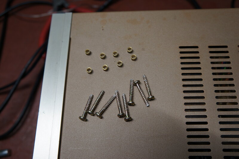
Watch out for the little spacers. They fall off into the machine
when the bottom is removed.
The screws are a pain to put back in too,
because the whole thing has to be held vertically so the spacers don't
slip off before you get the screws in.
Anyway, back to the fault. One of the
bad designs about this turntable is the short straight arm. Apparently,
it's meant for DJ use (it does have reverse direction among the features).
The problem is the awful tracking which results as the arm moves across
the record. The angle is so off, that I was worried about ruining my 'good'
records. So, I used some worn 45's for testing. The owner is going to only
use it for 78's, which should be OK, since those can be played with something
as crude as a sewing needle, without harm.
Fortunately, the fault did reveal itself
part way through a Ted Mulry record. The audio faded out on both channels
and came back. It was like a 'soft' switching, rather than an actual connection
failure.
Now, you would think that for the "phono"
output, the cartridge would connect directly to the output leads, which
would make that fault seem almost impossible. But not here - in fact, disconnecting
the mains did cause the audio to fade out. So, obviously, the cartridge
signal was going through active circuitry, despite the output being at
cartridge level. In fact, the cartridge wires terminate on the inputs of
a 4066 IC, which is a four channel CMOS switch. I had noted that the 4066
was also associated with the Line Input socket, and it looked as though
the 4066 was switched using the contacts in the socket. That seemed a likely
fault possibility, since the turntable looked as though the dust cover
had been lost years ago, and the socket opening was pointed upwards. Entry
of dust into the contacts is just the kind of thing which could cause this
problem. I gave it a squirt with CRC, and it seemed OK, so was about to
declare it fixed, but once again the fault appeared.
Getting access to the component side of the PCB is a pain. Not only is it tethered around three sides with cable ties and various plugs and sockets, making it impossible to flip up, but it turned out that the speed control pot, which is soldered to the PCB, is secured to the top half of the case. The screws are under an adhesive plastic escutcheon. Chances are, that would get disfigured if I tried removing it, so I had to desolder the slider pot and lift the PCB off that. Thoughts came to my mind of simply connecting the cartridge wires straight to the output, but that wouldn't actually be finding the fault. Like it or not, the cartridge signal is amplified, and then attenuated when "phono" level is selected. Not a very hi-fi arrangement, but I think this machine is more about show than quality. The plastic chassis is actually quite flimsy once the bottom is off. A thick steel plate secured to the bottom half of the case gives the machine all its weight.
It started to make sense now, why both
channels failed under fault conditions. The 4066 switching level could
be wrong, or some supply fault to the subsequent amplifier stage. I noted
a 5V supply feeding the 4066. One of the difficult things about servicing
turntables is not being able to run them upside down. I just used a screwdriver
to inject hum into the cartridge terminals, to substitute for a playing
record.
Not sure why, but on impulse, I actuated
the turntable lamp. I think this is for being able to see where to lower
the cartridge in a dark studio. The audio dropped out every time I turned
on the lamp. Yet, the lamp looked like it was operating normally. Tracing
back the source of lamp voltage, it came from a 12V rail created by a 7812
regulator. However, I had noted the no load lamp voltage was about 11.4V,
and with the lamp on, it was 10.4V. The active circuity, between the 4066
and output, evidently didn't like this amount of voltage drop. It was clearly
a case of the regulator dropping out under load. Sure enough, a CRO on
the 12V rail showed ripple, which increased markedly when the lamp was
on. Aside from a faulty regulator, the only thing that would cause that
is insufficient input voltage. The 78 series regulators need a few volts
of headroom. Here, the input was about 14.5V with the lamp off, and about
13.2V with it on. Next point of call was the filter capacitor. This was
on the main board along with its rectifier. It's fed from the yellow transformer
wires, which produced about 16V.
Touching another 1000uF across the filter
didn't do much, which left the rectifier. I had noted the ripple waveform
looked half wave. Touching a 1N4007 across each of the diodes in turn established
one was open circuit, since full voltage was restored, and the audio worked
with the lamp on. The rest was easy. Once the speed control pot was desoldered
again and the board lifted up, the diode was replaced.
It was also found that the volume control
was ineffective. On one channel, the sound was full volume and on the other
there was no volume. The volume control is a 6 pin vertical PCB mount type.
It was open circuit. Yet again, we have a fragile volume control in a situation
it should never have been used in. To remove the volume control entails
taking the radio board out, and then cutting away some plastic adjacent
to the potentiometer pins. This is required to get a soldering iron in
there. Alternatively, the whole plastic dial part would have to removed,
which would involve restringing the dial - and it's not simple. The pot
is an obscure type, not readily available. I substituted it with a conventional
dual 50k miniature type with long fluted shaft. This required drilling
the PCB to mount the new pot. An insulating washer was made up to prevent
PCB tracks being shorted when the pot was mounted. Wires were run from
the PCB to the new pot.
Note that the power switch is a plastic
tab on the shaft which actuates a micro switch. Its positioning is thus
important.
The CD player was unresponsive, but cleaning
the lens fixed that. Performance is very mediocre on FM with poor sensitivity.
It is certainly not a DX receiver! It is not stereo. MW is very good, however.
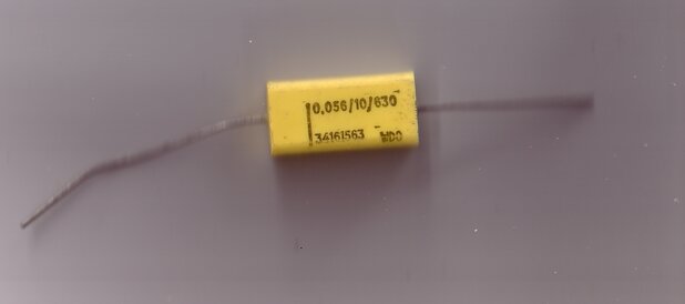
For the second time, I have found the above
type of capacitor open circuit. These were new old stock. The first time
I encountered this was with this Vane
453 tester.
Recently, when working on a 12V VHF receiver,
while trying to improve the audio quality, the sound suddenly lost all
the bass response. One of these .056uF capacitors was used as the grid
coupler to the 12AQ5 output valve. It measured in the pf region.
Replacing it with a conventional greencap
type not only fixed it, but got rid of the "it just never sounds right"
problem which had existed since building this radio. The particular capacitor
when tested a few days later, tested normal. I've removed all these capacitors
from my stock!
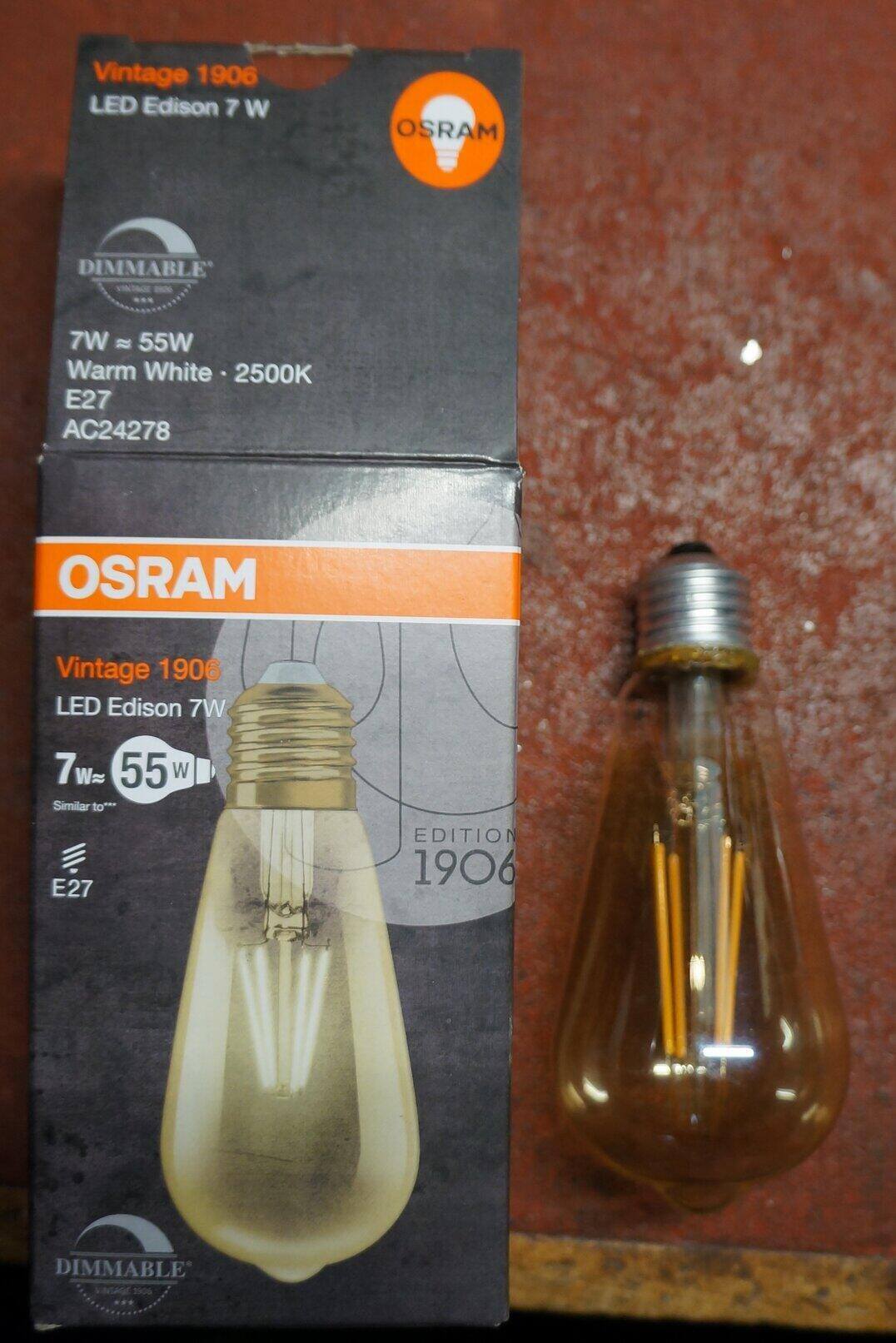
This vintage style LED bulb was damaged in a storm. Typical solid state electronics dies soon as there's a spike on the mains. At $18, it was worth repairing. Internally, there was a PCB inside the base with a rectifier, filter capacitor, and a linear regulator. The fuse, rectifier, and MOV had all been damaged. Bypassing these with an external DC source did not restore operation, indicating the regulator and/or ancillary components were also damaged. Since these are obscure surface mount components, it was decided to bypass the whole lot with either a resistive or capacitive ballast.
The actual LED required about 266V, and with a power rating of 6.5W, would indicate a maximum of 24mA. While the box says 7W, the Osram data sheet says 6.5W. There was obviously no room inside the base for any normal capacitor to act as a ballast, so the tried and trusted resistor method was used instead.
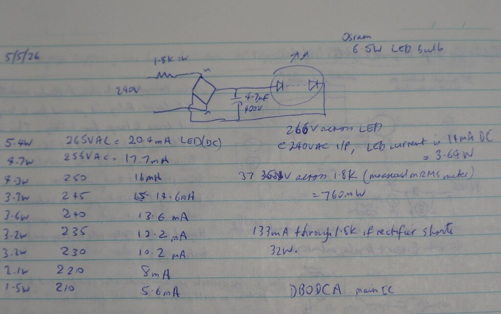
It was felt better to have the resistor first, then the rectifier and filter capacitor right at the LED. This way, the resistor absorbs any spikes on the mains, and can act as the fuse. Given the limited space for the resistor, and taking heat dissipation into account, I settled on 1.8k 1W for the resistor. See the currents for a range of mains voltages in the table above. The brightness is ample at 3.4W, and not noticeably dimmer than the official 6.5W. Furthermore, LED life will be much longer - remember, many LED bulbs overdrive the LEDs - they can't have them last too long or profits are less.
The stem supporting the LED filaments had
cracked around the base of the glass, and eventually fractured. I used
Araldite to secure it back in position. It's a puzzle why this happened
- perhaps the physical shock of the components on the PCB blowing up? Fortunately,
the LED filaments don't need to be in a vacuum or gas filled atmosphere.
However, I would assume something like nitrogen had been used to keep moisture
out. Some cheap bulbs I have open to the atmosphere do fog up. I used a
piece of Veroboard cut to the same size as the original PCB to mount the
components. The rectifier needed to be SMD to fit, and I got one from a
dead Apple charger. The 4.7uF filter capacitor was taken from the original
PCB. It was found a single 1.8k 1W resistor was too big to fit comfortably,
so 1k and 820 ohm half watt resistors were used. Hot melt glue was used
to put the whole thing back together - not too difficult to open up again
if necessary. The original E27 base was destroyed dismantling it, so one
was obtained from an o/c incandescent bulb.
The resistors should be flameproof in
case the rectifier shorts. In this case 32W will be dissipated!
Presumably, the linear regulator IC operated as a constant current source. In which case, the current would be more stable over a wider range of mains voltages. The regulation of a resistive ballast improves as more of the total voltage is dropped across the resistor, rather than the load. It starts to then behave as a constant current source, when the load voltage is a small fraction of the supply voltage. In this instance, the load voltage is high (266V) relative to the rectified mains (340V), so there's less current regulation. As a compromise, the ballast is calculated using the maximum likely mains voltage, so that the current is never exceeded. At the normal mains voltage, the load will therefore be under run slightly. I used current and power meters to determine the value of the resistor. Obviously, a resistor higher than that calculated should be used to begin with.
End result was a power draw of 3.4W, current of 16mA, and power factor of 0.82. This was with the supply at 235V and measured on a HOPI power meter.