Radar TV Replacements was a manufacturer
of transformers, power supplies, and inverters. Some of their inverters
have been described elsewhere on this site.
This inverter came to me from a very kind
reader who had used it to power a telescope of U.S. manufacture. As it
happens, the 12ST40 has a variable frequency output, from 40 to 60c/s,
which takes care of the motor speed (dependent on the supply being 60c/s),
and a Ferguson step down transformer was used to provide 115V. The complaint
was that, apart from being a cumbersome set up, with battery, inverter,
and transformer, the inverter ran very hot. Also, 240V was usually available
from the mains where the telescope was used which made the battery unnecessary.
What was really needed was a something to convert 240V 50c/s to 120V 60c/s.
Such things do exist in the modern day, but as a lower cost option, I suggested
that a 12V power supply be used to power a modern sine wave 12-120V inverter.
This would eliminate the battery and transformer, and the motor would appreciate
the sine wave. Square wave inverters are not ideal for operating inductive
loads, such as synchronous motors, since the output is full of harmonics.
At the time when these Radar inverters were being produced, most designs
produced a square wave, since this was the most efficient way to use the
available technology. In the modern day, with switchmode techniques well
established, pure sine wave inverters are readily available and inexpensive.
And with the convenience of internet purchasing, it is a simple matter
to obtain one with a 120V 60c/s output, for operating U.S. appliances in
Australia.
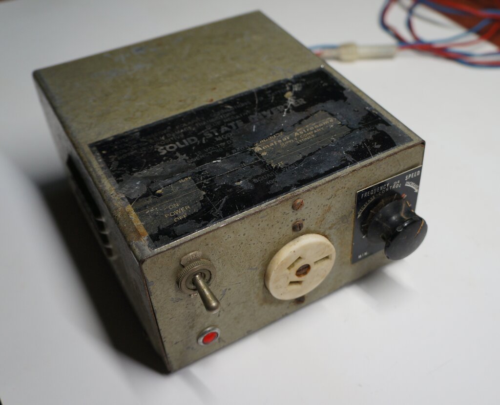
The 12ST40 had been well used. Most of the decal on the cabinet top had been worn away, but I was able to make out the model number. Additional labels had been applied, stating that it had been sold by the "Amateur Astronomer Supply Company" in Sydney. I noticed that the 12V supply leads had been extended. They were terminated in battery clips. There is an inline fuse holder which contained a blown fuse. This had been bridged out with a piece of fuse wire; probably 8 or 10A judging by the gauge. Evidently, the inverter had been unhappy about something at some time.
Introduction to the 12ST40.
The first inverters produced by Radar
were 40W types in the late 1960's. An interesting feature was their variable
frequency control, which was intended to allow fine speed adjustment for
turntables or tape recorders that might be used with the inverter.
A phase shift oscillator produces a sine
wave of 40-60c/s, which is then squared up and fed to the output transistors
via a driver transformer. The output transistors then switch the step up
transformer in the usual way, producing the 240V output.
This uses the same PCB as the first generation of 100W inverters.
My experience with Radar inverters is that they're conservatively designed and very reliable, so it was no surprise that it worked straight away. With a 40W light bulb as a load, some flicker was evident. The original supply leads were running warm. Looking at the output waveform, there was noticeable rounding off of the square wave on one half of the cycle, and one output transistor ran slightly hotter than the other.
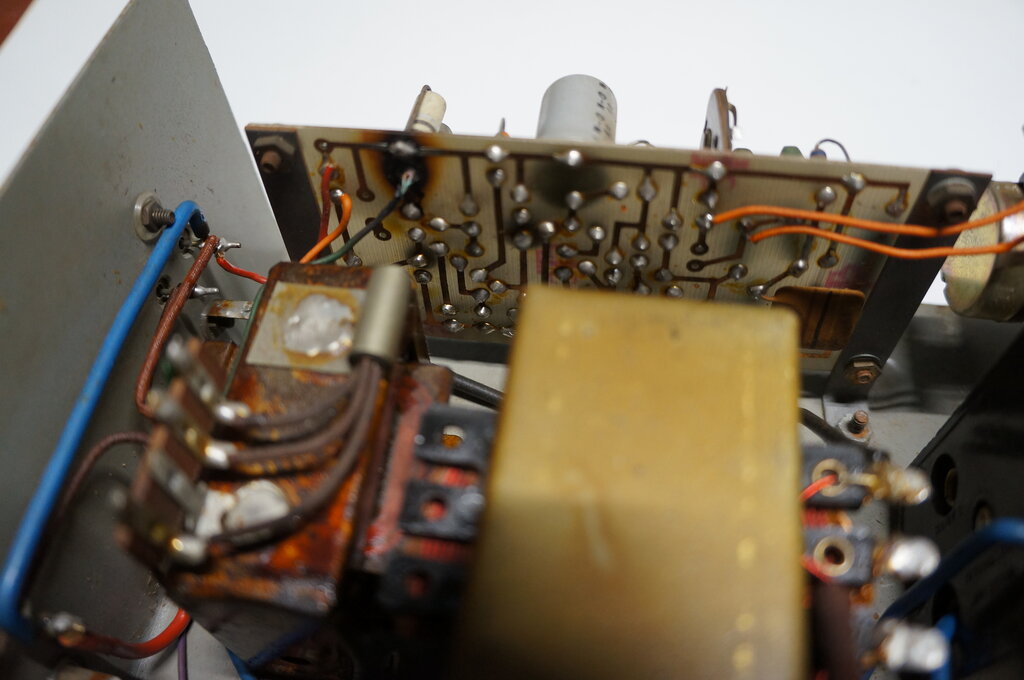
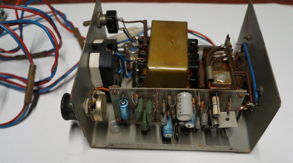
The burned PCB can be seen at the top left.
As soon as I looked inside, it was obvious
that the 100W design
had been developed from this. The PCB with oscillator and driver circuit
is identical, and as it turned out, the circuit is virtually identical.
Similarly, the output transistors are
driven directly from a driver transformer. Perhaps the most curious thing
was a very overheated 10R resistor, and a burnt PCB around it.
The output transistors are types AT301.
As far as I'm aware, they are Anodeon's version of the 2N301. This is a
PNP germanium transistor in a TO-3 package.
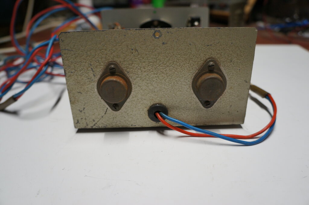
AT301 output transistors. Case functions as the heatsink.
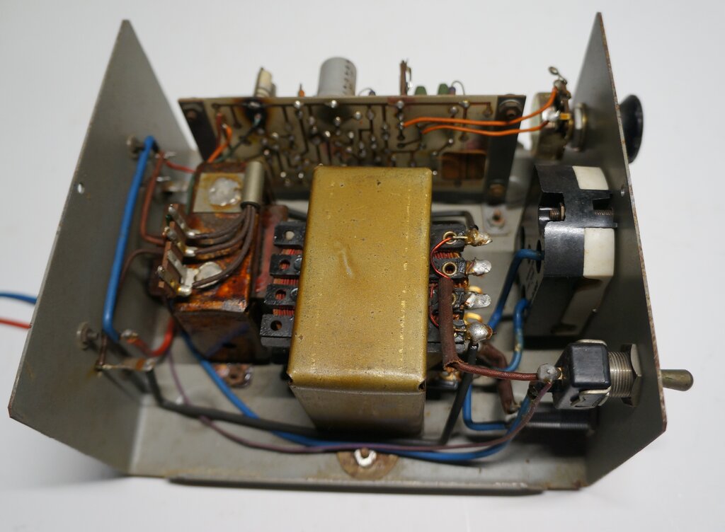
Driver transformer at left with driver transistor mounted on it.
Output transformer in middle. The two middle connections at the top of
the transformer are a mystery, since they have windings connected, but
are not continuous to anything.
The Circuit.
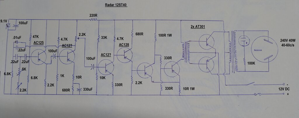
Being of 1960's design, all the transistors
are PNP germanium types. As such, note that the 'earthy' side of the supply
is in fact positive. This is not a problem in terms of using the inverter
in a car, because the case is not connected to anything.
The inverter's timebase is a phase shift
oscillator based around an AC125 and another indeterminate AC type (the
transistor cases have oxidised sufficiently to obliterate some of the printing).
A phase shift oscillator works by virtue
of a capacitor-resistor network. Each time a signal is passed through one
such network, the phase shifts by 90 degrees. Therefore, if we have an
amplifier whose input is fed from its output via three resistor capacitor
stages, then the phase shift will be more than 180 degrees, and the amplifier
oscillates.
As can be seen, each stage is identical,
with the exception of the intermediate stage, where the 6.8K resistor is
replaced with a preset 2.2K and the panel mounted 5K pot. The 2.2K preset
sets the limit of the 5K pot so that the user adjustable frequency range
is 40 to 60c/s. In the case of the 100W inverter, the 5K pot is replaced
with a fixed resistor, since the frequency is not user adjustable.
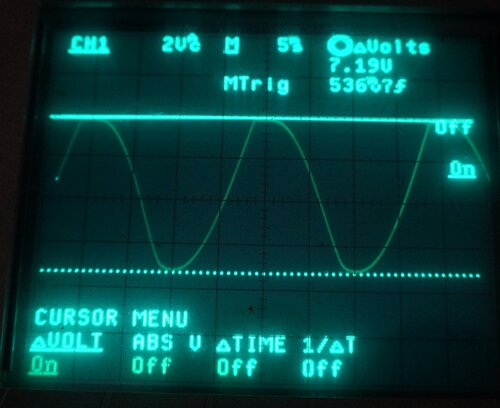
Phase shift oscillator output at collector of second transistor.
The output is a sine wave, albeit with
some distortion, and is available at the collector of the second transistor
via a 2.2K preset. The supply voltage for the phase shift oscillator is
stabilised at 9.1V with a zener diode.
The sine wave then passes through a 100uF
capacitor into the next two stages of amplification, using another unidentified
transistor and an AC128.
Form the emitter of the AC128, the signal
passes into two more transistors. Both these have heatsinks, so the type
number was obscured, but are likely to be AC128's. The transistor which
drives the driver transformer primary is mounted on the transformer case
for heatsinking.
Note that this transistor, and the one
preceding it, have a common emitter resistor - this being the overheated
10R referred to previously. This connection causes a degree of positive
feedback between the two stages. It is in fact a Schmitt trigger circuit.
Current flowing in the driver transistor will cause a voltage drop across
the 10R. Since the emitter of the preceding transistor also sees this increase
in voltage, its collector current drops, increasing the base current to
the driver transistor, via the 100R and 330R resistors. This in turn increases
the driver transistor current even more until it saturates.
In effect, it operates as a very fast
acting switch, operating in only one of two states. Thus, the sine wave
is converted to a square wave, and for this reason the distortion present
in the sine wave is not important.
Because the input of the Schmitt trigger is voltage sensitive, the level of the sine wave will affect the duty cycle of the square wave output. In this regard, the 2.2K preset at the phase shift oscillator output operates as a duty cycle control. For maximum efficiency, this is set to 50% so that both output transistors conduct for an equal period.
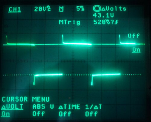
Waveform across full primary of the output transformer.
The AT301 bases are fed directly from the
secondary of the driver transformer, which drives each transistor alternately.
Being a class D output stage, there is no initial bias. The output transistors
are either fully on or fully off.
From here, the output transformer steps
up the collector voltage to 240V. A neon indicator shows that there is
output.
Like all the other Radar inverters, the
secondary of the transformer feeds the live and neutral pins of the output
socket with no earth connection. The earth pin does not connect to the
case or anything else.
A rather puzzling thing was to do with
the output transformer. There are two unused tags for the primary winding,
which have wires terminated to them, but there is no connection between
them or anything else.
Looking closer showed that the one end
of each was unconnected and taped down over the bobbin insulation. So,
we had two extra windings, but what for? Seeing as they appear to have
only a few turns, and were of much lighter gauge, it occurred to me that
this transformer may have been used in a self oscillating inverter circuit,
whereby these other windings were used to drive the output transistor bases.
I am not aware of any Radar inverters (yet!) which are self oscillating,
so it remains a mystery for now.
Getting it Going.
First thing to deal with was the rounded
off waveform for one of the AT301's. This was easily dealt with by readjusting
the duty cycle control. As expected, the input current dropped slightly,
and the transformer buzz was less, since there was now no core magnetisation.
Also, the flicker in the lamp was no longer visible.
Output frequency measured 42 to 62c/s.
The overheated 10R was replaced. It was
found that its resistance had dropped to about 7R. While this resistor
runs warm, it certainly shouldn't be enough to char the PCB. It is not
clear why this happened; and can only guess the inverter had been used
under unsuitable operating conditions in the past.
The warm power leads were of concern. It
turned out that there was 1V drop across them when the output was fully
loaded! That was clearly unacceptable, and looking at how thin the conductors
were, it was perhaps not surprising. I would not run more than about 2A
through wire of that gauge, but they were clearly original to the inverter.
Conveniently, the wires which had been used to extend them were about twice
the thickness.
I simply removed the original leads and
used those which had been added (they had the same colours). Despite the
longer length, the voltage drop was now down to 400mV at full load. The
fuse holder was transferred across, and a 5A fuse installed.
While it seems to be commonly done, it
is not recommended to extend the leads of the 12V supply because of the
resulting voltage drop. It needs to be remembered that in the case of a
12 to 240V inverter, the voltage step up ratio is 20 times. If there is
a voltage drop of, say 1V, between the battery and inverter, then the output
will be 220V instead of 240V. If the appliance needs to be located at a
greater distance from the battery, the best way to do this is to locate
the inverter at the battery, and extend the 240V wiring. The current in
the 240V wiring will be 1/20 of that in the 12V wiring, and the voltage
drop will be insignificant.
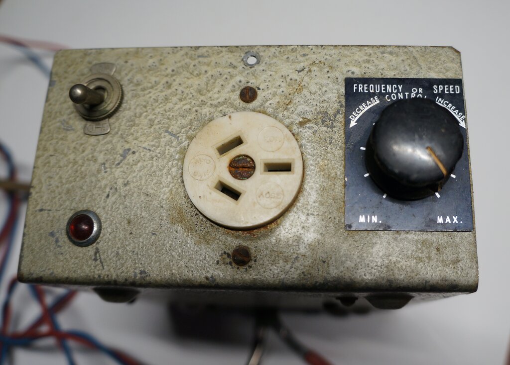
Front panel shows switch, neon, socket, and frequency control.
Performance.
Input was maintained at 12.6V at the lead
ends, and the following results obtained. Loads were incandescent lamps.
| Load | Output Voltage | Input Current |
| No load | 302 | 700mA |
| 15W | 272 | 2.1A |
| 25W | 255 | 3A |
| 40W | 233 | 4A |
Regulation is very typical for this kind
of inverter. Efficiency at full load is 83%, which is as expected. As can
be seen, with low loading the voltage could be damaging for some applications.
In fact, I wonder how the telescope motors survived, since they may have
been fed with up to 150V - assuming the stepdown transformer was not saturating
with an extra 50 odd primary volts.
It is unfortunate that no output level
control is provided, as with the larger inverters, but it really is necessary
if loads of less than about 25W are to be used.
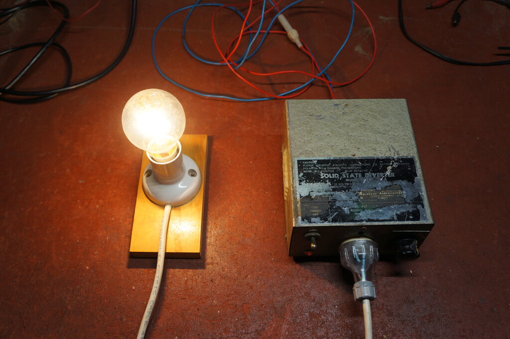
Inverter operating 40W light bulb.
Provided its limitations are kept in mind,
it is nevertheless a well designed and useful inverter. The subject of
square vs. sine wave output has been discussed in various other inverter
articles on this site. Briefly, a square wave inverter will produce a peak
voltage of 240V. Here, the peak voltage is the same as rms voltage. For
a sine wave, the peak is 340V for 240Vrms. Where the peak and the rms values
are the same, incandescent lamps and heating elements work normally, since
these loads are dependent only on the rms (which is the heating power).
The problem can be with electronic loads because the filter capacitors
charge up to the peak voltage, and not the rms.
In the case of loads where the AC is rectified
for a DC supply, the voltage will be lower when the supply is a square
wave. Take for example, a transistor radio which works off 240V AC, but
internally runs off 9V DC via a transformer and rectifier. When run off
a square wave inverter, the peak input voltage is 240 instead of 340, and
the radio will now be operating at about 6.3V DC.
An ironic situation exists with a poorly
regulated inverter, however. If we take this Radar for example - operating
this transistor radio (which is almost no load), the AC supply is around
300V, and so the radio will actually be operating at closer to 8V. That
is, provided its power transformer does not object to this higher voltage
being a square wave.
While square wave inverters are very efficient,
they must not be thought of a direct substitute for the mains supply, and
that anything will run off them within the specified power rating.
Some might wonder why, since the phase
shift oscillator used in the Radar produces a sine wave, that the output
isn't also a sine wave. Well, it could be, and inverters have been
made that way, but it comes down to efficiency.
To make the output stage produce a sine
wave, the transistors would have to work in class B, and over the linear
part of their curve. The power dissipation would rise markedly, since the
transistors would effectively work as variable resistors. This power dissipation
requires more heatsinking, especially with germanium transistors, and of
course this heating power is reflected by an increase in supply current.
Modern sine wave inverters use switchmode
techniques, where the output devices are still used as switches for efficiency,
but their drive is such that the duty cycle varies instead. Provided the
duty cycle varies at the correct rate over each cycle, the output will
be, once averaged by a low pass filter, a sine wave.
As it is, the output transistors on the
Radar barely run warm even at full load.