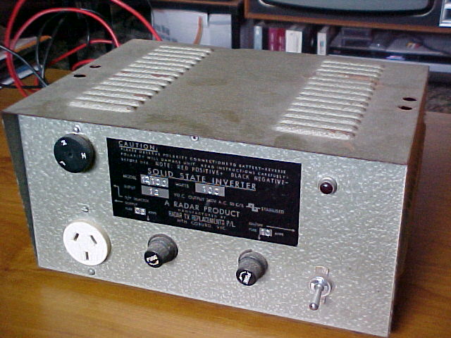
Radar 12/100 Inverter - early model.
This inverter came into my possession back
in 1981. It had previously been used in a car to run a P.A. amplifier -
hence the holes drilled into the lid to secure it under the dash.
Along with this inverter, I was also given
a 250W version which was unfortunately faulty. Back then I was incapable
of fixing it, so it got dismantled. I kept the transformer which did get
used in a much later EA circuit.
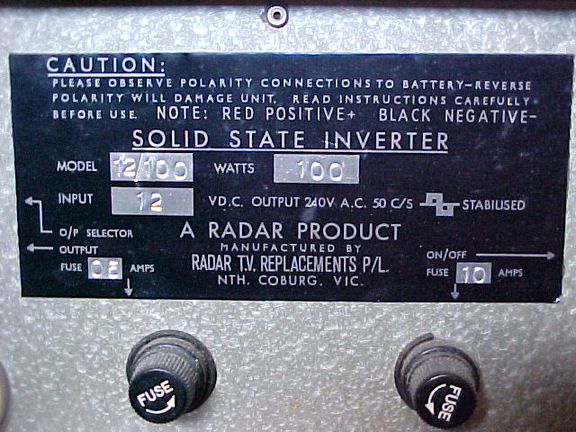
Radar TV Replacements of North Coburg,
Victoria, manufactured a range of solid state inverters in the late 1960's.
Given the rarity of early Australian inverters, I have never seen any other
100W or 250W models, but there is a smaller 40W model which has appeared
at swap meets.
The Radio Parts catalog of 1968/69 lists
several models, but no high power ones for 12V. Only 24 and 32V models
are listed for 100W, 180W, and 250W.
It would appear the 100W-250W 12V models
came later. If the date stamps are any indication, the 100W inverter that
I have, model 12/100, was made in 1972.
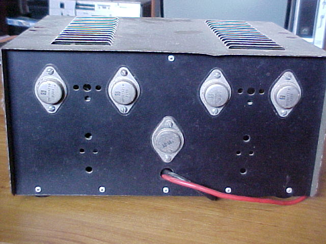
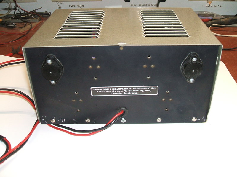
On the back panel are mounted the four 2N3055 switching transistors,
and beneath them is the AD149 driver transistor. In the 250W model, the
holes between the 2N3055's are occupied by single high power germanium
transistors.
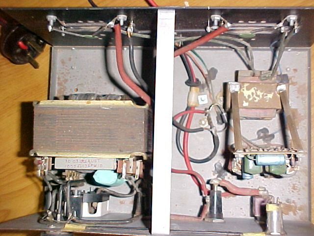
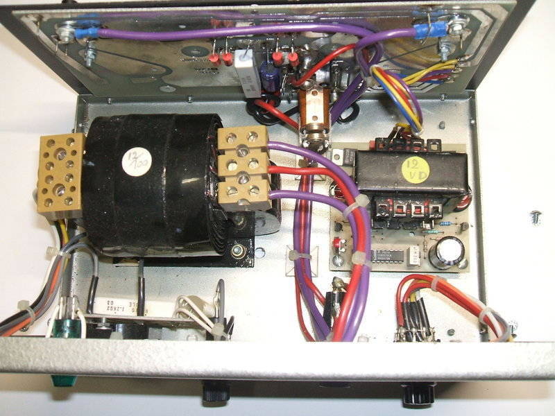
Internally, the unit has a lot of vacant space but this makes everything
easy to get at.
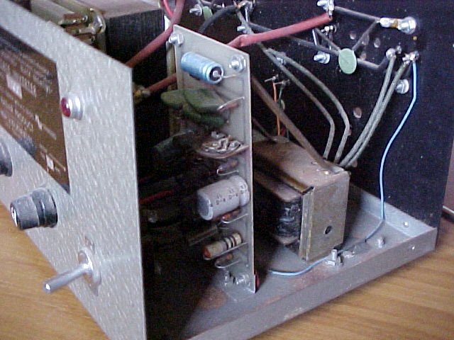
The oscillator/driver PCB is visible here. Behind it is the driver
transformer.
The Circuit.
.jpg)
With the exception of the 2N3055 output
transistors, all other transistors are germanium types.
It was not possible to identify those
on the oscillator/driver board without removing them, but it's safe to
say they're all PNP and of types such as AC126 and AC128.
A phase shift oscillator, using the first
two transistors on the left, generates the 50c/s waveform. The supply
to the oscillator is regulated with a 9.1V zener diode so that the frequency
remains constant over a normal variation in supply voltage. The oscillator's
output is then AC coupled to a three stage amplifier which drives the AD149.
Interestingly, the PCB which contains the oscillator and driver circuit
is made by STC.
The AD149 drives the 2N3055 output transistors
via a transformer to create the anti phase waveform required, as well as
to provide sufficient base current. It is interesting to note that the
2N3055's are simply paralleled in pairs without any emitter or base resistors.
This would suggest they should be matched pairs.
The output transformer steps up the 12V 50c/s to 240V in the usual way. The secondary is tapped with a selector switch to provide High, Medium, or Low settings. A neon shows the inverter is functioning. An RC circuit consisting of a 1K 10W resistor and 0.47uF capacitor provides shaping for the output waveform. Fusing at 500mA is provided for the secondary circuit, while a 10A fuse protects the 12V input. The 240V output is fully floating and the earth pin of the socket is not connected to anything. In preparing this article, I found that the inverter had been running without the output RC circuit working. One of the leads for the 0.47uF was broken underneath the spaghetti tubing. It was only when doing measurements looking at the current through the 1K resistor that there was suspiciously no current flowing. Apart from that I had always noted the 1K resistor never ran warm. Now it does!
As originally manufactured, there is no
reverse polarity protection. It is true that the 9.1V zener would protect
the oscillator, but the rest of the inverter remains unprotected.
I thought this was unsatisfactory, so
connected a 1N5404 diode across the 12V supply after the 10A fuse. If the
the supply is reversed, the diode will conduct and blow the fuse.
Performance of this inverter is very good
and copes with low power factor loads well. It will happily run a 40W fluorescent
lamp with no power factor correction, even though this is not very efficient.
No load current draw from 12V is 1.2A. A 15W incandescent lamp results
in a 2A current draw at 12V, and a 40W lamp draws 4A.
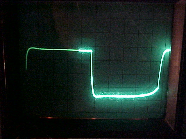
240V output waveform into a resistive load.
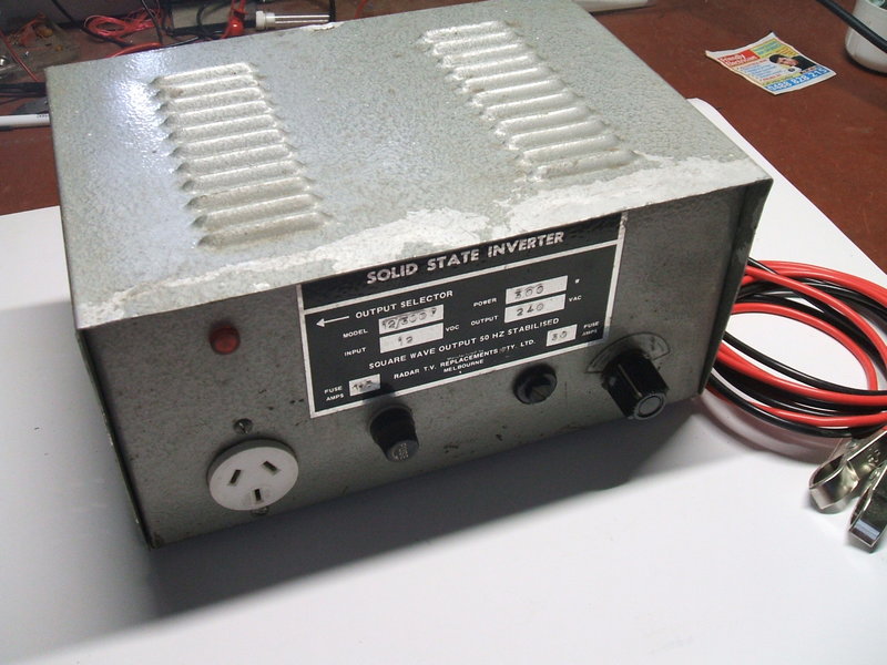
Radar 12/100 Inverter - late model.
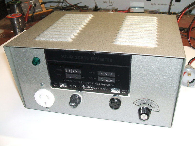
This was recently acquired at an HRSA meeting. Of course I recognised it, and had to have it. Obviously, it is an updated version of the inverter just discussed. From the date stamps on the components, it is of mid 1980's manufacture.
By this time, Radar TV Replacements was now under the name of Invertech Equipment Company P/L. Despite my interest in inverters, I had never heard of this company, and I was surprised that a clone of the old Radar inverter was still being manufactured 15 years after the original.
The newer version is very elegantly constructed.
It is lighter, with the case now of aluminium, and the more efficient C
core transformer lessens the weight also. It is particularly good to see
reverse polarity protection fitted. This could have easily been fitted
to the original model.
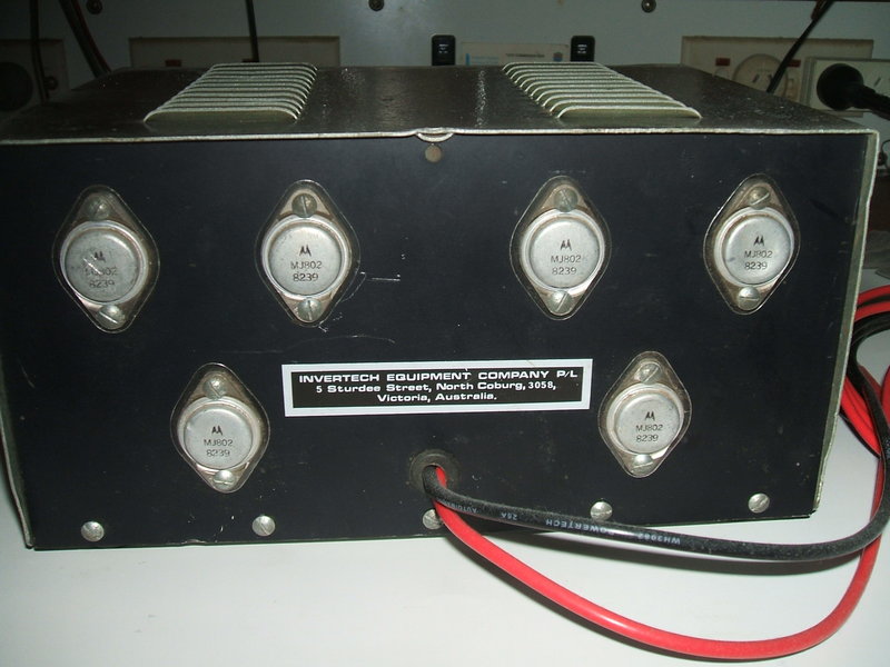
Not surprisingly, all semiconductors are
now silicon, and there's even a CMOS IC to take place of the older germanium
transistor based oscillator. Interestingly, the output transistors are
still being driven by a transformer.
The inverter remains unregulated, but
instead of the valve socket based selector switch used previously, this
version has a rotary switch which also provides the on/off switching.
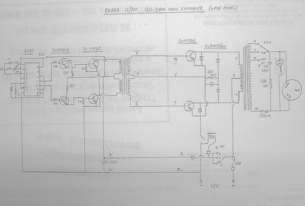
The timebase uses a 4047 operating as an
oscillator. The convenient thing about this IC is that it provides both
inverted and non-inverted outputs, and with a 50% duty cycle. As such,
it has often been used in inverter circuits. The oscillator is free running
with the frequency determined by the RC network connected to pins 1,2,
and 3.
The outputs of the 4047 drive MPSA13 darlington
transistors, which in turn drive TIP31C's. The TIP31C load is the driver
transformer which subsequently drives the output transistors; a pair of
MJ802's. These are rated at 30A. It is interesting to speculate why the
driver transformer was retained, when the TIP31C's could have driven the
output transistors directly, as is usually done with other circuits.
Apart from being a relic of the original
design, it's possible it was done for reliability of the output transistors.
With the transformer feeding the bases directly, the Vces rating becomes
applicable to the output transistors, and this is higher than when the
base is not shorted to emitter in the DC sense (Vceo).
Because of the higher rated MJ802's being
available, the previous parallel 2N3055 arrangement could be dispensed
with. There is a back EMF suppression network consisting of BYX55/600 diodes
which prevents the MJ802's seeing reverse voltage between collector and
emitter. Additionally is a spike suppression network also using BYX55/600's
and a 680R resistor and electrolytic capacitor. The capacitor value is
unknown because to determine it requires peeling away contact cement. It
is rated at 63V and looks like 470uF. Any spikes higher than the DC supply
voltage are clipped by the capacitor. The resistor keeps the capacitor
normally at the supply voltage (12V nominal).
At the transformer secondary, we see the
same arrangement as the original model; an RC network for waveshaping/spike
suppression, a neon lamp, and a switch to select one of three tappings.
Again, the earth pin of the power socket
has not been connected to anything.
Perhaps the best aspect of the new design
is including the reverse polarity relay. The relay coil is connected in
series with a diode so that the coil actuates only with correct polarity.
A further advantage is that the main switch no longer has to be rated at
15A. Instead, the low current rotary switch that selects output voltage
can also perform this function. With a small amount of extra circuitry,
the relay could have also been used with an auto start circuit.
The inverter appears to have had very little
use. It is cosmetically virtually like new. The previous owner had extended
the 12V leads very professionally and I thought at first they were original.
I was sceptical however, because several metres of wire between an inverter
of this power, and the battery is bad practice and I doubted the manufacturer
would do this. Sure enough, closer examination found the join, and the
original length was what it should be. The problem of course is the voltage
drop which reduces output voltage; it was around 189V with a 100W load.
I removed the extra length and fitted a two pin polarised plug. Now, with
a 12V input and a 100W lamp for the load, output voltage was 239Vrms with
the output switch on the "High" tapping.
This 300W inverter came to me via a very
kind reader in Tasmania, after seeing the article on the Radar 12/100 inverter.
Apparently, the inverter was faulty and was offered to me for the cost
of postage. True to his word, the inverter soon arrived and I was curious
to see what the fault was.
The 12/300 is of the later 1980's style,
and is built in the same cabinet as the late model 12/100 described above.
This particular inverter had obviously been used quite a lot, as the front
of the cabinet lid was a bit dented and the paint had come off. Not really
surprising given the thin aluminium now used. The output voltage knob was
not original, and not much remained of the 12V supply leads.
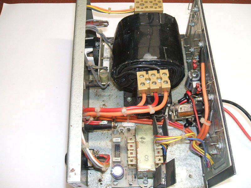
All heatsink positions are filled in the 300W model.
A close look at the insides showed that
the inverter was simply the 100W model with a larger transformer. Additionally,
there were now six MJ802 power transistors on the rear heatsink. Each side
of the transformer therefore is switched by three transistors in parallel.
The transistors are connected in parallel, but it does appear that the
links connecting the emitters to the PCB earth could function as emitter
resistors - thus ensuring equal current in each transistor. Otherwise,
it would be necessary to ensure the transistors were matched.
The back emf suppression network is slightly
different in this model. In the 100W model it's a 680R 10W resistor and
a capacitor of unknown value. In the 300W model, the resistor is 390R 5W
and the capacitor is 220uF 63V.
Internally, the inverter is the same as the late 100W model but
with a larger transformer.
The fault turned out to be very simple.
The switching relay was inoperative because the spring that holds the contacts
in the "off" position had broken due to corrosion.
A new spring fixed that, and the inverter
now worked as it should.
Finally, new 12V leads and battery clips
were attached.