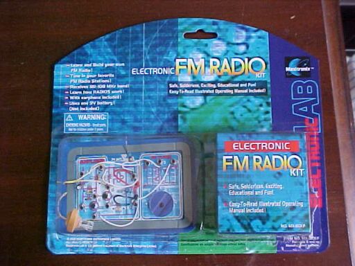
This is another example of a cheap FM radio
kit using a super regenerative tuner. The MX801F is one of the Maxitronix
series, and is similar to their MX901F and MX901AF. The notes in this article
are also of relevance to these kits. They were briefly mentioned
here
in my review of the Science Fair 28-234 AM/FM radio kit.
I had actually ordered the MX901AF in
view of it including the AM tuner, but ended up with the MX801F instead.
Not to worry, as I was primarily interested in how the super regen tuner
in this one worked and whether it was any better than the Science Fair
design. I ordered from Terrific
Scientific as it was local and wouldn't have to pay so much postage.
What surprised me is how small the chassis
was; 12x8cm. Like all these kits containing an FM tuner, the only construction
is related to connecting together the audio amplifier components.
Very cute little set once assembled.
I had it assembled in about an hour. It's
the usual spring connector construction on a cardboard chassis. This set
has a plastic surround to make it a bit more rugged. The 9V battery does
not have a holder on the chassis, but merely dangles on the end of its
lead.
The instructions were just as uninformative
as the Science Fair kit and contained some mistakes.
No technical description at all is given.
Following the instructions for assembly, several times I had to remove
the tuner from the chassis to proceed as the PCB covers the springs used
for the 9V battery connection. Obviously, no one checked the order in which
the construction steps were presented. Being of the present day, the earphone
is actually a ceramic type. It seems the crystal types originally used
in these kits are no longer. While it looks identical from the outside,
it's when you look down inside and see the flat diaphragm that you can
tell. While this type of transducer is of very high impedance like its
crystal counterpart, it does present a much higher capacitance. I measured
.035uF. This isn't a problem here as the earphone is driven by a low impedance
source, but for something like a crystal radio I would expect problems.
What was quite bizzare is the earphone lead is solid core wire! While it
is flexible enough, I wonder how often one can flex it before breakage
occurs.
Incidentally, I did test the completed
set with a crystal earphone and found very little difference.
Low audio output.
Upon powering up I was pleased to see
that the sensitivity was what it should be and the sound quality was far
better than the Science Fair kit.
Alas, the audio level was very low. It
was similar to a weak crystal set. While you could recognise music and
speech, it wasn't really of entertainment value, and hopless in a noisy
enviroment. Observing the waveform at terminal 8 showed a considerable
amount of quench signal but minimal audio. That is a sign of excessive
oscillation in the detector.
So, it looked like this one would also
require modification.
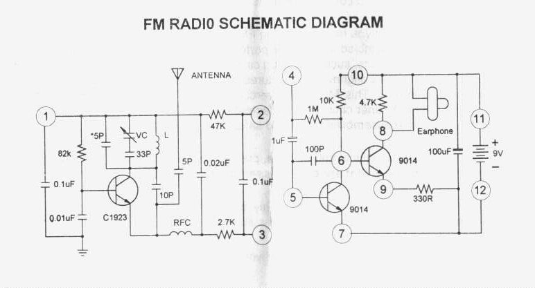
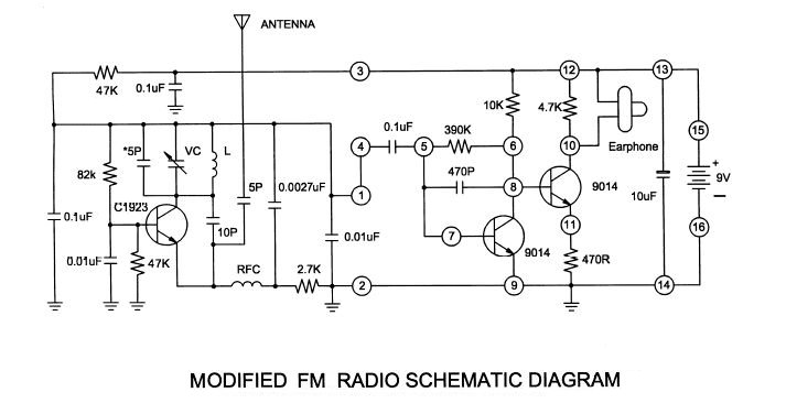
Circuit of the MX801F. Note the mistake with the 1M bias resistor
shown between terminal 4&6. It should connect from terminal 5 to 6.
Shown as above, the transistor receives no bias. The circuit on the actual
kit is correct. Terminal 3&7 are linked, as are 4&1 and 10&2.
During construction I noted that "MX901AF"
was printed on the tuner PCB, so obviously they use the same tuner in all
kits. However, there was one discrepancy. Instead of the 47K load resistor
shown above (between terminals 1&2), what was on the PCB, and what
is shown in the circuit for the MX901AF, is different. In the other circuit,
the load consists of a 10K and 22K in series with the junction of the two
bypassed to earth via a condenser. This condenser is shown below
as a .05uF, but on my PCB it was .1uF. Yet another difference.
The interesting question is why the change,
and which of the two circuits is meant to be the better. Obviously, two
resistors and one condenser are more expensive than one resistor, so I'm
inclined to think the MX901AF is the correct one. Assuming the MX801F was
developed before the MX901F this would also support this theory.
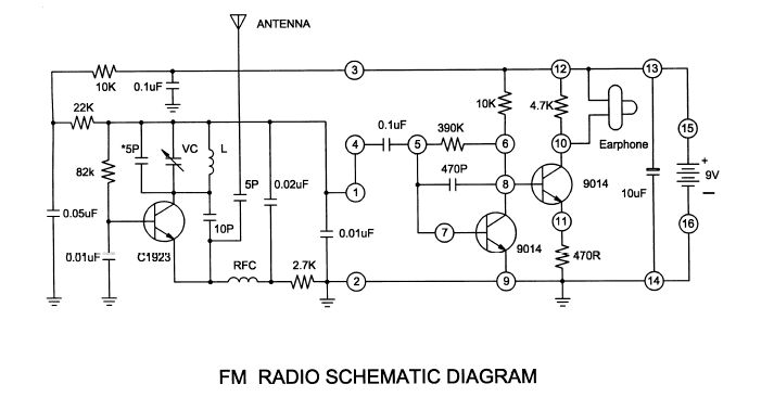
Circuit for the MX901F. Note the 22K and 10K. Interesting to note
slight changes to the audio amplifier.
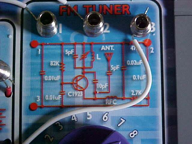
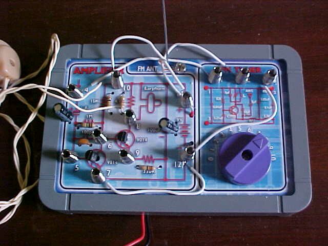
Unlike the Sceince Fair kit, this one shows the component values
of the VHF tuner on the chassis. Note the 47K resistor just to the left
of terminal 2.
The performance now was pretty good for
what it was, considering there is no user adjustable regeneration. In fact
the sensitivity is very good with only the 18cm long aerial. Quite a number
of Sydney's low power public radio stations are receivable at my location
in the mid Blue Mountains. However, audio quality appears to be somewhat
dependent on signal strength, with weaker signals being being less distorted
and easier to tune. I did find setting the detector bias level critical,
and the 47K base to earth resistor may need to be a different value with
other kits.
As I've explained elsewhere, a super regenerative
receiver provides highest output and most sensitivity just past the point
of oscillation. But, while weak stations are received optimally this way,
high power signals cause overload. This is when the detector needs to be
adjusted further into the point of oscillation to restore optimum sound
quality. Also, the ideal setting will vary from one end of the band to
the other.
As I've said I've had to compromise here,
and it's better to favour the weak signals.
One other thing is evident, and that's
hand capacitance. As the VHF tuning coil is right under the cardboard just
above where the knob is, there is a slight variation in tuning when removing
your fingers from the knob after tuning in a station. Touching the 9V battery
also has a similar effect.
A bit of shielding or a different layout
would have been worthwhile here.
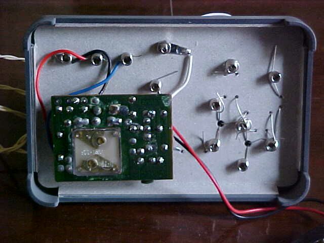
Under the chassis. Such an elementary circuit has incredible performance
for what it is.
Conclusion
This set is a considerable improvement
on the Science Fair model, even without modification. The audio is of quite
good quality.
However, to make it a practical receiver
to use all the time, it is necessary to modify the detector bias and quench
frequency. The supply voltage is also critical and the bias control really
needs to be adjustable. Hand capacitance is problematic.
Once again, it would have been useful and
informative for the intended constructors to explain the operation of the
circuit in a simple way at least. The fact that the FM tuner is preassembled
doesn't help one in learning anything about it. It appears that the kit
designers are incapable of getting super regenerative receiver design correct,
so they would be better off providing the tuner board with a TDA7000 type
of IC. Given how cheap the Chinese clones of this IC are now it wouldn't
increase the cost signifigantly. At least then good results would be guaranteed
and the constructor wouldn't be left with an unusable receiver. While I
have the experience to correct the bad design, the typical "For ages 8
and up", or non technical constructor would be at a loss.
Incidentally, by adjusting the relevant
trimmer on the back of the variable condenser, the receiver tunes
up into the aircraft band with very good results. So, if you are looking
for a cheap and simple aircraft band receiver, this kit is definitely worth
using.