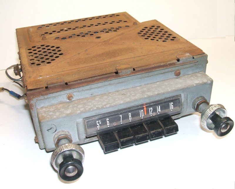
Volume and tone at left, tuning at right.
Volume and tone at left, tuning at right.
This radio was manufactured by Motorola
for various 1956 model Fords and is also known as the Ford model number
FDR-18805-B1. The particular set to be described came via a Model T acquaintance
who had obtained it while on a trip
to the U.S. Fortunately the knobs were
on the set - usually car radios are missing knobs and dial parts. In fact,
the set was complete except for one of the bottom covers, and also a 9
pin valve was missing.
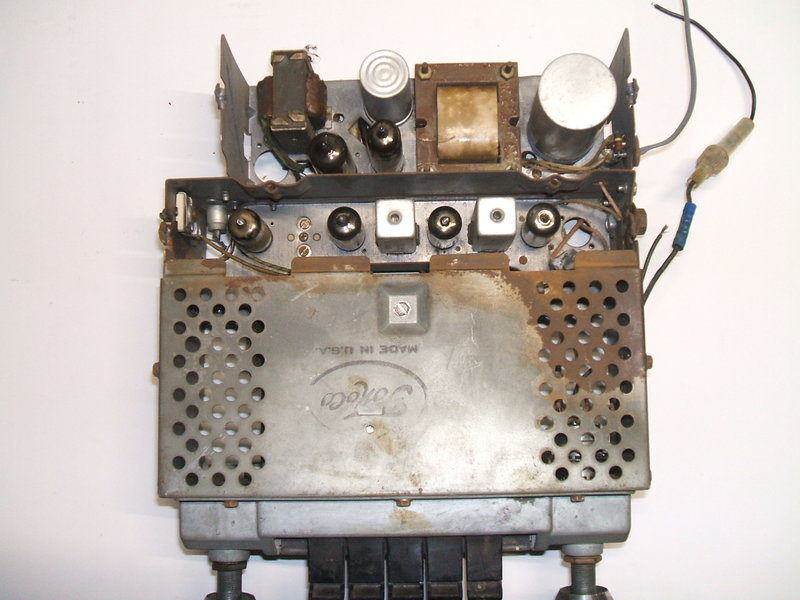
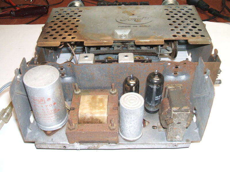
Bottom cover is missing but appears not to affect performance. Note
the FoMoCo stamp - Motorola is not stamped anywhere on the radio.
All the valves were miniatures, and the
vibrator was a Cornell Dubilier Electronics 12V type. This narrowed the
manufacture date to sometime between about 1955 and 1959, as Ford and other
U.S. car manufacturers had by now changed to 12V electrical systems.
From around 1959 most radios made for
U.S. cars were hybrid types. The valves were the standard line up; 12BA6,
12BE6, 12AU6, 12AV6, 12X4, but the missing valve had me curious. Obviously
it was the audio output, but a 9 pin miniature is unusual for this role
with a 12.6V heater.
The 12AB5.
Firstly a circuit would have to be obtained
to find out what the missing valve was. About the only place I could get
this from was Radiomuseum.org.
Here I obtained the Howard Sams circuit, and also a poor copy of what appears
to be the John Rider circuit. While some ebay sellers have the complete
manual, the postage costs reduce my enthusiasm for purchasing one. There
are also various Eastern European sites that purport to have circuit diagrams
and manuals, but my experience is you can never actually download anything
from them. Anyway, the valve turned out to be a 12AB5. I had never heard
of this valve and it had certainly never been used in any Australian car
radio. In the 1950's and 60's there ware a lot of new American type numbers
introduced, which were improvements on existing types, and no doubt the
12AB5 was one of these. I was curious why they didn't just use a 12AQ5
or even a 12V6. After all, an audio output stage for a radio is nothing
complicated.
As it happens, the 12AB5 appears to be
based on the 6V6 and its equivalents. The operating conditions are the
same. However, what makes it different is the data specifically mentions
operation in car radios with a supply of 10 to 15.9V.
It would appear that the 'improvement'
over the 6V6/6AQ5, etc. would be to reduce the possibility of grid emission
at high heater voltages.
There is actually a 9 pin equivalent of
the 6V6, the 6BW6, but this was a British valve not used in U.S. designs,
and it never had a 12.6V heater version.
What to do? While the 12AB5 was undoubtedly
popular in the U.S., it certainly wasn't here. Of course, they're a dime
a dozen on the U.S. ebay, but the thought of paying about $30 postage just
to get one here put me off that idea. Various schemes went through my mind
- replacing the socket with a 7 pin type and using a 12AQ5, rewiring the
socket and using a 6BW6 with a resistor in series with the heater, or even
using a 12BY7 and accepting reduced output.
Just maybe I had one in my valve collection,
since I do have a few less than common U.S. types. Much to my surprise,
I had not just one, but five 12AB5's in my car radio section of the collection.
Where they came from I can't remember, but they were all new in boxes.
That solved that problem nicely and I
could begin restoration.
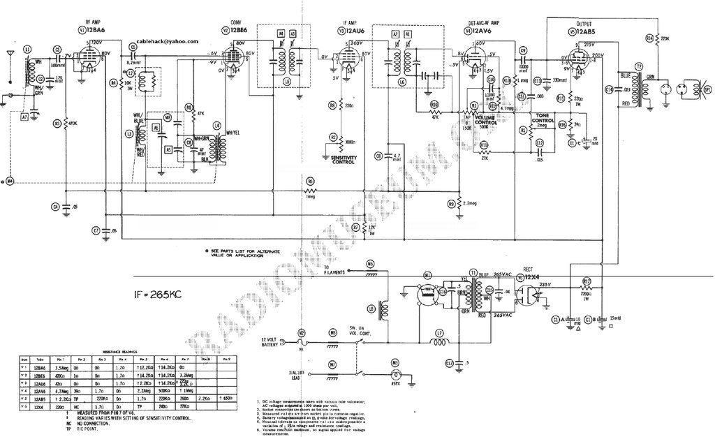
Note! There are mistakes on this circuit diagram regarding the AVC
feed and 12AB5 cathode bypass.
RF Amp & Converter.
As one would expect, the aerial input
socket is the ubiquitous and now standard Motorola type. This is nice to
see after dealing with various bayonet and screw type plug connections
used for many other car radios of the era. While there is nothing electrically
wrong with such connectors, the plugs are now obscure.
There is an RF amplifier using a 12BA6
in the conventional way. As the aerial is connected directly to the first
tuned circuit to provide maximum coupling, its capacitance affects the
tuning range. Therefore, as is typical, a trimmer capacitor is provided
to compensate for different aerial capacitances. The 12BA6 plate load is
actually a 10K resistor and this feeds the 12BE6 converter. Resistance
coupling of RF amplifiers in car radios is not that unusual. In Australia
it was used by Astor and AWA at least.
The second RF tuned circuit is connected
to the signal grid of the 12BE6. It is unclear what the series choke with
shunt resistor is for, but it can be assumed the choke requires the resistor
to lower its Q. The oscillator circuit for the 12BE6 contains nothing unusual
being a typical cathode feedback type circuit. Perhaps the only non standard
thing here is the 47K grid resistor is not returned to earth directly,
but instead through the oscillator coil secondary. Electrically, this should
make no difference to operation.
IF Amplifier.
This is the first unusual aspect of design.
A 12AU6 is used in a fairly conventional circuit, but there's a number
of interesting aspects. Firstly, the 12AU6 is a sharp cut off pentode.
Thus, it is not suitable for an AVC controlled amplifier, except in a limited
way. High AVC voltage applied to a sharp cut off pentode can result in
distortion, as the valve is taken out of linear mode and into class B.
For this reason, remote cut off types are normally used. As it happens,
there is no AVC applied. This is unusual, and in this set AVC is applied
only to the RF amplifier and converter stages. One can assume that the
range of control provided is sufficient, with the limited signal pickup
helping. Perhaps strangest of all is the so called "sensitivity" preset
in the cathode circuit. Note also, that the 220R cathode bias resistor
is not bypassed. Since the 12AU6 is a high gain valve, we can assume this
was done to keep the stage stable by providing a degree of degeneration.
The sensitivity control is a 3K rheostat which provides further degeneration
(and increase in bias). Why this was included in a car radio of all things
is very strange. That is the last kind of receiver, which with its short
aerial, you would want to desensitise. Not only that, the control is a
preset not accessible as a user control. Similar sensitivity controls were
included in some domestic sets around the late 1930's - early 1940's, and
were sometimes labelled as a "noise suppressor". (The Kriesler 710A console
from 1937 is one such set in my possession). The idea was that the control
would be backed off so that the IF amplifier was operating with less gain,
and only the local stations were receivable. The so called "noise suppression"
comes about simply because a low gain amplifier is less noisy that a high
gain one, and any interference will also be subdued. In practice, it is
a gimmick and has no effect on electrical noise, if it has similar or greater
amplitude than the wanted signal.
No information was included in the alignment
instructions as to how this control should be adjusted in the 66MF.
265Kc/s IF.
In this receiver, the IF is 265Kc/s. This
is not uncommon for portable and car sets, because a higher gain and better
selectivity can be obtained than at 455Kc/s. In the early days of superhet
receivers, low IF's such as this were common, but there's two reasons they
went out of fashion for domestic sets. Firstly, the selectivity can be
too great and the demodulated audio is restricted in bandwidth. Also, double
imaging is more likely to occur. That is, a particular station, if strong
enough, might appear at two places on the dial. The possibility of this
increases the closer the local oscillator is to the station frequency;
i.e. as the IF is reduced. To explain this, let's revise some basic superhet
theory. Forgetting any tuned circuits at the RF input, the receiver will
respond to a signal that is the local oscillator frequency plus or minus
the IF. For practical reasons with MW receivers, the local oscillator operates
on the high side; i.e. above the receiving frequency. Selectivity of a
superhet is largely determined by the IF amplifier. The RF input selectivity
is broad by comparison.
Now consider a station at 1100Kc/s. For
an IF of 265Kc/s, the oscillator will be at 1365Kc/s. That is the received
frequency plus the IF. Now, if the oscillator is operating at the IF less
than the received frequency; i.e., 835Kc/s, the same station will again
be received. Normally when the local oscillator is at 835Kc/s, the radio
would be receiving 835 - 265, or 570Kc/s. Thus, the wanted station appears
correctly on the dial at 1100Kc/s, but also at 570Kc/s. Further thought
will reveal a problem if there is actually a station on 570Kc/s. A heterodyne
whistle will be the result.
In theory, the RF tuned circuit at the
aerial input should prevent reception of an 1100Kc/s station with the dial
set to 570Kc/s. However, anyone who has experimented with simple one tuned
circuit receivers, such as a crystal set, will know that selectivity is
limited in practice, and worsens as signal strength increases. In fact,
if the signal is strong enough it will be received over the entire tuning
range.
With car and portable radios, the aerial
pickup is naturally very limited, so the problem is not likely. With domestic
receivers operating with a long wire aerial, and a high signal input level,
more than one tuned RF circuit is often required to eliminate the effect.
Why does a higher IF such as 455Kc/s reduce
this double imaging effect? Simply put, the further the local oscillator
is away from the received frequency, the more effective is the RF input
selectivity. Also, the image frequency is more likely to be out of band.
Going back to our example of the 1100Kc/s station, if this is received
on a set with a 455Kc/s IF, the local oscillator is now 1555Kc/s. The same
station would also be received with the local oscillator at 645Kc/s. This
can't happen in practice since the L.O. operating at 645Kc/s would be for
a receiving frequency of 190Kc/s which is well below the MW band. In fact,
practical constraints prevent the local oscillator tuning down that far.
Assuming the lowest frequency to be received is 530Kc/s, the lowest L.O.
frequency is 985Kc/s.
From this discussion, it should be evident
that the choice of IF is not just a random number, but chosen to suit the
tuning range of the receiver, and the station frequencies to which it will
be tuned.
Detector, AVC, & Audio.
Next, we come to the first mistake on
the circuit diagram. The AVC is developed in the usual fashion with one
of the 12AV6 diodes shunt fed via a capacitor from the 12AU6 plate. This
is decoupled by a 1M resistor which feeds the RF and converter stages.
Filtering is by a 0.05uF condenser as normal. The diode load resistor is
2.2M. The error is that the shunt feed condenser is shown to be fed from
the B+ line and not the 12AU6 plate. There is no way any kind of negative
voltage could be developed that way, and even if it could, it would not
be dependent on signal strength. The actual set wiring, and also the Rider's
circuit diagram show the correct connection. Strangely, the shunt feed
capacitor is only 4.7pF. That is considerably less than the normal 50-100pF
used here. It would appear the design was intended to restrict the amount
of AVC voltage developed.
The set has delayed AVC by virtue of the
12AV6 cathode being set at 1.5V. This means the diode has to have more
than 1.5V applied before it conducts and starts producing the negative
AVC voltage. This is standard practice on anything but the cheapest receivers,
so as to prevent the receiver being desensitised on weak signals. The reason
this comes about is because if the AVC is not delayed, there will always
be some negative voltage produced because of atmospheric noise, and also
noise generated in the preceding stages of the receiver.
This permanent negative voltage fed into
the AVC line therefore desensitises the receiver when tuned to a weak station
- which is the opposite of what is required. Delayed AVC prevents this
happening by not enabling the AVC diode to conduct, until the signal has
increased to something above the noise level.
Some very cheap receivers without delayed
AVC actually rely on the noise level to provide the initial bias for the
IF amplifier, thus dispensing with its normal cathode bias resistor and
capacitor. It's a crude system, and the IF amplifier valve can have a short
life when the set is tuned to weak stations if the noise level is not sufficient.
The detector circuit is standard with the
other 12AV6 diode providing this function. A standard RC filter removes
most of the IF, with the resultant audio across the volume control, which
also functions as the diode load. So that the detector diode is not desensitised,
the earthy end of the volume control is at the same potential as the 12AV6
cathode. If it was taken directly to earth, the received signal would have
to be strong to overcome the 1.5V bias otherwise on the diode.
The volume control is tapped for loudness
compensation (i.e. to compensate for loss of bass response in the human
ear at low volume), and the tone control is also part of this circuit.
With the tone in the "low" position, the
0.003uF condenser in the 12AB5 grid circuit is shunted to earth, and the
0.05uF in the loudness control is shunted across the loudness tap. Thus,
there is a predominance of low frequency response.
When the tone is set to "high", the 0.003uF
has 2M of resistance in series and has little shunting effect. The 0.05uF
is shorted out, so the loudness circuit no longer boosts the low frequencies
at low volume. Obviously, varying degrees of frequency response are obtained
with the control in intermediate positions.
The 12AV6 triode performs as a the first audio amplifier in the usual way. It uses contact bias by virtue of the 10M grid resistor. If a valve is of such construction that the grid is close to the cathode (such as a high mu triode like the 12AV6), electron emission from the cathode is sufficient to cause the grid to go negative by itself. If there is no resistor to the cathode, the amount of bias may cut the valve off. Values of grid resistor are typically 4.7M to 22M for this kind of bias. If the resistor is too low, the electrons leak away too quickly, and the voltage developed is too low. The plate load is 1M which is rather high; normally 220K to 470K would be used here.
Audio Output.
As mentioned previously, this uses the
not so common 12AB5, but operating conditions are quite standard. Negative
feedback is obtained by returning the 220K grid resistor to the speaker
voice coil in the inverse phase. 220K is appropriately low to reduce the
effect of grid emission, particularly when the heater voltage is higher
than normal.
However, somewhat unusual is that while
220K is a legitimate choice of grid resistor, the preceding plate load
is 1M. This results in some loss of gain since maximum power transfer cannot
occur. It is pleasing to see a ceramic condenser used as the grid coupler,
and not a paper type.
The next mistake in the circuit diagram
concerns the cathode circuit of the 12AB5. It operates with normal cathode
bias, comprising the 220R and 39R in series. The mid point connection provides
the source of AVC delay voltage. The mistake is that the 20uF bypass condenser
is shown connected across only the 39R. It should be connected across the
220R as well. As shown, the circuit would work, but with less gain. There
is already a negative feedback circuit, so using cathode degeneration is
not required for this function. The actual set wiring is correct, as is
the Rider's circuit diagram.
The speaker is connected by a small 3
pin phenolic plug and socket. The pin configuration is non-standard. Not
shown on the circuit is also a ceramic condenser from the speaker voice
coil output to earth. The purpose is to reduce RFI coming back into the
set via the speaker wiring.
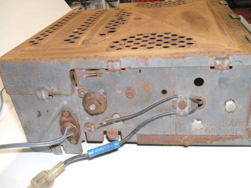
Speaker plug is visible. Supply and dial light connections feed
straight in.
Power Supply.
This uses a four pin non-synchronous vibrator
with a 12X4 rectifier. The vibrator socket is wired so that either shunt
or separate drive types can be used without alteration. Fitted to the set
is a CDE type C-4 which is shunt drive.
There is no spring loaded grounding cup
to secure the vibrator and earth the can. The vibrator is lightweight with
an aluminium can so isn't likely to fall out. Evidently, the non-earthed
can does not cause RFI with this set design.
Timing condensers are provided across
both the primary and secondary of the power transformer. Note that the
secondary condenser is connected from one side of the secondary to earth;
not across the whole secondary as is commonly done. This reduces the voltage
stress considerably, but the value of capacitance has to be higher. An
interesting feature is that the transformer centre tap is returned to the
12V supply and not earth. This provides a free extra 12V on the B+ supply.
It is surprising more vibrator powered equipment does not do this, but
it does mean the radio can only be used with a negative earth supply. Running
this radio with a positive earth would actually reduce the B+ by 12V.
The B+ filtering is standard with two
electrolytics and a series resistor.
Power supply and audio output are shown here. 12X4 is at left, and
12AB5 at right. The can electro was dried out.
The 12V supply is protected with a 5A 3AG
inline fuse. As is typical with Ford, the dial lamp is fed separately from
the dash light circuit. This means the radio dial lights up only when the
park lights come on. Dial light life should be a lot longer therefore,
as the bulb is only operating if the radio is switched on, and the park
lights or headlights are also on. My experience with car radios is that
the dial lights serve no function during daylight and are seldom visible.
Both the 12V radio and dial light inputs
are filtered with "spark plate" capacitors. These are low value, but low
inductance, capacitors which reduce ignition interference coming through
the supply inputs. Construction is simply that of a metal plate separated
from the chassis by a sheet of mica or paper.
Two new 22uF 350V electros replaced the
dried out filter caps. A three lug tagstrip had to be installed to accommodate
them, but there was plenty of room, and one of the speaker transformer
screws provided a convenient mounting point. Although some people do it,
I do not recommend just connecting new capacitors across dried out originals.
It's particularly tempting with can types as there are usually no other
tagstrips nearby to connect the replacements to. The danger is if in the
future the dried out capacitor breaks down.
The timing capacitor was replaced with
a pair of 0.022uF Philips polycarbonate types with a 1600V rating. For
this circuit, 630V types would be OK. While the value is not exactly 0.04uF
as per the original, it was on the higher side, which, given a choice,
is better than a lower value. Anyway, the waveform would be checked to
ensure the replacement was suitable. The 0.5uF primary buffer was also
replaced. Even though this capacitor is across the transformer primary,
it is exposed to much more than 12V. Surprisingly, things were not well
when I powered up again!
Capacitors replaced.
Vibrator.
The vibrator sounded distressed, and the
waveform was awful with lots of high voltage spikes. Clearly something
was amiss, but what? It appeared the timing capacitance was insufficient,
and indeed, using 0.056uF instead gave a good waveform.
I had noticed previously that the vibrator
sounded distressed for the split second it takes to come up to normal frequency.
With some transformers, shunt drive vibrators will not start properly if
there is insufficient timing capacitance. Insufficient timing capacitance
is the same as saying the contact gap is too wide since the duty cycle
is now less. As I was beginning to suspect, the vibrator contact
gap had increased slightly. Sure enough, the vibrator did not start if
the input voltage was gradually raised. It would only start with a sudden
application of voltage. When this happens, it means the contact gap has
increased whereby the contact is not making connection with the reed weight
directly opposite the pole piece. Also, the voltage required to get it
to start this was was around 10V. This further confirmed my suspicion.
In this condition, sudden application
of supply voltage will start the vibrator because the reed weight inertia
will swing the reed further past the pole piece.
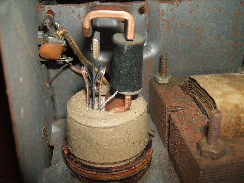
Last of the CDE vibrators were very simple and compact.
Time to open the vibrator and have a look.
The thin aluminium made the job of peeling back the base crimp not too
difficult and the damage was minimal. The contacts were in excellent condition
and it appeared the gap had only increased from the hammering, rather than
any electrical wear. This vibrator is of the last generation of the technology
and is a very nicely designed simple and compact unit. There are no tungsten
buttons on the reed, but instead the reed material is the actual contact.
Tungsten buttons are still present on the fixed contacts.
A slight tweak of the contacts brought
them back to where they should be, and the waveform was now correct with
the new buffer condenser. Had the vibrator been a separate drive type,
the contact gap could have increased without affecting the starting. The
only thing to watch out for then is that the timing capacitance is still
sufficient.
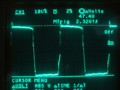
Vibrator waveform across the transformer primary. The primary buffer
has around 47Vp-p across it.
12BE6.
With the power supply now working, some
stations could be received, although very weakly. Sensitivity was very
poor. I had noticed the 2K filter resistor for the B+ had been overheated
in the past, and curious I checked the B+ voltage which was a bit low.
Something drawing excess current in the front end would be the likely cause.
When I measured the AVC, I was surprised to see +2.4V, even on a strong
station. The AVC of course should never be positive. When this was shorted
to earth, performance immediately improved to something more normal. Where
could the positive volts be coming from? A likely source is a leaky AVC
feed capacitor from the IF amplifier plate. The 4.7pF was disconnected,
but the volts were still there. Next, I had a look at the tagstrip with
the 0.05uF AVC filter connected to it. The adjacent tag was a B+ connection,
so if the insulating material was leaky it could be the cause of the problem.
Except it wasn't when I isolated the AVC from that tag. I wondered about
the tuning unit in case there was some kind of leakage there, as the RF
input coil is connected to the AVC. Disconnecting that didn't get rid of
the volts either.
I had noticed that the positive volts
always appeared soon after the B+ had come up, not at the same time. That
led to suspicion the problem was actually grid emission from one of the
AVC connected valves. It didn't take long to find the 12BE6 was the cause,
and another one installed brought forth negative AVC volts and normal performance.
At this point I replaced the AVC filter as it was a paper type, and also
the screen bypass in case it became leaky later on.
Tuning Unit.
A clean up and lubrication of the tuner
got the push buttons working, but the clutch needed work. The rubber clutch
surface had gone brittle, was breaking up, and had become detached from
the drive gear. In units of this type I've seen before, the clutch surface
has often been cork. A suitable replacement might be cork gasket material,
but I didn't have this so used rubber cut from a bicycle inner tube. This
was contact cemented into position and looked good. Unfortunately, there
was some slippage and I took the easy way out and applied some belt anti-slip
compound to the rubber. Evidently, the rubber I used was did not have enough
friction. I have seen at least one radio where the clutch had been glued
together to stop it slipping. This is bad practice, since the tuning mechanism
is not protected if someone keeps turning the tuning knob past the end
of the dial. It also prevents the push buttons working properly.
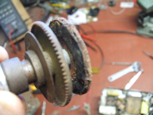
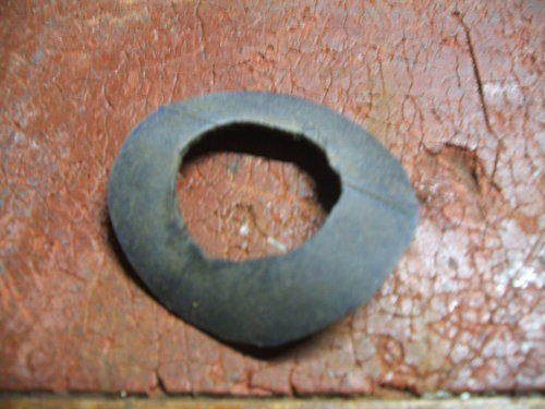
Tuning clutch was in poor condition. New clutch surfaces were made
from rubber.
Getting access to the clutch was awkward, but after doing it three times, I became quite adept at it. The front part housing the dial has to come off, then the front/bottom cover plate. The tuning unit is then detached by four screws behind the dial and one underneath. Once that's done, the clutch is removed by three screws on the side of the tuner. When replacing it, it's necessary to reset the anti-backlash mechanism. This is the standard set up with two sets of gear teeth side by side, spring loaded in opposite directions so there is always pressure on the drive gear teeth.
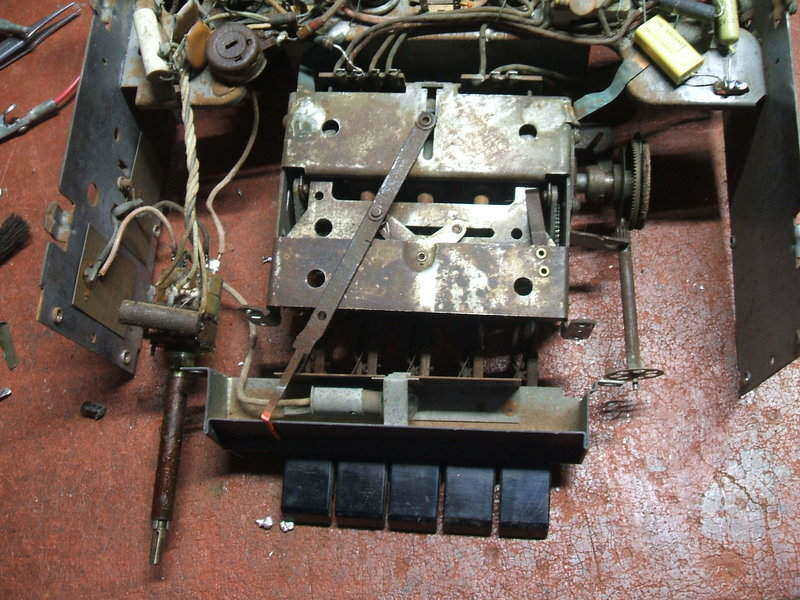
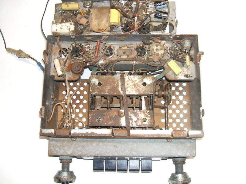
Tuning unit exposed for service. The sensitivity preset is visible
to the top left of the tuner.
Audio Output.
Given the defective B+ filter caps, and
that the cathode bypass for the 12AB5 was in the same can, suspicion fell
upon this also. Bridging it with a 22uF electro brought up a bit more volume,
along with more bass. Again, the original was disconnected and the new
one connected in its place. It was also an opportune time to replace the
overheated cathode resistor - a result of a previous faulty 12AB5?
One of the unused pins on the 12X4 socket
had been used as a tie point for the junction of the 220R and 39R. It's
a convenient thing to do by the manufacturer, but the danger is if a replacement
valve is fitted that does have a connection to this pin. I left it as it
was since there was no other convenient tie point, and besides, only I
would ever service this radio.
Replaced parts.
Performance.
In my workshop the set suffers badly from
electrostatic interference. I had this problem with the Detrola
6R. Not all car radios suffer from it, and I can only put it down to
the RF input circuit design. When I tried a tuned loop aerial, the improvement
was quite marked with the interference largely gone.
Away from the interference, the 66MF performs
adequately but is not a super-DX set. Not surprisingly, the sensitivity
preset is required to be set at minimum resistance. Sound quality is noticeably
good however, and the feedback and loudness circuit is very worthwhile.
Current consumption is very low at just over 2A.