When you consider what valve amplifiers cost these days, $299 seemed unusually low cost.
In their 2008 catalog , I was interested
to see that Jaycar was going to start selling a valve amplifier sometime
later in the year. The price looked very attractive, and the amplifier
itself looked like a nice compact unit. By August 2008, the amplifier had
become available.
The story of this amplifier is fairly
well known to Australian and NZ enthusiasts, but to explain to overseas
readers, Jaycar is a chain of electronics stores selling components and
built up products. The valve amplifier is a generic Chinese design sold
under various names around the world, in this instance under Jaycar's "Digitech"
brand.
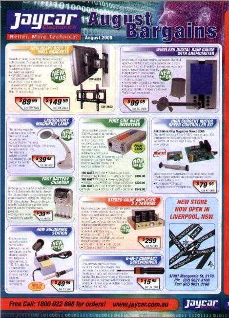
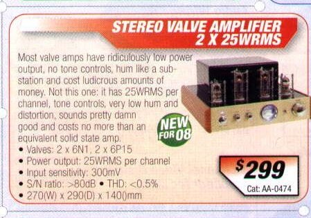
When you consider what valve amplifiers cost these days, $299 seemed
unusually low cost.
25W from a single pentode? Not likely!
Obviously it's a Chinese built unit, which is fine. But look at the valves. Two 9 pin output pentodes which are equivalent to 6BQ5/EL84. 25W per channel from a valve that can only give out about 5W? I thought they must have rated it like computer speakers that supposedly give out 100W from their 3" drivers with the whole lot powered off a 12V 200mA plugpack. Still, the sales staff insisted that was correct. But having being around valves, and having designed, built and repaired equipment using them for a good proportion of my life, I knew that no normal 9 pin pentode or beam tetrode could give that sort of power, so just took it with a grain of salt. That was fine by me; I was attracted to this amplifier because of its price and would be happy with 4 or 5 watts per channel. Despite first appearing in the 2008 Jaycar catalog, it took until late August for the amplifier to appear in the stores (see the above advertisment), so I eagerly purchased one when they finally became available. The sales staff were enthusiastic about the amplifier, and despite the quality of the speakers used with the demonstration model, it seemed to sound OK, though I sensed something wasn't quite right. The bass response seemed rather good for a low power single ended amplifier; too good in fact. Maybe they used really good output transformers I thought.
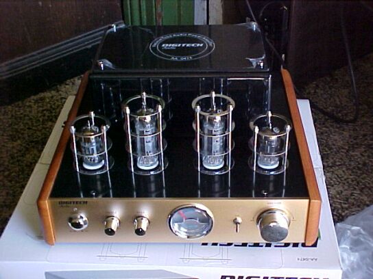
It's a very nice looking unit. The single VU meter is obviously cost cutting, but I could live with that.
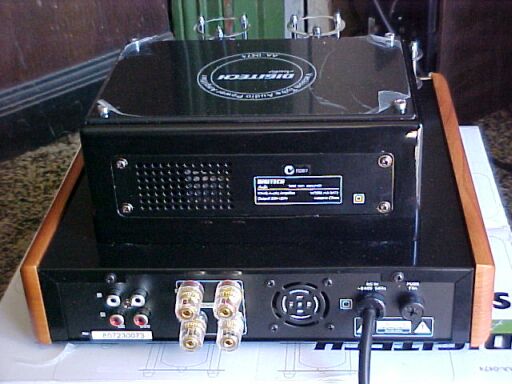
A fan in a low powered valve amplifier? That was a surprise. There isn't much to dissipate heat under the chassis of a valve amplifier. I know it's trendy to have fans in things these days, or maybe they had regulators for the heaters or high tension supply. Only two inputs are provided. A bit limited given my two tape decks, tuner, and CD player. Still, I could make up a control unit with switches which wouldn't be a major undertaking. And by the way, don't bother undoing the hex head screws on top of the transformer enclosure; there's nothing under the top plate.
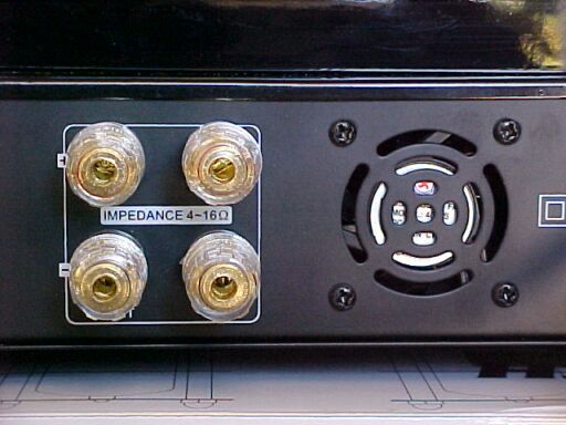
4-16 ohms with no provision for changing transformer secondary taps? That seems a bit odd as valve amplifiers really do need to have the speaker voice coil impedance matched, otherwise the output valves do not see the correct load, and distortion as well as reduced power will result. And there's that fan again.
![]()
I'm starting to smell a rat now. Only one transformer lives inside the enclosure above the chassis. Maybe the speaker transformers are under the chassis.
![]()
What!? A 32V centre tapped transformer. No 250V winding to be seen. My next thought was they must use a switchmode supply or another transformer under the chassis. A switchmode supply would explain that fan. This one must be just for the valve heaters. Time to see how the 250V supply is obtained and to have a look at the speaker transformers...
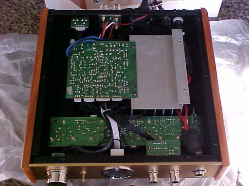
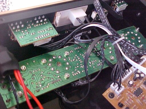
Hmmm...don't see any speaker transformers here. Surely they're not under the aluminium thing or that square PCB. The odour of the rat is getting stronger...
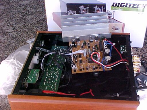
Still no speaker transformers to be seen. Why all that solid state stuff just for a regulated power supply? Let's take a closer look.
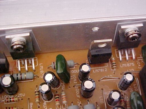
Well, you know what the feeling of a sinking
heart is like? That's how I felt when I saw a pair of LM1875's and knew
very well they are audio power amplifier IC's.
I couldn't believe I'd been conned like
this...but the ad did say "Valve Amplifier". So that's how they get 25W
per channel! No wonder we had a fan cooled heatsink!
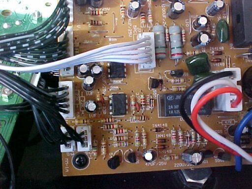
A further look around shows the speaker relay to hide the power up thump which is unique to solid state amplifiers. The two IC's look like op amps...
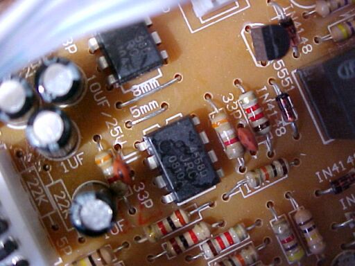
Ah yes, 4558's. Obviously to feed the LM1875's. Why bother with the valves?
I didn't bother removing the valve PCB
but doesn't look like much of a component count there, considering each
channel has two triodes and a power pentode. Yeah, a power power pentode
feeding a solid state op amp. What a joke! Well, I guess it's justifiable
given the low plate voltage, but somehow I think power pentodes were chosen
purely for visual effect. Just to be sure the valves actually had more
than just the heater pins used, I did unplug them and the signal did vanish
(though not the hiss from the solid state output stage), so the valves
are in the signal path but obviously each stage has an extremely low gain.
Subsequent circuit tracing revealed the pentodes were wired as triodes,
and connected in parallel with one section of each of the twin triodes.
The other triode sections are not connected and are purely visual in their
function.
When I was trying the amp, I thought the
valve heaters looked rather bright and they seemed to warm up faster than
I was used to. Maybe these Chinese valves just had bright fast heating
cathodes. Surely they aren't over running the heaters for visual effect
(after all, a major reason valve amplifiers are sought after by the technically
ignorant is the warm glow of the valves, with the actual performance being
of secondary importance). Let's just run one off 6.3V and see...
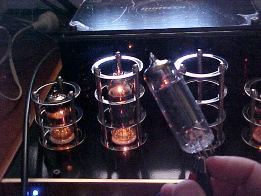
Here we have one of the output valves in my hand running off 6.3V from a bench supply. That looks more like it. Now look how bright the same valve is in the amplifier! Better measure the voltage now...I'll put the DMM across pins 4 and 5 with the valve plugged in...
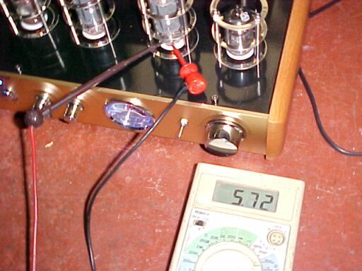
Strange reading. I'm getting only 5.72V but the valve heaters are so bright. And I get readings on both AC and DC too. Time to check with the CRO.
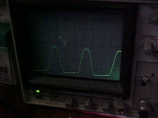
All explained now. They're using the 16V
transformer winding in series with a diode to function as a dropper. Here
is a 19V peak half wave rectified sine wave to feed the heaters. The idea
is that by chopping off half the sine wave is that you feed half power
into the load (valve heater). It's a common technique used in series heater
valve television sets to reduce dissipation in the heater dropper resistor.
The technique is described
in detail here.
This is the waveform showing 5.72V
DC on the DMM. The RMS value is closer to 8.5V. No wonder the valves light
up so bright! Somehow I don't think they're going to have a very long life
run like that. Valve heaters are generally meant to be run within 10% of
the published rating (in this case 6.3V).
In one way I thought it was a highly amusing
fraud by the Chinese manufacturer, but also felt it was an example of false
advertising. I had ideas of actually gutting all the solid state circuitry,
and wiring up the valves to be used in the correct way and fitting proper
transformers. However, $299 just for a chassis, front panel, and some cheap
common type valves, and then having to buy more transformers and other
parts was not economically viable. I can build a valve amp from scratch
for a lot less.
I did have ideas of keeping the amplifier
just for its appearance, but not only do I not need another solid state
amplifier; I don't need to pay $299 for one.
Needless to say, I quickly returned the
amplifier to the store for a refund. They were very good about that and
asked no questions, though I did explain my observations in a constructive
way to help them understand why I was returning it.
Moral of the story? Never buy a new valve
amplifier without actually checking what it really is.
What Really Went Wrong.
After returning the amplifier, I mentioned
my findings to Silicon Chip
who informed me that they'd heard from another reader with the same experience.
The editor contacted Jaycar who quickly
corrected the advertisement on their website. The ad now stated the amplifier
is solid state with a valve preamp. There is no objection to this amplifier
being sold with the correct description, as there are people who like the
look of valve equipment, even if it is full of solid state, However, the
heater voltage does need to be corrected.
The next time the amplifier was advertised
in Silicon Chip was in November 2008.
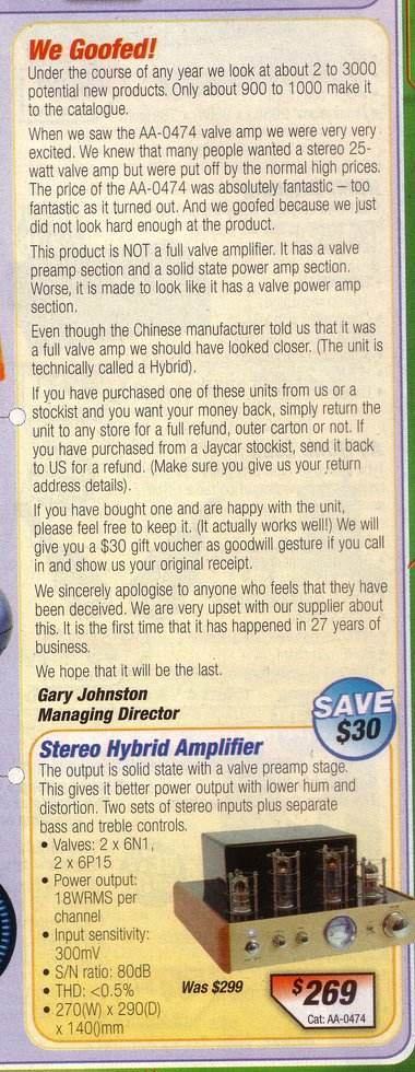
Updated advertisement explained what went wrong.
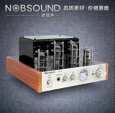
A remarkably similar amplifier in appearance, although the transformer
enclosure is larger. The headphone socket is not fitted to the Jaycar version.
How to correct the heater voltage.
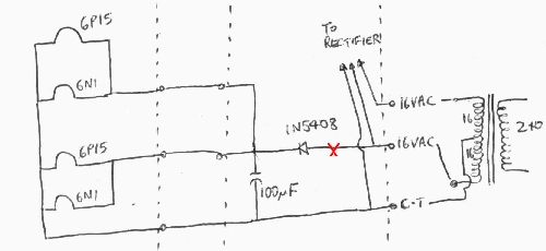
Heater circuit in its original form. Resistor to be added at point
"X".
I have had enquiries about how to reduce
the heater voltage to the correct 6.3Vrms. Having now obtained another
amplifier for a tenth of the original cost, I decided to trace out the
circuit and find the required value for the dropping resistor. As described
previously, a 1N5408 acts as a dropper by removing half the power (not
half
the voltage!) fed to the heaters. The 100uF appears to be superflous.
With the current drawn being over 2A, such a low value of capacitance has
no smoothing ability. I can only assume it may have been incorporated to
prevent the diode switching transients being fed into the heaters (given
that the valves are at the input stage). In this case we certainly don't
want a smooth DC supply!
Examining the formulas shown on the heater
dropper page, we can see that the valves will receive .707x (16-700mV),
or 10.8Vrms. That's why they glow so bright and warm up so fast. The simplest
way to restore the correct 6.3V is to put a resistor in series with the
dropper diode. The value turns out to be 1 ohm, and needs to be 20W. It
gets hot! As 10W resistors are easier to get, use 2x 2.2R 10W in parallel.
There is enough room inside the transformer enclosure to mount them there
on a tagstrip, or other moderately high temperature terminal strip. The
problem with the diode dropper method is the transformer is being saturated
because of the high DC component in the secondary winding. That makes it
inefficient and unneccessarily warm. We can improve on this considerably:
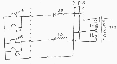
Improved heater circuit is much more efficient.
It is quite simple to separate the heater
circuits for the left and right channels as they are run separately in
the 5 way white cable between the two PCB's.
By using separate dropper diodes and capacitors,
and using both halves of the transformer secondary we eliminate the DC
in the winding. Plus, the load is equally balanced. Here, the dropper resistors
are 3R 10W. You can make this from two 1.5R 5W resistors in series. An
extra diode is needed, and again this should be a 1N4508. The easiest way
to do the mod is to cut into the 5 way cable and bring the heater wires
to a tagstrip, with the resistors and diodes mounted on it. Then run wires
to the 16V (blue transformer wires) connection on the main PCB for the
supply.
Switch on, and the heaters should run
a lot less bright! Note that if one valve is removed, the others will receive
higher heater voltage because less current flows through the dropper resistor.
Note that ordinary meters give an erroneous
reading when measuring the half wave sine wave produced by diode droppers.
You need to use a CRO or true RMS meter. With a CRO, you want a peak of
12.6V, where the valves receive 6.3Vrms.
Ultimately the best heater supply is to simply wind on a 6.3V winding on the existing transformer. Turns per volt is about 4.5, so for 6.3V try 29 turns to start with. It may be necessary to include an extra turn or so to compensate for losses under load. At least you can use a normal meter to check the voltage! Wire could be something around 18-20 gauge enamelled copper wire.
I have had a few emails asking how to connect the resistors from non technical readers. Unfortunately, as I no longer have the original PCB, and that it seems two different kinds of PCB were used, I cannot simply show where to cut tracks, etc. The person wishing to undertake this work needs to have the skill to be able to trace out the heater supply in their particular amplifier.