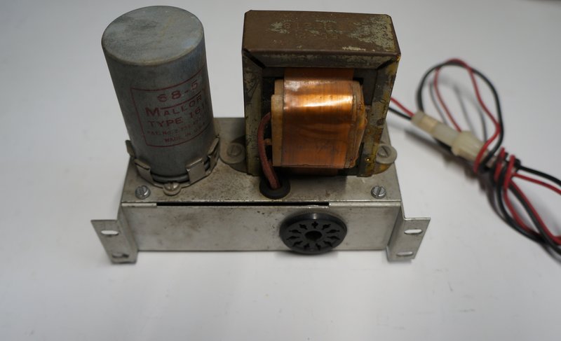
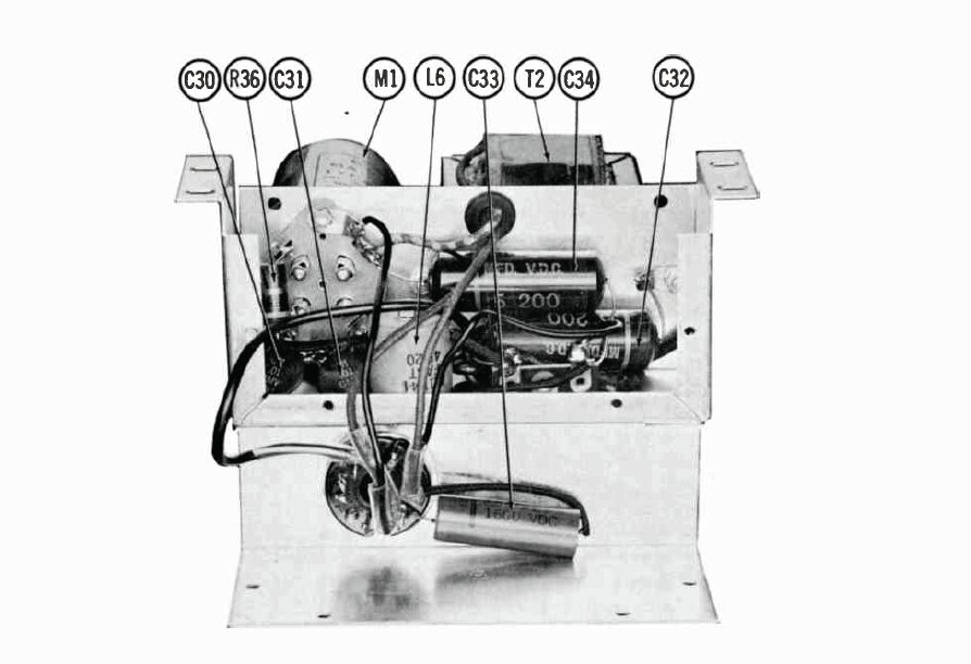
Note the four mounting holes for attaching to the rear of the CB transceiver.
Note the four mounting holes for attaching to the rear of the CB
transceiver.
As far as Heathkit vibrator power supplies
are concerned, the GWA-12-1 would probably be the least common. It was
specifically designed for use with the GW-12A CB transceiver. There is
very little information about it, and it was only whilst browsing through
a sellers other items on eBay, was this example found and purchased.
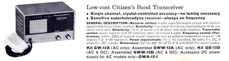
The GWA-12-1 allows 6 or 12V operation of the GW-12A transceiver.
The GW-12A is a single channel CB transceiver
from the early 1960's. The above advertisement is from the 1963 Heathkit
catalog. Like many other Heathkit transceivers, it can operate from 117V
mains, or with an optional vibrator unit, 6 or 12V DC. A multi pin plug
is provided on the back of the set. Depending on the wiring of the associated
line socket and power cable, the power supply circuit is configured automatically
when the appropriate cable is plugged in.
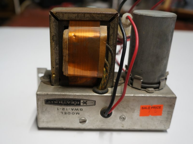
The GWA-12-1 vibrator unit is designed
to be screwed to the back of the transceiver, and is positioned so the
plug and socket are in the correct position. In the case of the GW-12A,
an 11 pin plug and socket is used. This differs from the ordinary octal
type used on some other sets.
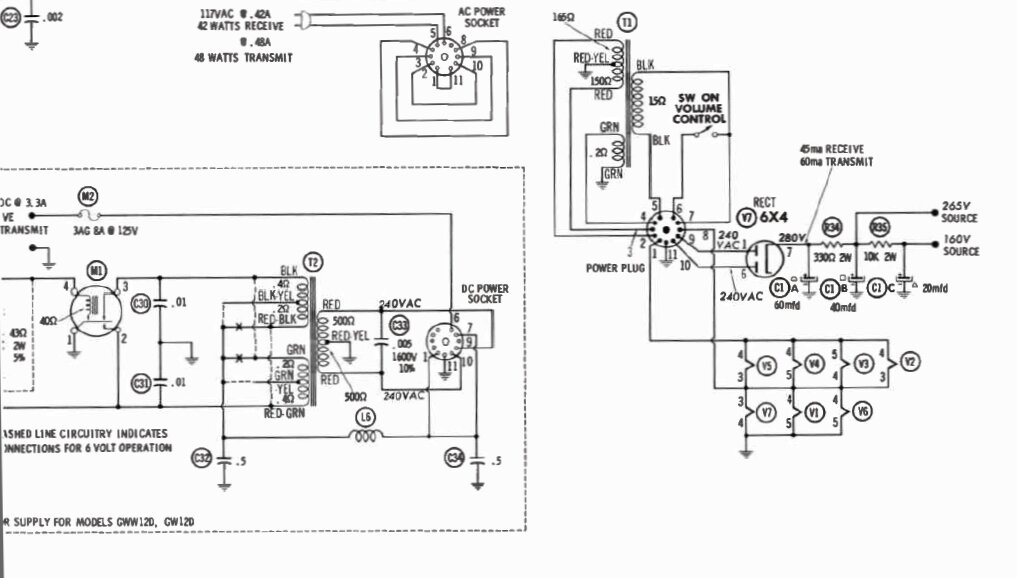
The Circuit.
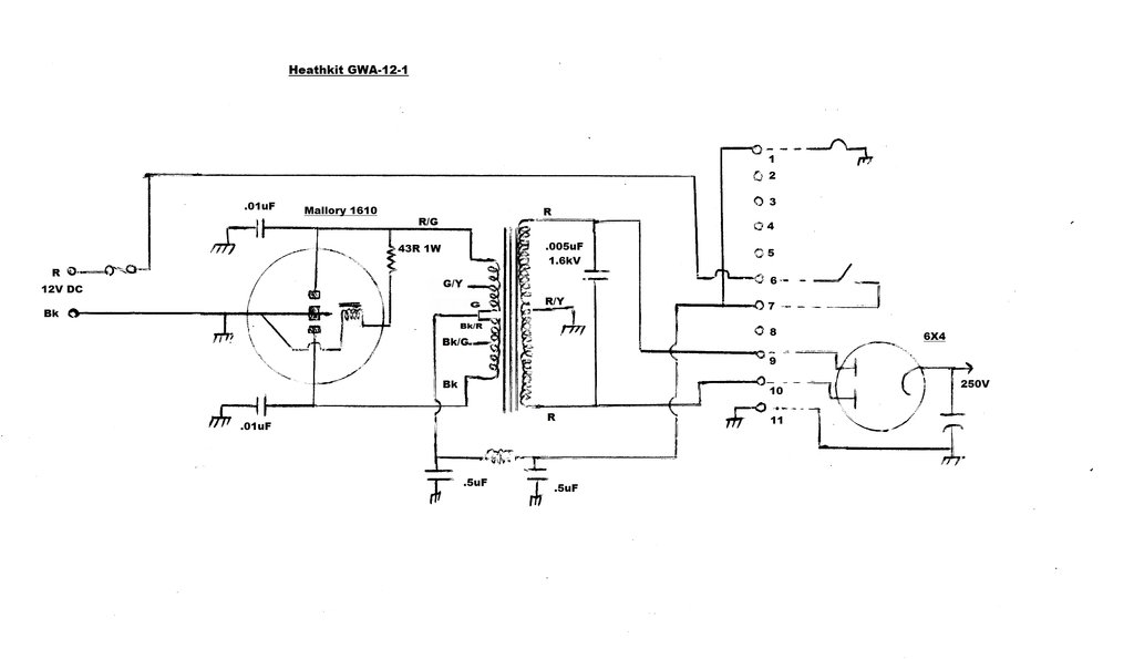
Circuit of the GWA-12-1. Components to the right of the 11 pin plug
and socket are in the GW-12A.
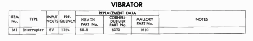
The design is completely standard, using
a Mallory 1610 non-synchronous vibrator, driving a transformer with centre-tapped
secondary for subsequent rectification with a 6X4 valve. The 1610 is a
6V shunt drive vibrator, but has the drive coil connected to the otherwise
unused pin. By linking this pin to the "pull" contact, it works exactly
like any other shunt drive vibrator; i.e., when the "pull" contacts make,
the drive coil is short circuited, causing the reed the swing back to the
"inertia" contact. And, the process repeats while ever power is applied.
However, if a 43R resistor is connected
in series with the drive coil, the vibrator can be operated from 12V. The
convenience of course, is that only one type of vibrator is required for
both 6 and 12V.
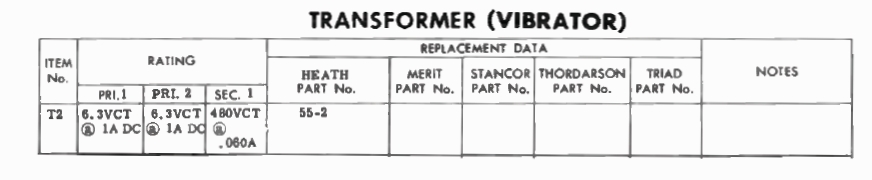
Similarly, by providing the transformer
with a tapped primary winding, both 6 and 12V operation can be accommodated.
This scheme has been described also in
the Heathkit
GP-11 power supply article.
The Heathkit VP-1-6 and VP-1-12 power
supplies also allow 6 or 12V operation, and in fact the GWA-12-1 uses what
appears to be virtually the same transformer. Unlike the GP-11, the transformers
for these latter models have two separate tapped primary windings. For
12V they are connected as a single centre-tapped primary, as shown above.
For 6V operation, the windings are connected in parallel (in phase), and
the hitherto unused tappings become the 6V feed point. Of course, the 43R
resistor also needs to be shorted out.
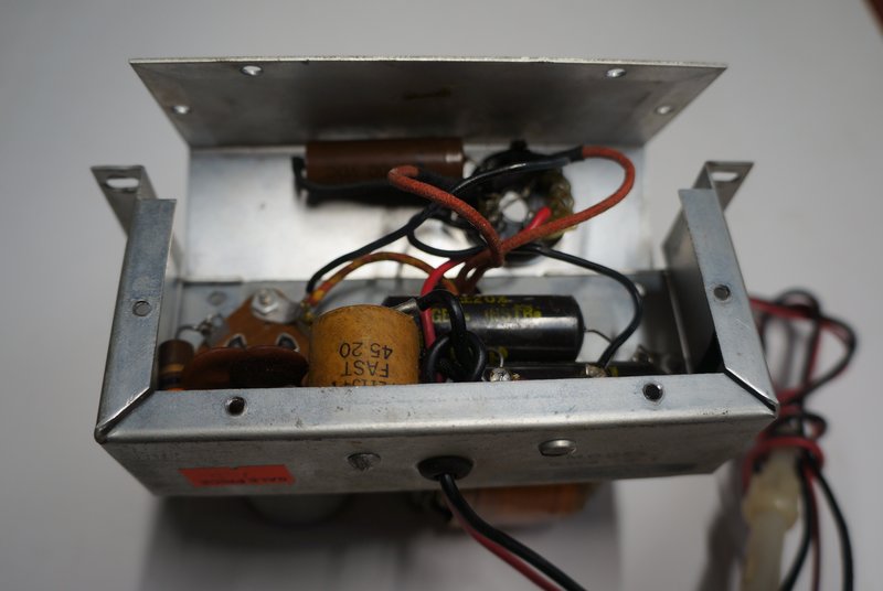
RF filtering is achieved with the 0.01uF
ceramic capacitors across the vibrator contacts, as well as the pi filter
in the supply line, consisting of a choke and two 0.5uF capacitors.
The timing capacitor is a 0.005uF 1600V
across the full secondary. There is no damping resistor as per the VP-1-6
and VP-1-12.
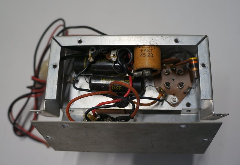
Vibrator socket and 43R resistor are at right.
Unlike the GP-11, the GWA-12-1 uses the
more conventional method of vibrator connection. That is, the transformer
centre-tap is fed with 12V and the vibrator reed is earthed, rather than
the other way round. Electrically, the two methods work identically.
Output of the GWA-12-1 is around 260V
at 60mA. Rectification is achieved by the 6X4 inside the CB set. There
is a 117V power transformer permanently mounted inside the set, and depending
on the links in the 11 pin plug, either the AC transformer or the vibrator
transformer secondary is connected to the 6X4 plates. Since the vibrator
is a non-synchronous type, input polarity is not important. The black wire
is connected to the vehicle chassis, and the red to the battery supply,
regardless of whether this is positive or negative.
Timing capacitor is mounted on the output socket.
The on/off switch is connected between pins 6 and 7, so that on 117V it interrupts the supply to the power transformer primary, but when the GWA-12-1 is fitted, it instead switches the DC input. The valve heaters are also connected to the switch in this mode, by the link between pin 1 and 7. It is not known how the heater circuit in the transceiver is wired, and whether 6 or 12V operation is selected by links in the 11 pin plug. Ordinary 6.3V valves are used, which would be connected in series-parallel for 12V, and all in parallel for 6V.
The unit I have was wired for 12V. Seeing
the vibrator was a Mallory, I wasn't surprised at the ease of getting it
started after many years of disuse. The vibrator waveform was as expected.
Since the timing capacitor is the original paper type, it should be replaced
if this power supply is put into regular use.
I can't ever imagine acquiring the GW-12A
CB radio, but the power supply could obviously be used for other applications.
The 11 pin plug and socket is standard. However, if the power supply was
connected to a receiver via a length of cable, there is the risk of RFI
being radiated from the two active secondary leads.
From the Sams Photfact CB Radio Series CB-5 March 1964.(Available
at www.worldradiohistory.com)