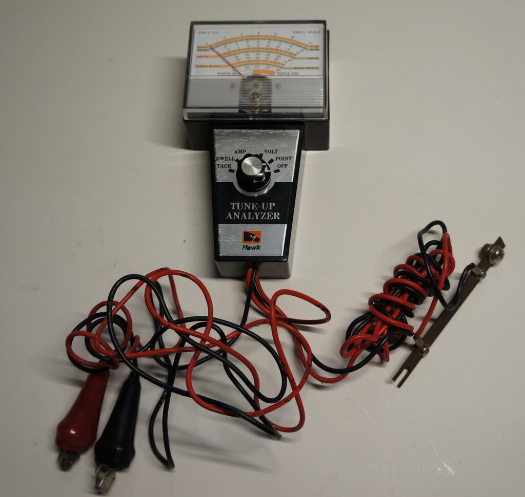
Note the current shunt to the right.
Note the current shunt to the right.
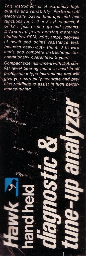
This Hawk 743 Tune Up Analyzer came to me along with some other instruments, one of which was the Hawk 620 Exhaust Gas Analyzer. And like that instrument, until now, it was not something I ever needed since the Hilux has electronic ignition, and the Model T ignition system is not really compatible. However, with the advent of the Jeep, I certainly could use it, especially as it's 6V compatible. It looked like it had never been used, still in its box. The wires were still bundled up with that 'never been used before' appearance, and with the styrofoam melting around them.
Functions.
The 743 provides several functions:
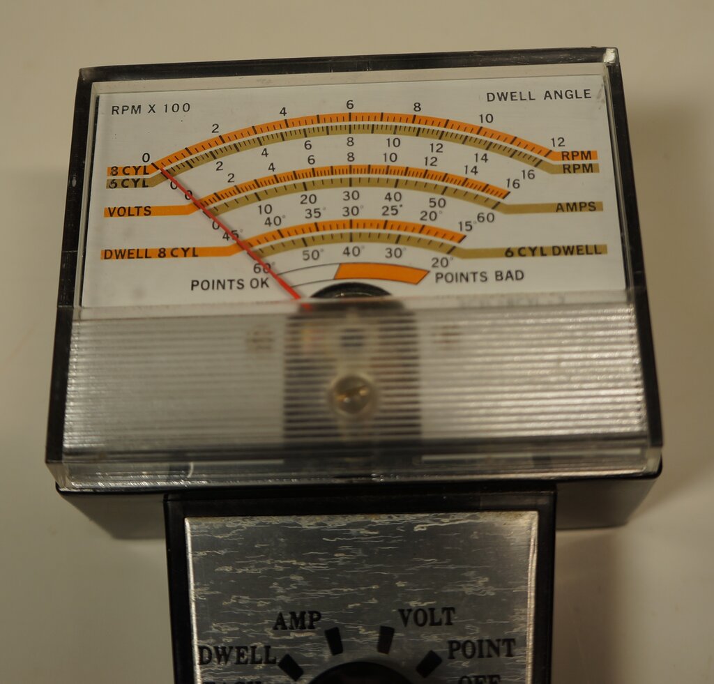
Close up of the scale reveals the testing abilities of the 743.
Looking at the meter scale, we can see
the top scale is for the tachometer, which is calibrated for up to 1200
rpm for 8 cylinder engines, or 1600 rpm for 6 cylinders. The intentions
this was made for the U.S. market are obvious - there's no 4 cylinder scale!
However, a note is given to say that the
8 cylinder readings are doubled for 4 cylinders.
The voltmeter accomodates 6 and 12V systems, being calibrated from 0 to 16V. The ammeter reads 0 to 60A.
Dwell readings are again for 8 and 6 cylinder engines, reading from 15 to 45 degrees, and 20 to 60 degrees respectively. Again, the 8 cylinder reading is doubled when measuring a 4 cylinder engine. In this case, it will read 30 to 90 degrees.
Finally, there is a points test scale. This is uncalibrated and simply indicates if the points are good or bad.
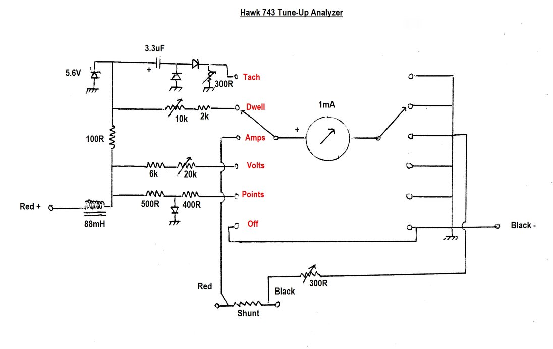
The design is a very simple one, with
no transistors or IC's. Considering that just about every other tacho and
dwell meter I've seen circuits of, have active components, suspicion fell
on how accurate this instrument would actually be. As expected, and as
it turned out, it is not really a precision instrument.
Tachometer.
The red and black leads are connected
across the points, with the black lead being negative (earth in a negative
earth vehicle). The largely square wave waveform is fed through the choke
and 100 ohm resistor. The 5.6V zener diode clips the peak to peak voltage
of the waveform to 5.6V, regardless of whether the supply is 6 or 12V.
The reactance of the capacitor varies with frequency, so the greater the
frequency, the more current flows through the rectifier circuit consisting
of the two diodes. The current then flows into the meter, which is shunted
by the 300 ohm preset for calibration. The value of the capacitor is chosen
to be such that it differentiates the waveform. This is so the rectifier
input sees a narrow pulse of current. Provided that the duty cycle of the
waveform is greater than this pulse, the meter will respond only to the
frequency, and not the duty cycle (dwell).
The choke suppresses the high voltage
spike present when the points open. For the Jeep, this was measured at
around 240V.
Dwell.
The same 5.6V peak to peak supply is shared
by the dwell function. In this instance, the frequency is not important,
and there are no frequency dependent components. Here, the meter will read
the average current, which is dependent on the duty cycle. The longer the
voltage is positive over the full cycle, the greater the average current.
The 10k preset provides calibration. Again, the 5.6V zener ensures the
reading is not affected by input voltage variations.
Amps.
This is a basic ammeter circuit, with
the 1mA meter movement fed from a low resistance shunt, made from a piece
of brass. The 300 ohm preset provides calibration adjustment.
Volts.
Again, this part of the circuit is completely
straight forward, with the meter movement fed from the supply voltage via
the 6k and 20k resistors. These act as a multiplier, with the 20k providing
calibration. The input voltage here is of course not clipped
by the 5.6V zener, and is the full battery voltage.
Points.
This also functions as a simple voltmeter,
albeit uncalibrated. However, instead of the full battery voltage, this
is used to measure the voltage across the points when closed. With the
ignition switched on and the engine not running, a small
voltage will be developed across the points, because of their resistance
and the current flowing through the ignition coil. Obviously, the cleaner
the points, the better the contacts between the two surfaces, and the lower
the voltage across them.
The diode limits the voltage to around
700mV, should the meter be switched to this position with the points open,
and the ignition switched on. However, if connected with incorrect polarity,
there will be no voltage limiting, and possibility of meter damage. What
is perhaps surprising is the absence of the usual back to back diodes wired
across the meter.
Off.
In this position, the meter is shorted
out for protection. Sudden movement, such as might occur when carrying
the instrument, can cause the meter needle to move violently, and in extreme
cases, damage the movement. By shorting it out, the voltage generated in
the coil as it moves creates a drag, severely damping the movement. This
is a common circuit seen in all good multimeters.
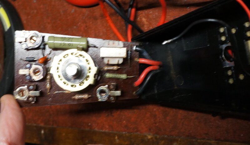
Component side of the PCB.
Apart from the dwell and tacho, all the other functions can be tested with a variable power supply.
Volts.
Given the low cost meter movement, I wasn't
really surprised to see inaccuracy for the voltage measurement. One would
assume that simply calibrating the meter for full scale (16V) is all that's
required. Provided the meter is accurate, lower voltages will be indicated
correctly on the scale, all the way down to 0 V.
In this instance, calibrating the meter
this way resulted in lower voltages reading too low. The problem was meter
non linearity. If I calibrated the meter at 6V, it would read too high
at 12V. Possibly the meter magnet has weakened over time, which is one
cause of this. I ended up calibrating it for 9V; being mid way between
the two voltages it would be used to measure; i.e., 6 and 12V. With 6V
input , the meter now reads 6.5V. The error is tolerable, but this is certainly
not a precision instrument. It should not be used to set a voltage regulator,
for example, but is perfectly fine for ordinary fault finding. In retrospect,
calibrating it for 6V would be better, since it's not likely to ever be
used with anything besides the Jeep.
Amps.
Using 2A and 8A for testing, this actually
turned out to be very accurate. There was no need to re-calibrate.
Points.
Half scale reading was at 500mV. Full
scale was 1.23V. Both these figures are what I would expect.
Tachometer.
Here's where things start to get complicated.
Assuming the tacho circuit is not voltage sensitive (provided the input
voltage is greater than 5.6V), it should be possible to use a square wave
function generator to test this.
To convert rpm to frequency for a 4 cylinder
four stroke engine, simply divide the rpm by 30. For example, 1500 rpm
is 50 Hz.
In this instance, 37Hz resulted in a reading
of 600 rpm on the 8 cylinder scale. This is equivalent to 1200 rpm for
4 cylinders. The meter was reading slightly high - it should have been
555 rpm. In the scheme of things, the difference is certainly not super
critical, and at this stage did not feel the need to re-calibrate it. Interestingly,
reducing the voltage below 11V p-p dropped the reading. It would appear
the input choke might have been affecting this, since with the function
generator there is no high voltage spike.
To clear up any possible errors by using
a function generator, the analyser was then connected to the Jeep. The
results were the same.
A CRO was connected for verification,
and measured 28.6 Hz at idle speed. This equates to 858 rpm. The meter
was showing just over 400 rpm on the 8 cylinder scale (800 rpm 4 cyl.).
Close enough not to worry about.
Dwell.
Things became even more complicated trying
to test the dwell with the function generator. The readings were unacceptably
inaccurate.
But first, what are we looking at?
Dwell is the duty cycle of the points
- how long they are switched on for, relative to the rotation of the distributor.
Since the rotation of the distributor is 360 degrees, it follows that for
a 4 cylinder engine, the maximum dwell possible is 90 degrees. (8 cylinders
is 45 degrees, and so on).
In the case of the Jeep, the dwell angle
is specified as 47 degrees. To convert that into a duty cycle percentage,
simply divide 47 into 90, and multiply by 100. The result is 52%.
Testing with the function generator at
a 50% duty cycle gave an erroneous result; 30 degrees on the 8 cylinder
scale (equal to 60 degrees for 4 cylinders). And here is the problem of
using such a simple circuit. It is dependent on the wave shape and amplitude.
When connected to the Jeep, the result
was far better, with a 44 degree reading. Not far off the specified 47
degrees, but was it really 44 degrees?
The CRO was connected to actually measure the waveform:
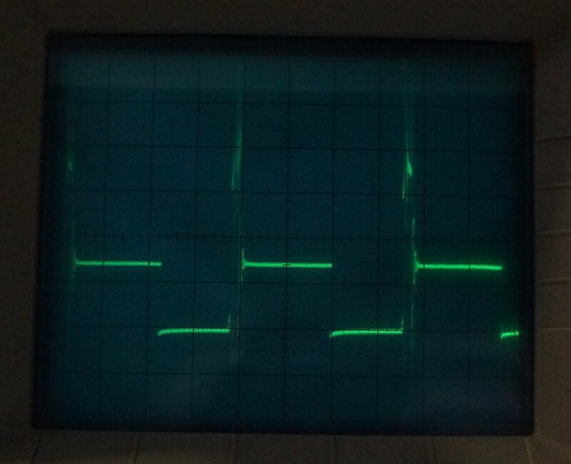
CRO waveform across the points at idle speed. The short peaks are
about 240V, while the longer peaks are 7.4V.
At idle speed, the period of the waveform was 32.6 ms. The contacts were closed for 14.5 ms. The duty cycle is thus 0.44. Converted to degrees, this is 0.44 x 90 = 40 degrees. However, the meter was showing 22 degrees on the 8 cylinder scale (44 degrees for 4 cylinders). A very slight tweak of the calibration brought that back to 20 degrees (40 degrees for 4 cylinders). Importantly, the dwell angle did not change with engine revs. This indicates correct operation, because it is only the duty cycle we want to see here.
Since the Jeep runs so well at high speed, I did not attempt to increase the dwell. A greater amount of dwell than specified would be less desirable because of higher points current, etc.
Surprisingly, there is very little information
on the internet about calibrating dwell meters. A lot of articles seemed
to be variants of the same AI regurgitation, which didn't actually tell
you anything.
With the analyser tested and deemed satisfactory,
I ordered another Pelican case knock-off, as with the exhaust gas
analyser. The was enough room for the Colortune (transparent spark plug),
and a Hawk neon timing light.
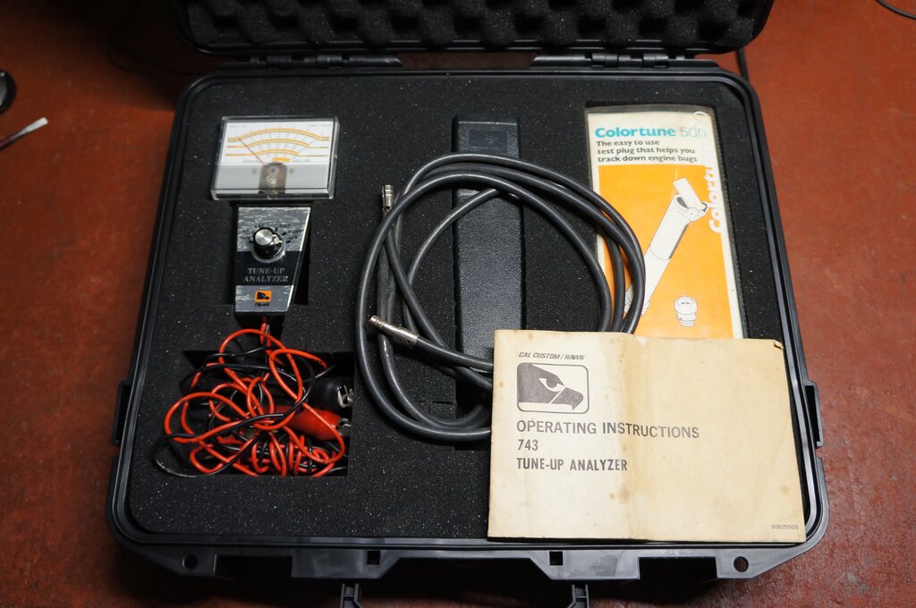
Safely stored in a Pelican case with other ignition testing accessories.
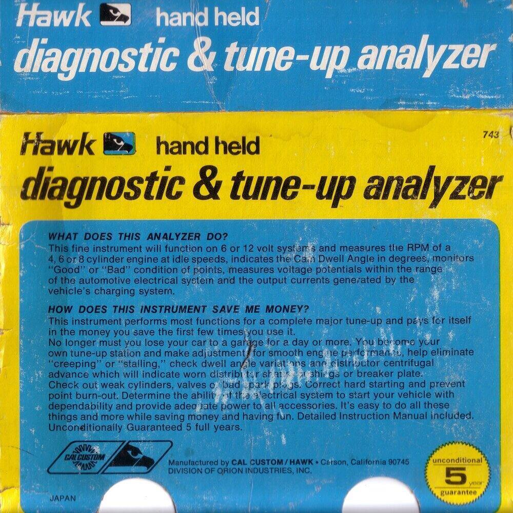
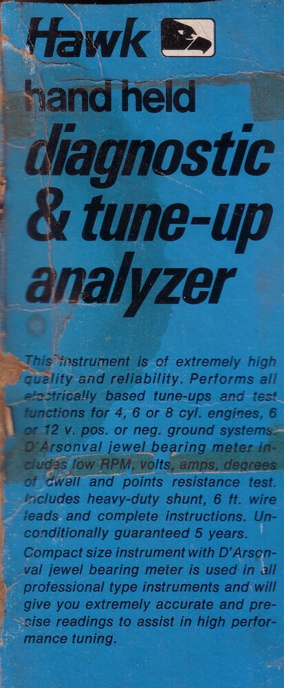
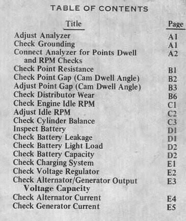
The supplied manual is quite comprehensive in describing the various tests which go beyond the basic functions.
For my own example of the analyser, in the condition as I found it, it would have been OK for fault finding. The dwell and tach were close enough to actually set up the idle and dwell, but the voltmeter was not suitable for setting up a voltage regulator.