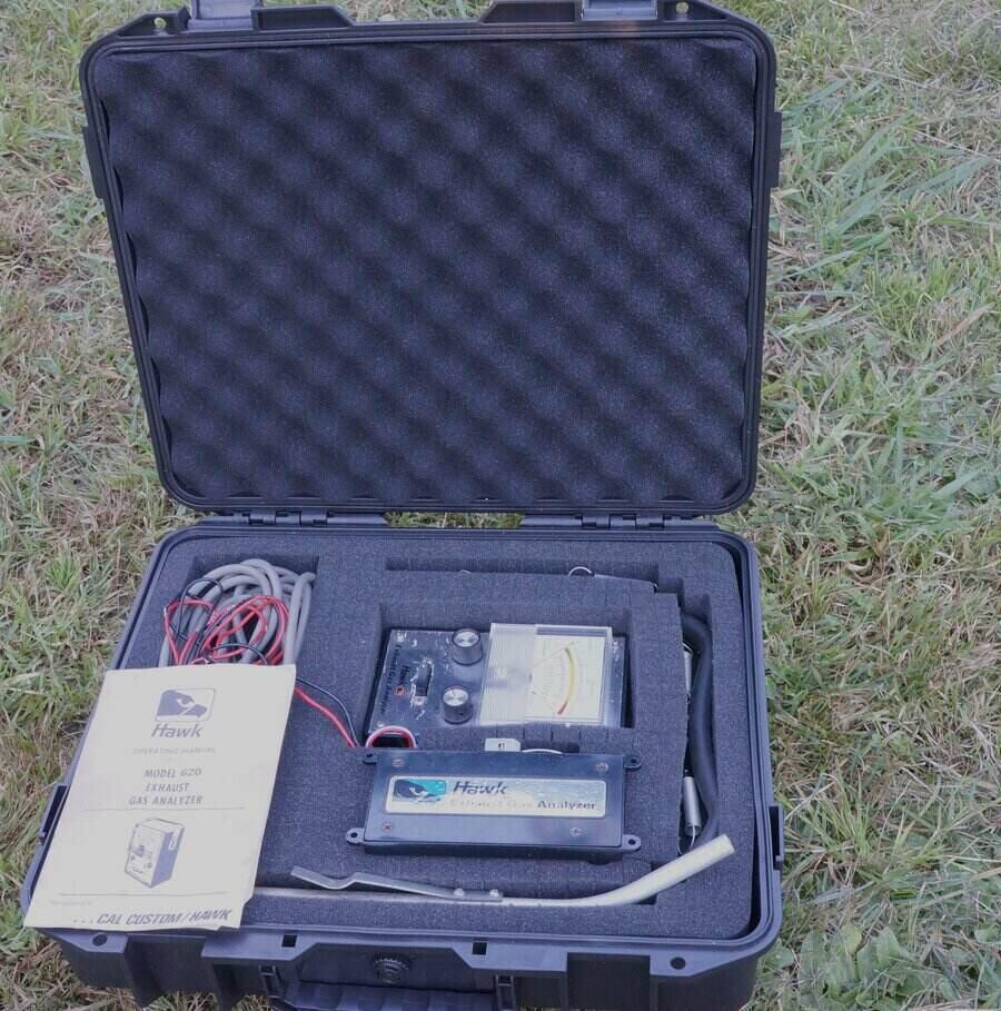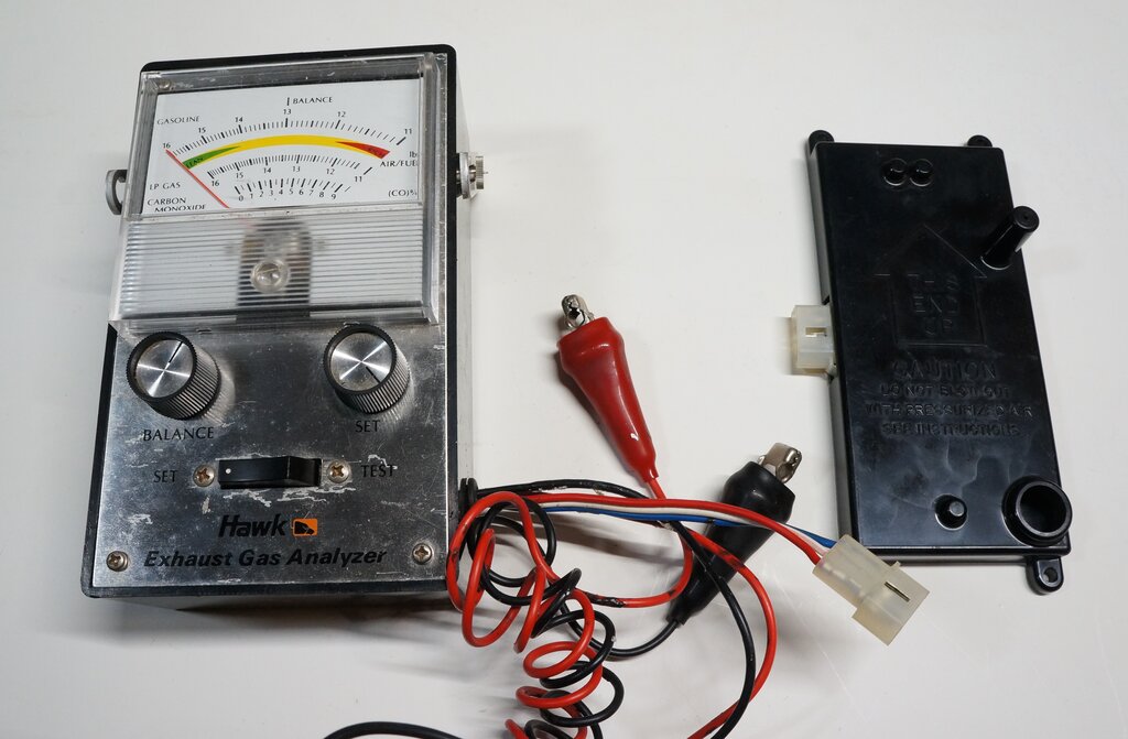
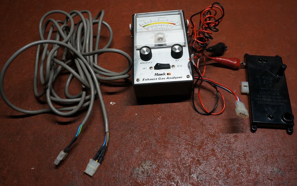
Exhaust gas analyser with sensor unit.
Exhaust gas analyser with sensor unit.
I had been given some automotive tune up
instruments some years ago, and I'd forgotten this unit was among them.
That is, until I was looking through the shelves in my garage for something
else. I hadn't ever needed it before, since I've not had to do any carburettor
adjustments on the Hilux, and the Model T is so simple to adjust, that
such sophistication isn't needed.
But now that I have a Jeep, and I was
curious about the carburettor adjustment, this was a welcome find. This
is especially because the Stromberg carburettor fitted is not the original
type, so the Jeep manual is not relevant to its adjustment. Importantly,
I wanted to see that the fuel mixture was not too lean. The kit of accessories
for the tester was complete, except for the cable which runs between the
sensor and the meter. I simply used clip leads to connect the two, to verify
its operation, before making a new cable.
These EGA's, along with tacho/dwell meters, vacuum gauges, and timing lights, were once part of the home mechanic's tool kit. Indeed, the box in which this instrument came is labelled as 'The Sunday Mechanic'. This all started to end around the mid 1990's, with fuel injected and computerised cars becoming the norm. Now it's only vintage car enthusiasts using this equipment. The Hawk 620 appears to be of 1970's design, and is made in Japan, or at least assembled from Japanese components. It's built into a plastic case of the type popular for electronic projects, known locally as a 'Jiffy box' or 'Zippy box'. The only elaboration is the aluminium handle.

"The Sunday Mechanic by Hawk".
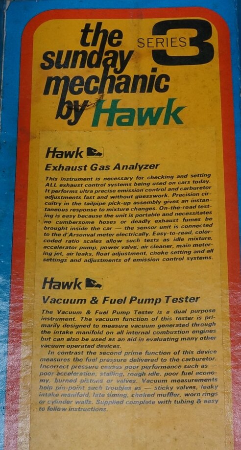
Kit also contains a vacuum gauge.
Surprisingly, there was virtually nothing on the internet about this instrument, except a few for sale ads. Some brief forum posts mentioned things like 'Wheatstone bridge' and 'thermal conductivity', but that was about it. I also noted a few requests for instructions. Since I like to understand the instruments I use, it was obviously necessary to reverse engineer this EGA, and so to the rest of this article:
Principle of Operation.
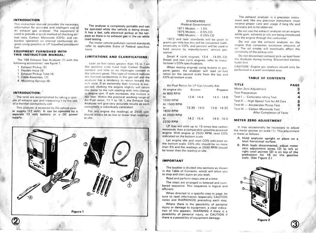
A rubber tube attaches to the sensor,
with the other end inserted into the exhaust pipe using a clip on attachment.
A portion of exhaust gas thus flows through the sensor. The sensor connects
to the meter unit, which in turn connects to a 12V battery via clips.
Electrically, the instrument is very simple,
being essentially a Wheatstone bridge. There are no active components.
The sensor unit operates as a thermal conductivity cell. Gas to be analysed
flows over a hot wire, and the resistance changes depending on the hydrogen
content. The air/fuel ratio is extrapolated from this.
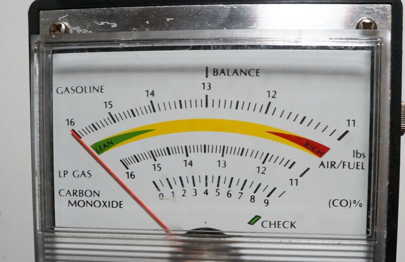
Meter scale shows air to fuel ratio, in the range of 16:1 to 11:1.
Thermal Conductivity Cell.
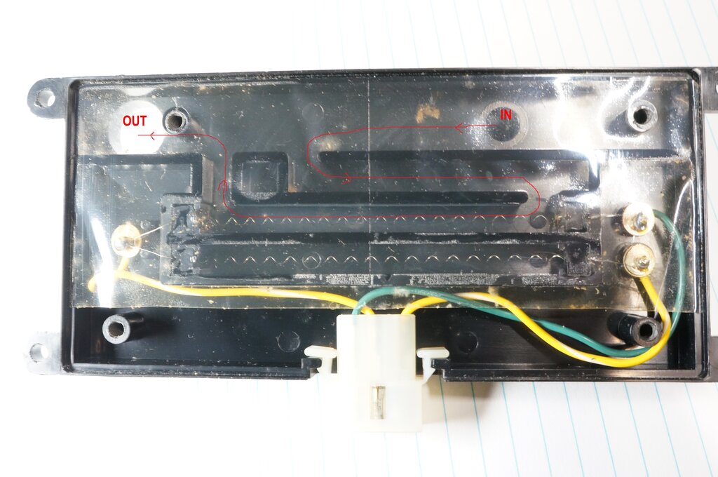
Inside the sensor unit. Red line shows path of exhaust gas through
the test cell. Bottom chamber is the reference cell.
So that the instrument can be made accurate
with repeatable results, two thermal conductivity cells are used. As can
be seen in the above photo, the cells are identical, with the same length
of resistance wire. As such, their resistances are also identical.
When connected to a bridge circuit, the
output of both would cancel, resulting in no output voltage. However, it
can be seen that one of the cells is closed off from the gas flow, while
the other is in its path. The closed off cell is the reference, so the
output is the difference between the reference cell and the testing
cell. Such things as ambient temperature do not therefore affect calibration,
since both cell resistances will track by the same amount.
Circuit.
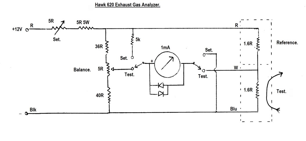
Circuit of the analyser. Note the simplicity of the bridge circuit.
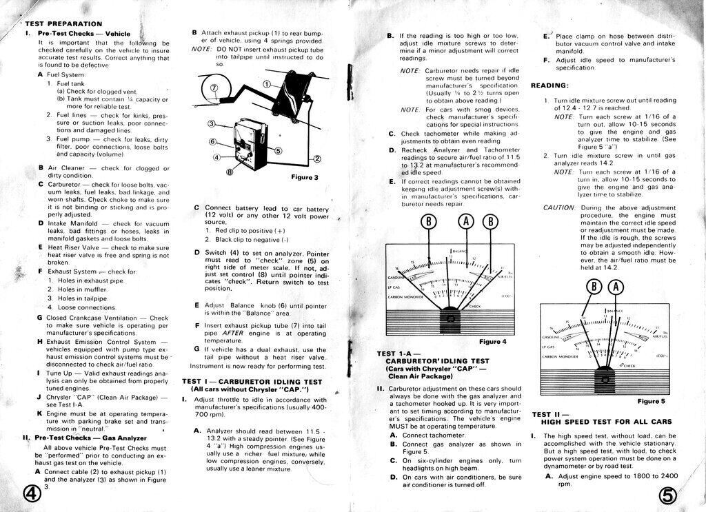
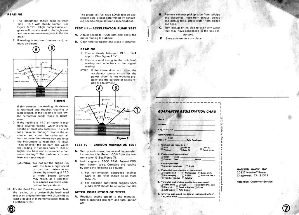
The Set rheostat is adjusted so that with
the switch in the Set position, the meter reads just on full scale deflection
('Check' mark on the scale). This operation sets the bridge supply voltage
for correct calibration. In this instance, it was measured at 5.14V.
The meter is a 1mA type, and in series
with the 5k resistor, full scale deflection will be achieved at this voltage.
The 5.14V feeds two voltage dividers. One is the adjusting arm of the bridge, which consists of a 36 and 40 ohm resistor, and a 5 ohm potentiometer at the mid point. From this, we can see that the mid point adjustment of the potentiometer will provide slightly more than half the supply voltage. With a 5.14V supply, the divider current will be 5.14 / 81 ohms = 63.5mA. With the potentiometer set to mid point (2.5 ohms), the voltage at its wiper will be 63.5mA x 42.5 ohms = 2.7V.
The second voltage divider is, of course, the two resistance wires in the sensor unit. Their cold resistance is 1.6 ohms each, which would normally draw 5.14 / 3.2 = 1.6A. However, the heating of the sensor wires causes their resistance to increase, and the current drops to about 750mA. Now the resistance has increased to 5.14 / 0.75 = 6.9 ohms, or 3.4 ohms each. The important thing to note is that the voltage at the mid point will still be half the supply, regardless of what the resistances actually are, since both are the same. We should have 2.57V here.
With the switch in the Test position, the
meter is now connected across the two arms of the bridge. Since there will
be 2.7 - 2.57V = 130mV across the meter, it will show deflection. The 5
ohm Balance pot is then adjusted so this deflection is mid scale, at the
'Balance' mark.
This is why the resistors in the adjusting
voltage divider are not exactly equal - we need the meter to show this
slight initial offset.
Next, gas is fed through the test cell. If its resistance drops, the meter will move towards the right (i.e. rich mixture). If the resistance increases, the meter will move to the left and show a lean mixture.
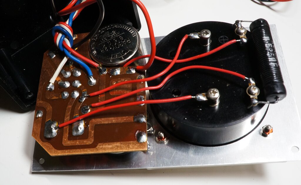
There's not a lot in it! The top terminals on the meter are not
connected to anything inside the meter. They are merely for supporting
the resistor.
Meter protection is provided in the usual way with back to back silicon diodes. These limit the maximum meter voltage to about 700mV, should any incorrect operating conditions occur (e.g., one of the sensor wires being open circuit).
Supply Voltage.
The Hawk 620 is designed for 12V operation.
It will operate from 9 to 12.9V within the range of the Set control. Since
there are no active components or electrolytic capacitors, no reverse polarity
protection is needed. Reverse polarity will simply result in negative deflection
of the meter, and the inability to set the Check mark.
Given that the bridge supply is approximately
5V, it would appear possible to make this instrument work from 6V. This
would simply entail shorting out the 5 ohm 5W resistor in series with the
Set rheostat. Indeed, this worked, but the Set rheostat was almost right
at the end of adjustment. With a fully charged 6V battery it could be used
this way, but I'm loath to modify commercially made equipment, and for
the infrequent use this instrument will get, obtaining 12V is really not
difficult. Since the current draw is about 750mA, a small SLA battery is
quite adequate.

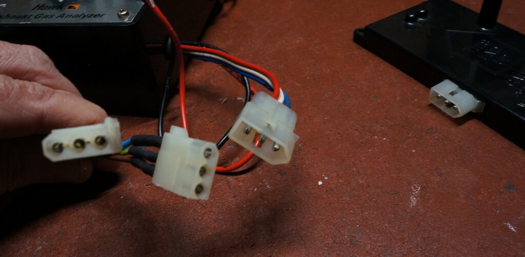
Modified 4 pin Molex plug fits nicely.
Next was the cable. I spent some time trying to find something suitable. Separate wires are always messy, especially for the length required. Flat three conductor power cord was never used in Australia. Multi core audio type cables were too fragile, and given the low resistance required, I felt the conductor cross sectional area might not be enough. In the end, I used 0.75mm three core flex as used for 240V appliances. Anything thicker than 0.75mm would be too bulky and difficult to fold up for storage.
Three core mains cable solved the problem of what cable to use.
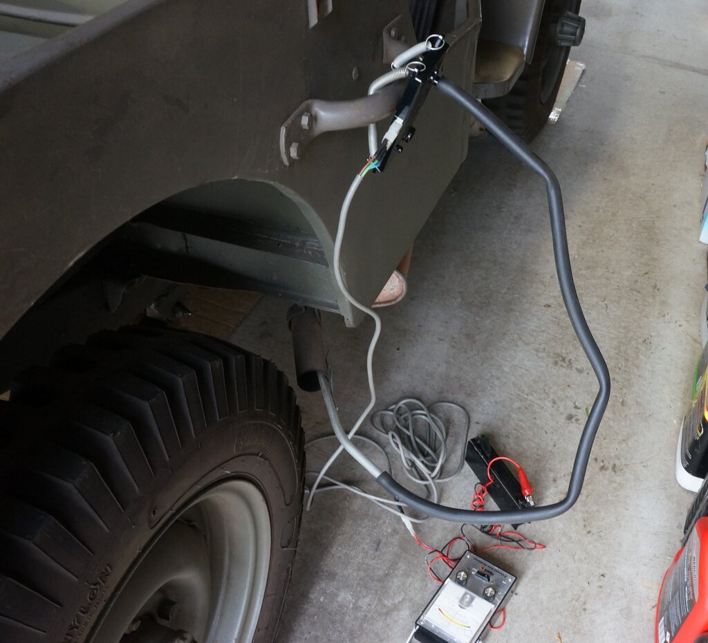
Sensing tube is inserted to exhaust pipe. Springs secure sensor.
Since the Jeep's exhaust is at the side, I used the handle to attach the sensor:
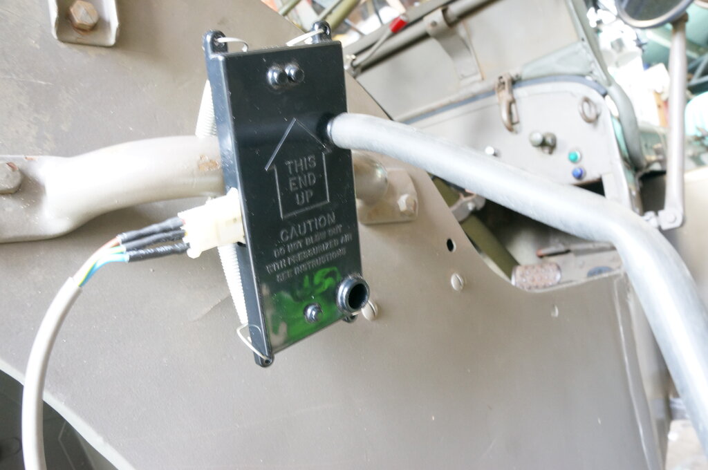
Sensor is mounted vertically in the direction shown.
It is important that the sensor is mounted with the indicating arrow up. The gas flows in from the top and out the bottom, ensuring the test cell is filled. The sensor is also sensitive to position, and if moved after the Set and Balance controls are adjusted, the reading will change. This is particularly obvious changing it from vertical to horizontal. Presumably, this is an effect of the warm air escaping from the test chamber faster than when horizontal.
Because the resistance wire in the sensor cells changes its resistance as it warms up, the instrument must be given a few minutes to stabilise after powering up. After a few minutes, check the Set and Balance settings, just before taking the reading.
Of course, the engine must be brought up to normal temperature before the analyser is set up. The important thing here is not to insert the probe into the exhaust pipe until the reading is ready to be taken. It is surprisingly sensitive, and any trace of exhaust gases prior to this will affect the initial calibration of the Set and Balance controls.
In summary, the operation is as follows: