This unusual set was acquired from an HRSA
meeting. The seller knew I liked live chassis sets and drew my attention
to it. When I saw it was also a three valve regenerative set, I had to
have it. There were some notes supplied with it; someone having attempted
to trace out the circuit. As I discovered later, there were a few mistakes.
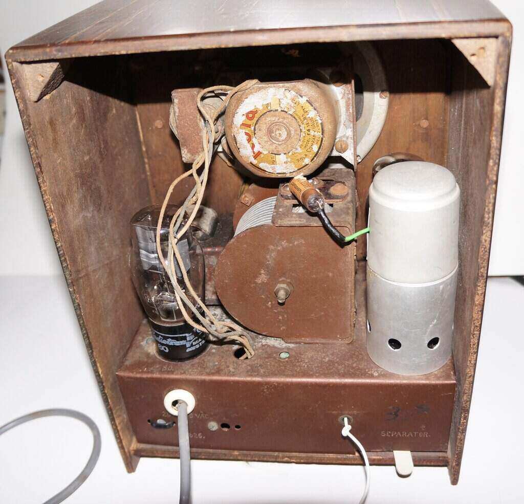
Rear view gives an idea of size. Note the Separator control.
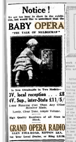
Newspaper advertisement from 1934.
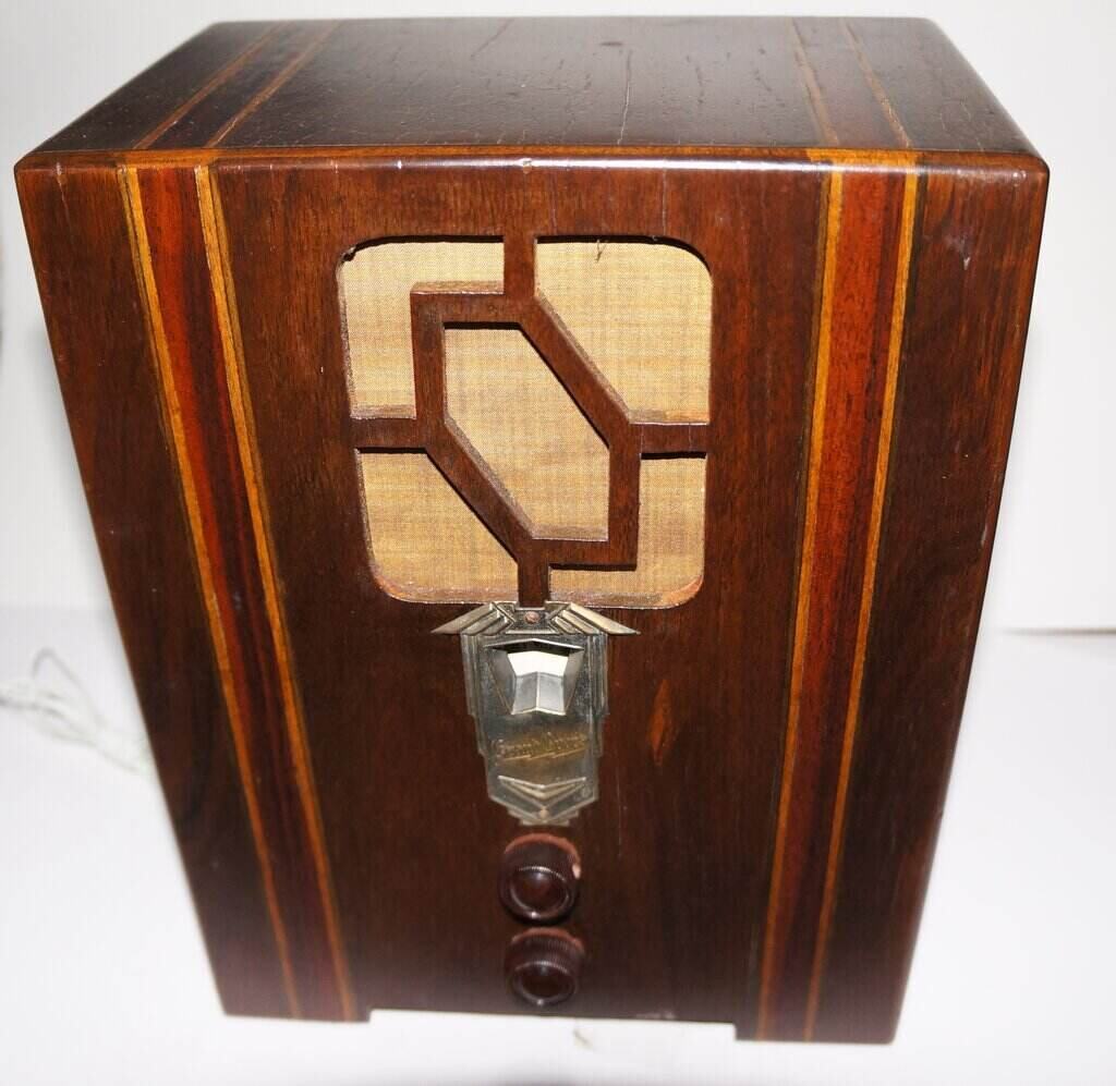
Grand Opera is a brand I had never heard of before. A Trove search revealed that it was a Melbourne based manufacturer. This particular set turned out to be a 1934 model for "local reception". In other words, a low gain set.
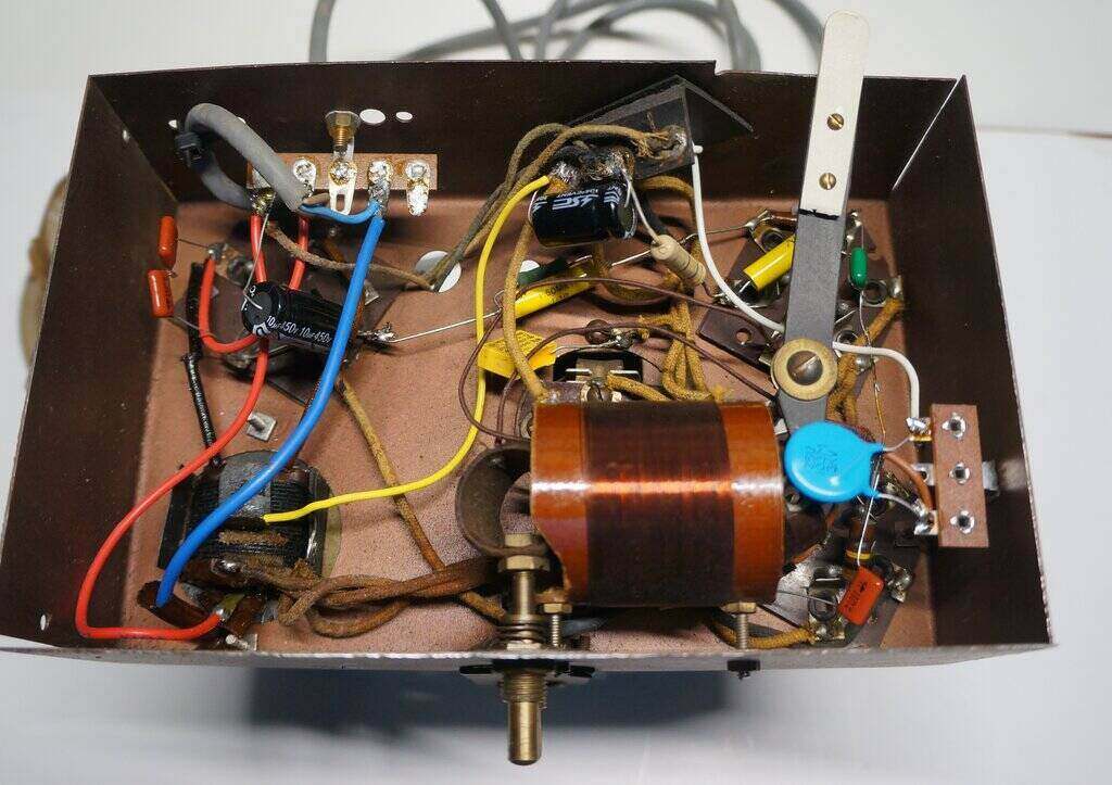
Under chassis view. Note the variable coil coupling for the regeneration
control.
One interesting aspect of the design was
the volume control. I had expected the usual variable capacitor to adjust
regeneration, and function as a defacto volume control. Instead, it used
a variometer control; that is, the regeneration coil was physically adjusted
relative to the tuned circuit. The "Separator" control was similarly designed,
but adjusted by a lever at the rear of the cabinet. It adjusts the degree
of aerial coupling.
The set had been 'restored', and looking
under the chassis showed a number of non original features. Two modern
tagstrips had been fitted. One curious aspect is the filter capacitors.
For an Australian made set in the 1930's, wet electrolytics would normally
be used. However, there was nowhere on the chassis they could have
been mounted. I can only assume that imported dry electrolytics had been
used.
The notes supplied showed that the restorer
had added an aerial isolation capacitor, and that the chassis was
live. Yet, there was no evidence that a back had ever been fitted to the
cabinet.
Time to trace out the circuit and see
what the true story was.
There were two hand drawn circuits supplied; both being slightly different, and containing obvious errors. Furthermore, there were a few problems with the 'restoration', although the set appeared to work normally.
Circuit Operation.
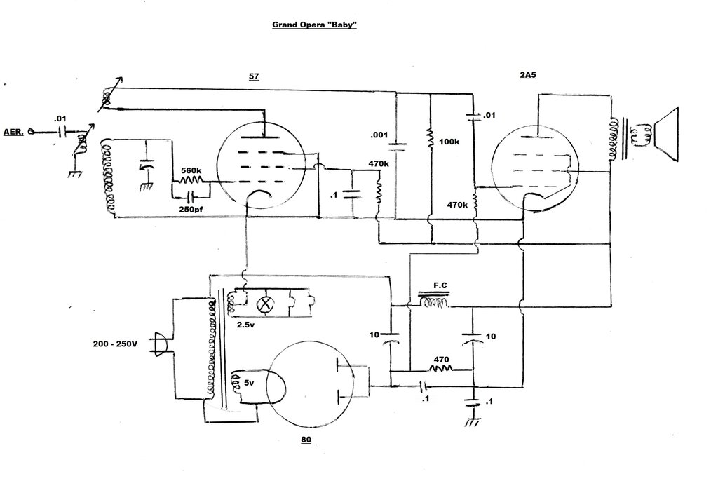
A regenerative grid leak detector based
around a 57 pentode feeds a 2A5 pentode audio output stage. The 240V mains
is rectified by an 80 rectifier to provide the B+.
Incoming signal from the aerial passes
through an isolating capacitor into the aerial coil primary winding. By
means of the "Separator" control, the degree of aerial coupling can be
adjusted in a physical manner. In situations where the set is operated
close to the transmitters, the selectivity of the regenerative detector
may be inadequate, and this can be improved by reducing the aerial coupling.
Of course, gain drops off by doing this, but in a strong signal area this
is not likely to matter.
The notes indicated that the aerial isolation
capacitor had been added by the restorer. It was a .022uF 100V. Totally
inadequate for 240V mains! The immediate question now was why had this
capacitor been added - why would the set have been made without it? As
will be revealed later, the mains wasn't meant to be connected directly
to the chassis, as our restorer had thought.
The detector circuit is perfectly standard, with the grid leak consisting of a 250pF and 560k. No doubt, the original resistor would have been 500k; the set being made prior to preferred values. There are no separate volume and regeneration controls. This means volume is adjusted by the regeneration control only. The limitation of this is that reducing volume also reduces selectivity. The ideal design of a regenerative set allows for maximum regeneration (before oscillation), and thus greatest selectivity, with the volume adjusted by a separate control. In most circuits of this type, the amount of positive feedback is adjusted by a variable capacitor in series with the regeneration winding, or by adjusting the screen or plate voltage of the detector with a potentiometer. With this set, however, the coil is physically adjusted in terms of its distance from the aerial coil.
The detected audio appears at the 57 plate, which is bypassed with .001uF. Plate load is 100k. The audio then proceeds to the 2A5 output pentode via the .01uF coupling capacitor. The 2A5 circuit is standard, feeding a Rola 4F electrodynamic speaker. Back bias is used for the 2A5, and feeds the grid via a 470k resistor (presumably 500k originally).
Power Supply.
Apart from the variometer type regeneration
and aerial coupling controls, the power supply is the other unusual aspect
of design. As I was beginning to suspect, it wasn't actually a true live
chassis set, in that the mains wasn't directly connected to the chassis
at all. Rather, a floating 'earth' was used, which was then bypassed to
the chassis by means of a capacitor, whose value is low enough to prevent
a shock hazard. Indeed, this turned out to be true. It would explain why
the set didn't originally have an aerial isolating capacitor, since with
the chassis isolated, it didn't really need one. However, for safety, I
did retain the capacitor, but changed it to a .01uF 3kV type.
I found the chassis isolation capacitor
all right - it was .0068uF 100V. Not only was the voltage rating far too
low, but it had been bridged out with a piece of wire! Our would be restorer
had in fact made the set quite unsafe, when the original design would not
have been.
Obviously the wire had to be removed,
and when I did so, noticed strong modulation hum. No doubt the restorer
found that bridging the capacitor stopped the hum - which it did most effectively.
The .0068uF bypassing was not sufficient, and with such a low value I wasn't
surprised. I found that .1uF was a good compromise between removing the
hum and not causing a lethal shock, and I suspect this is what the original
would have been. Given the reactance of a .1uF capacitor at 50c/s, a maximum
of 7mA can flow. It's higher than one would like, (one reason I retained
the aerial isolator) but it does show up a potential limitation of this
type of power supply. The alternative is to connect the chassis directly
to the negative, but the cabinet would then require a back to prevent any
contact.
The valve heaters are supplied from a very
unusual and small transformer. One winding provides 5V for the 80 heater,
and the other is a 2.5V centre tapped winding which supplies the dial lamp
and provides heater current for the 57 and 2A5. The centre tap is connected
to the isolated earth.
What is perhaps unusual is the rectifier
is in the negative supply. There's nothing wrong with this; it's just unconventional.
Filtering is via two 10uF capacitors (probably 8uF originally), and the
speaker field coil. Back bias comes from the voltage dropped across the
470R resistor. The .1uF across this resistor would have no effect at 50c/s,
and if it was there originally, would probably be for modulation hum reduction.
B+ is around 225V.
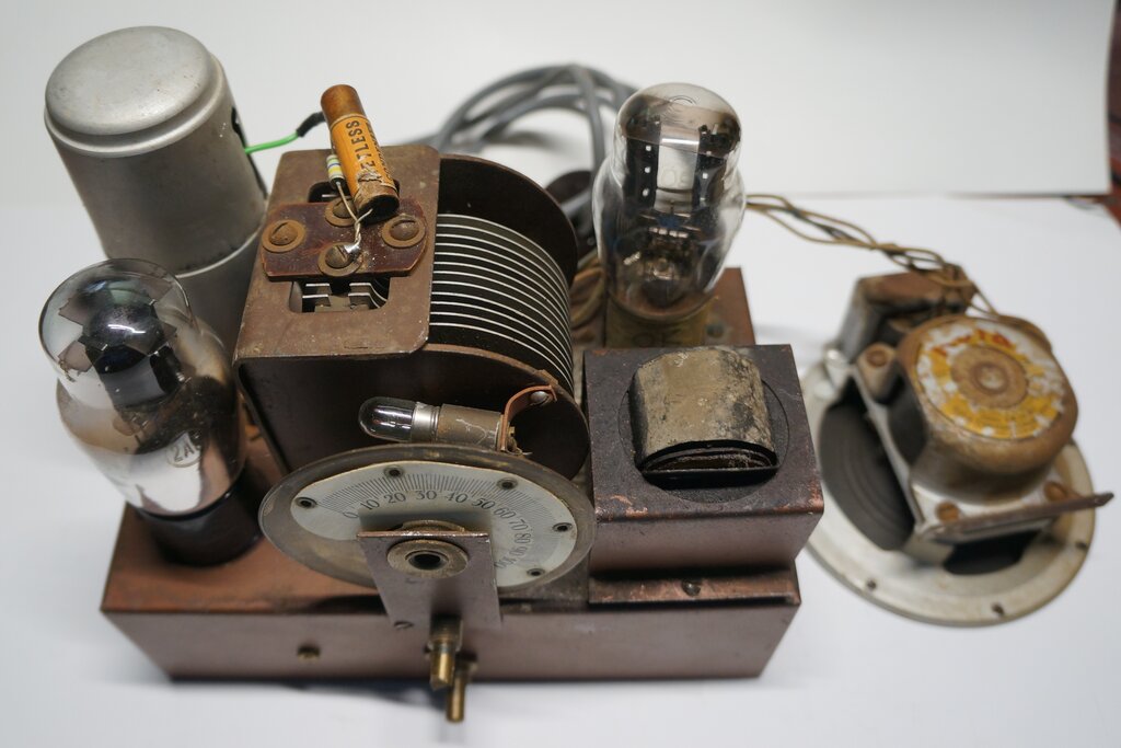
Above chassis view.
Performance.
Perhaps the strangest thing to get used
to is the 'volume' control operating in reverse. Also, the physical range
of adjustment is a lot less than the usual 270 degrees of a potentiometer.
Aside from that, it works like any other regenerative set. The sound quality
isn't hi-fi, with some distortion evident. This appears largely due to
the speaker - old electrodymanics seem to have this inherent problem.
The separator control works as expected,
but at my distant location from the Sydney transmitters, full coupling
is satisfactory. For an unknown reason, performance drops off above about
1100kc/s. It could be due to some resonance effect of my long wire aerial,
and inserting some capacitance in series with the aerial does help. Even
so, for a simple detector plus audio set, the performance is vastly inferior
to this design.