Converting foreign television
sets to work in Australia.
This article is relevant to analog television
receivers only, vintage or otherwise.
There are no longer any off air analog
transmissions in Australia, so the material presented here is now out of
date in some aspects, but it is still of interest for those collecting
vintage televisions.
Modern Flat Panel Televisions.
The criteria for using these in Australia,
directly for off air transmissions is that:
-
Set includes a DVB-T tuner.
-
Set decodes mpeg 2 at least, and preferably
mpeg 4 as well. NZ uses mpeg4 only.
-
Channel spacing can be set to 7MHz (other
countries besides Australia using the DVB-T system use 8MHz), or "Australia"
can be selected in the country set up. NZ uses 8MHz.
-
Tuner needs to receive VHF depending on area
the set is to be used in. In particular, the main capital cities use VHF
although some areas have UHF translators. Rural areas tend to be UHF.
-
Power supply operates from 240V.
If the tuner in the set is not compatible,
the set can still be used. In this situation a locally bought "Freeview"
digital set top box can be connected to the video or HDMI inputs of the
set. The same applies if the set is to be used with a pay TV or satellite
receiver, DVD player, or VCR. The set's internal tuner is not used for
these sources.
Analog Televisions - Vintage or Modern.
The remainder of this article is relevant
to analog television receivers only, vintage or otherwise.
There are no longer any off air analog
transmissions in Australia, so some of the material presented here is now
irrelevant in some aspects, but it is still of interest for those collecting
vintage televisions.
It is indeed possible to use foreign TV
sets on what is known as "System B" in Australia. During the time of analog
transmissions which existed up until December 2013 in the capital
cities, I converted one UK set and several American sets to work here.
There are various ways to approach this. First is the full scale conversion,
second is the partial conversion, and third is no conversion.
Sets for Western Europe PAL reception do
not need conversion as it is the same system. Apart from not being able
to receive Australian VHF channels 3,4,5 and 5A, the only modification
is change of power plug (use an adaptor or jug cord if you don't even want
to go that far).
One unique characteristic of Australian
TV is that since 1961, channels have existed in the 88-108Mc/s FM band.
These are channels 3,4 and 5. At the same time channel 0 and 5A were placed
right next to the 6m and 2m amateur bands. Some of these channels can be
problematic with foreign tuners. However, they can be received using an
Australian VCR and fed into the TV set. UHF channel coverage is not a problem
with mechanical or potentiometer tuned varicap UHF tuners. In the new world
of digital only transmissions, the question of channel differences is now
largely irrelevant.
Foreign TV sets do appear in Australia,
either from migrants, travellers, or eBay buyers. With post war migration
during the 1950's and TV starting in Australia during 1956, some Europeans
did bring their sets with them. Luckily, these sets worked as is. Some
American immigrants brought their sets in too. As with my Philco F3204B,
their owners simply plugged them into the 240V mains expecting them to
work. Results were blown fusible resistors and valve heaters. Those that
knew they needed a 240-120V transformer got pictures on some channels but
sound on none. Then it was off to the local TV repair shop to have it retuned.
Others, particularly in the 1960's with duty free shopping in Asia, brought
in Japanese sets which again needed modification. The wise traveller knew
to purchase sets for the European standard and avoid any compatibility
issues. In fact, over the period that Australia has had TV, many importers
have come and gone who were selling European standard sets here. This is
how models like Sharp TRP601 came into Australia, and the multitude of
Graetz, Saba, Nordmende's etc. Usually the sets simply had the local power
plug fitted before sale, but others were supplied with channel knobs with
the correct numbers. My JVC 3040CQ is such an example. I got this 5" set
in 1978 from Norman Ross Discounts in Chatswood. Although the dial
shows Australian channels, it does not show Ch 3,4,5 or 5A. In fact a sticker
came with the set stating that it would not receive these channels! It
was quite a few years after that I understood why this was. At the time,
UHF was not in use in Australia to any degree, so the UHF tuner position
was blanked off with a decorative logo.
Let's start with the characteristics
of System B:
1)Scanning rate: 625 lines, 50 fields.
Line frequency 15,625 c/s. Field frequency 50c/s.
2)Video: Negative modulation, 5Mc/s bandwidth.
3)Sound: FM 50Kc/s deviation.
4)Sound/vision spacing: Sound carrier
5.5Mc/s above vision carrier.
5)Channel spacing: 7Mc/s on both VHF and
UHF. We do not use System G (8Mc/s spacing) on UHF, as is often incorrectly
stated.
6)Colour: PAL, 4.43Mc/s subcarrier.
European System B Sets
As mentioned above, these use the same
system so do not need conversion. However, with sets that do not have a
regulated power supply, some modifications may be in order. European sets
were designed to run off 220V. Solid state colour sets with their regulated
power supplies won't be bothered by Australia's 240V mains. If there are
any mains filter capacitors rated for 220VAC, it might be worthwhile to
replace them with the 250VAC equivalents. Some transistor monochrome sets
do not have a regulated supply (e.g., JVC 3040CQ), even though there is
what appears to be a voltage regulator transistor operating in conventional
linear mode. There is even a voltage set trimpot. However, a close look
will reveal that this setup is really used as a dynamic filter with no
regulation. The trimpot should be readjusted for correct voltage; usually
11V or 12V in most sets.
Early solid state sets like the 1960's
Japanese Sony and Sharp portables have no regulation at all; just a filter
choke. It is worthwhile to check the CRT heater voltage with the set running
on 240V. If it's a bit high a resistor should be put in series either with
the CRT heater, or the power transformer primary or secondary. Generally,
this is something of minor importance.
For valve sets, extra resistance needs
to be added to the existing heater dropper resistor, and if the B+ is a
bit high, the surge limiting resistor as well. I don't recommend a common
resistor just put in series with the mains input, as the set will not draw
B+ current until it has warmed up (and even then only on positive half
cycles), and so the heaters will still receive higher voltage at turn on.
Most European sets with valves have live chassis, series heater power supplies.
The other alternative which makes any
power supply modification redundant is to make up an auto transformer to
drop the voltage. Here, a 240V to 20V (18 or 22V will do) 2A power transformer
is used. The primary is connected to the mains as usual, but the secondary
is connected out of phase in series with the mains, so the voltage is dropped
by the secondary voltage. The voltage needs to be checked before use, because
if the windings are out of phase, you'll feed the set with 260V instead.
If the voltage is 260 instead of 220, simply reverse either the primary
or secondary winding.
Prior to digital only transmissions, all
capital city channels were receivable, albeit with wrong channel numbers.
If one needed channels 3,4,5, or 5A to be receivable, the best way was
to use a VCR with UHF output as a tuner. Now that off air signals are only
digital, using such a set is exactly the same as any Australian set, as
described here.
British System I (625 line) Sets
No power supply modifications at all are
required, except of course change of power plug. System I is the same as
System B except for the channel and sound to vision spacing. If the set
has a SCART or AV input, then you can simply feed in the outputs from a
digital box, DVD player, VCR, etc. If there are no AV inputs, the next
easiest option is to use a System I RF modulator. The easiest way to get
one of these would be from the UK ebay.
When we had analog off air transmissions,
and it was worthwile to do so, a System I set could be converted to System
B. Two modifications were required: First, retune the sound IF and sound
detector from 6Mc/s to 5.5Mc/s.
Then retune the sound trap from 6 to 5.5Mc/s.
It may be necessary to increase the capacitance across the tuned circuits
if there isn't enough adjustment. For sets with ceramic filters instead
of tuneable coils, these had to be replaced with the 5.5Mc/s equivalent.
Particularly in colour receivers, if the sound trap is not dealt with,
there may be a weak herringbone pattern in the background. Colour is PAL
with the same subcarrier.
Note that most modern British sets do
not have VHF tuners. In the past, where areas of Australia had all channels
are available on UHF, e.g., parts of Sydney and most regional areas, this
could be ignored. Some sets sold in Britain were European models
(with modified sound IF) which did include a VHF tuner. Sometimes these
were disabled by cutting a PCB track, etc. If you have any ideas of replacing
the tuner with a local one to obtain VHF reception, make sure the mains
isolation circuit for the aerial connection is not interfered with, otherwise
the aerial could be live and electrocute anyone touching it. Dual standard
sets from the 1960's and 70's include a VHF tuner which can be used on
equivalent channels, and wired to become active even when the system switch
is on the 625 setting. I have modified a Ferguson Movie Star 14" colour
TV (Thorn TX9 chassis) with complete success to receive the Knight's Hill
UHF channels. This system is also used in Hong Kong and South Africa. Given
that off air analog reception is no longer, it is hardly worthwhile doing
any modifications to the sound IF or tuner.
British System A (405 line) Sets
A major undertaking in comparison. I don't
expect much demand for this modification so present the information more
as a matter of interest. Apart from the power supply, sound output, sync,
and field oscillator/output, everything is different. Although I have two
405 line sets; Ekco TC140, and Bush TV62, I have not modified them. What
has to be done:
1) Get the line oscillator and
output from 10,125 c/s up to 15,625 c/s. While the line oscillator is the
easy part with only a capacitor or resistor value change, the output stage
might not be so happy. The third harmonic tuning needs to be changed, assuming
the set is modern enough to have a tuned line output stage. The line output
transformer may not like running at the higher frequency. Assuming it does,
the heater voltage of the EHT rectifier needs to be checked if it is of
the valve type. If someone is lucky enough to have an electrostatic set,
there will be no problems. Other old sets with the horizontal yoke winding
forming the plate load of the output valve, (separate EHT supply)
are probably going to take more kindly to this. The lack of horizontal
AFC in most 405 line sets will be irrelevant with any decent noise free
signal.
2) Assuming we now have the set
happily scanning a 625 line raster, we'll deal with the video IF/detector/tuner.
At this stage, received pictures will be negative and unstable. Because
System A uses positive modulation and System B is negative, the video detector
diode has to be reversed. If it is DC coupled to the video amplifier input
(often the case) then the biassing arrangements for the video amplifier
will have to be modified as the DC present will be negative instead of
positive. Ancient sets using anode bend or grid leak detectors will need
serious modification, either by installing a unity gain phase inverter,
or by changing the CRT from being cathode driven to grid driven (or vice
versa). Polarity of signal fed into the sync separator has to be taken
into account if anything like this is done. If there's an AGC system, it
will usually be from voltage developed at the grid leak of the sync separator
valve. This should work as is. Sets with no AGC won't need any alterations
in that department either. The tuner is the next stumbling block. Unless
they've been modified, anything before the mid 1950's will be able to receive
only one or two channels, London (1) and/or Birmingham (4). Some sets have
a five position tuner, but still only band 1 VHF channels.
The best thing to do is feed these sets
with a suitable modulator, which generally has to be home made. When it
was decided to allow ITV to broadcast, 13 channel tuners became standard.
3) At this point we should have
pictures, although possibly not at the highest resolution possible due
to IF and video amplifier bandwidth not being designed for more than 3Mc/s.
Still, the resolution won't be any worse than what comes off a VHS video
tape. The sound IF and detector needs a major rebuild next. While the 405
line, or any system with AM sound does not use the intercarrier system,
this is not a problem. What is a problem is System A has the sound carrier
3.5Mc/s below the vision carrier, whereas System B has it 5.5Mc/s above.
So, you have to tune the sound IF and detector coils up 8Mc/s. It is highly
unlikely there'll be enough adjustment, and even reducing tuning capacitances
may not be enough, with removing turns being required. The AM detector
should work on FM simply by using slope detection.
All in all, a lot of modification is required.
There are now electronic standards converters but are fairly expensive
because of low production runs.
With my sets, I will try the line output
stage for 625 lines. With the narrow deflection angles, and the general
low power of the line output stage, I think there is a chance. My Ekco
has been retro fitted with a 13 position tuner, and the Bush has a 13 channel
tuner by default. I will probably adapt a commercially made VHF modulator
to feed the sets with positive going video, and use a separate VHF modulator
for sound. As video is AM, a video modulator should accept audio into its
video output to produce AM sound on VHF. By combining the outputs of the
two modulators, the set will then have the signal it needs. Baseband audio
and video can come from a VCR or digital box. Essentially, the set will
remain System A except with 625 lines. It is possible to obtain a 405 line
signal by means of a cheap home made optical standards converter. Get a
cheap 5" monochrome TV set, and an old CRT based monochrome video camera
as used for early video recorders or CCTV work. Readjust the camera's line
timebase to run at 10,125c/s and you now have a 405 line camera. Place
this in front of the TV displaying a 625 line picture and you now have
a simple optical converter. There is a lot of information on various UK
sites about using 405 line sets on 625 lines.
French 819 and 455 line sets
I can't imagine many of these finding
their way into Australia, but the kind of work is going to be similar to
the 405 line sets. Like System A, positive video modulation and AM sound
are used. The line frequency is much higher and will have to be reduced.
The video IF and amplifier has a wider bandwidth so would have problems
if it was required to work where there adjacent channels are in use (fortunately
a very rare thing).
So that they could cram in a reasonable
amount of channels into the VHF band for the 819 line system, a strange
system of sound channels of being above the video carrier on some channels
and below it on others is used. The tuner in the set therefore requires
the local oscillator to run above or below the received frequency, depending
on the channel. How very French! Obviously, anyone capable of modifying
such a set doesn't need further instruction, but suffice to say, the easiest
way is to take the VHF modulator approach and leave the set original except
for the horizontal stage.
There were some 819 line sets that worked
on 625 lines as well, which makes things a bit easier. I am under the impression
that like Australia, France discouraged live chassis TV sets and the very
few examples I've seen have used a transformer isolated supply with 6.3V
parallel heaters.
French System L (625 line) sets
The last remaining positive modulation
video and AM sound system was still in use. It also uses SECAM colour.
Monochrome sets for this standard essentially need the video polarity and
sound IF dealt with as with System A. The sound to vision spacing is 6.5Mc/s
in this system, so the sound channel has to be tuned down 1Mc/s. For colour,
forget it unless you are motivated enough to rebuild the decoder to function
on PAL...and there isn't going to be much left of the original. There is
virtually nothing in common between SECAM and PAL.
American System M sets
These, I have had some experience with,
and certainly for monochrome use are not too difficult. Sets I've converted
are Philco F3204B, Sentinel 400TV, Admiral 17T1, Panasonic TR555,
and Sony 503. I also have a Zenith 15K37 which was converted by someone
else.
The mods required are:
1) a transformer to convert 240V to 120V,
2) reset the vertical hold and height, 3) if you require System B off air
reception, retune the sound IF and detector from 4.5Mc/s to 5.5Mc/s,
4) retune the VHF tuner if of the turret
or incremental type (only necessary if Australian VHF channels need to
be received).
1)Some thought needs to be given
to the stepdown transformer as there are both double wound and auto transformers
available. Auto transformers do not provide isolation between primary and
secondary. This becomes a safety issue, especially where live chassis sets
are involved. It is possible for one side of the 120V output to be floating
at 240V above earth depending on how the transformer is wired and also
whether the live and neutral are reversed in the 240V supply feeding the
transformer. Because the insulation in such sets was not intended for 240V,
I do not recommend auto transformers for them. Neither do I recommend powering
such sets from a Variac as these also provide no isolation, along with
the ease of accidentally increasing the voltage to the set. Also for this
reason, using resistors or light bulbs to drop the voltage is unsafe, apart
from the fact the voltage from these sources is dependent on the set's
current consumption and will rise to 240V with the set turned off, thus
stressing the insulation of switches and aerial and chassis isolation components.
If the set has a fully isolated transformer supply and any mains switch,
aerial and chassis isolation components are rated for 250VAC, then I don't
mind an auto transformer provided I know the 120V neutral is connected
to the 240V neutral.
2)The vertical hold and height
needs to be reset because when the set was working with a 59.94c/s field
rate, the scan time was 16.66mS. Now it is to work on 50c/s, the period
is 20mS, so the vertical scan spends more time being traced out over the
screen and therefore gives the appearance of excessive height. Vertical
linearity may need adjustment, and/or some of the waveshaping components
replaced. The System M line frequency of 15,734c/s is so close to 15,625c/s
that the line oscillator will usually lock in straight away. If not, a
touch up of the horizontal hold will fix that.
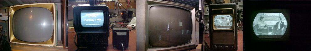
US TV sets converted for use in Australia. From L to R: Philco Seventeener
II (model F3204B) ca. 1959, Panasonic TR555 ca. 1978, Zenith 15K37 ca.
1963, Sentinel 400TV
ca. 1949, and Admiral 17T1 ca. 1949. Note the UTC R44 stepdown transformer
next to the TR555. The Zenith actually had the power transformer in the
set replaced with one having a 240V primary.
3) The sound IF and detector needs
retuning. Most times, it is necessary to reduce the capacitance across
the sound IF and detector coil windings, as you'll run out of slug adjustment.
It can be done by trial and error, but
if you want to minimise that, you can work out a good starting point.
By knowing that the circuit was tuned
to 4.5Mc/s and knowing the value of capacitance across it, you can work
out what the inductance is.
Then by working backwards, you can work
out the capacitance for when the same inductance is tuned to 5.5Mc/s.
The formula is: L=(1/{2 x pi x F})^2
where L is inductance in Henries, F is frequency in c/s, and C is capacitance
in Farads.
C
Once L is known, then L and C can simply
be swapped in the formula:
C=(1{2 x pi x F})^2
L
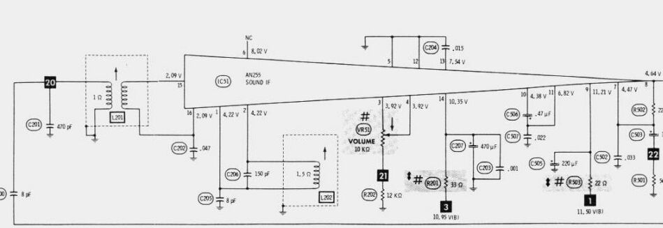
As an example, we'll use the Panasonic
TR555. L201 is the sound IF transformer and L202 is the quadrature detector
coil. As shown, both are tuned to 4.5Mc/s. For L201:
L=(1/{2 x pi x 4.5E6})^2
470E-12
L=2.66E-6 H
Now for 5.5Mc/s operation, C=(1/{2
x pi x 5.5E6})^2
2.66E-6
C= 3.15E-6, or 315pF. Nearest preferred value is 330pF.
So, C201 is reduced from 470pF to 330pF
and L201 retuned. L202 is dealt with in the same way. For sets with ratio
detectors, like the Sentinel
400TV, it appears that the operation of the secondary of the detector
transformer doesn't quite follow this. I actually found in the 400TV the
capacitor value had to be lower than calculated.
4) The remaining adjustment is to
deal with the VHF tuner. If it's a modern set with a potentiometer tuned
varicap tuner then no more needs to be done. Capital city channels will
be received, but with wrong channel numbers. Channels 0, 4,5, and 5A are
outside the US VHF TV band so will generally not be receivable unless the
set has continuous tuning between band 1 and band 3.
Incremental or turret tuners will need
to have their local oscillator retuned on the nearest equivalent channel.
I've explained this in the Sentinel 400TV article.
UHF tuners need no adjustment as they
are continuous and actually cover more than the Australian UHF TV band.
Again, the only difference will be wrong channel numbers.
If yours is a VHF only set and wish to
receive Australian UHF channels, get a UHF converter off Ebay.
Modern sets with frequency synthesised
tuning are a problem as the software in the microprocessor determines the
frequencies of received channels. Not much can be done about that, so the
way out of the problem is to obtain an RF modulator for US standards and
feed it with baseband audio and video from a VCR, DVD player or digital
box.
In fact, if you only want to use your
US TV set with a digital box, VCR, etc., there is no need to bother with
retuning the sound IF and VHF tuner.
Simply use the RF modulator approach with
baseband audio and video signals fed in. If the set has AV inputs you don't
even need a modulator. System M modulators are available on the US ebay.
Colour with that? At
this point we have sound and a monochrome picture. This is where it ends
for most sets, but for colour sets brought in to Australia here comes the
difficulty. Four options exist: 1) simply watch the programs in monochrome,
2) get a standards converter 3) use a digital box that can have its output
set to NTSC, 4) modify the colour decoder.
If a standards converter is used, it must
output the colour on 3.58Mc/s. There is a version of NTSC used in PAL countries
for playing NTSC video tapes on modified PAL televisions. It's often called
"NTSC 4.43". Some early VCR's of the "NTSC Playback" use this format,
particularly U-Matic machines. They output a 60 field 525 line NTSC picture,
but the colour subcarrier is raised to 4.43Mc/s. This is so the PAL decoder
will work. All that is done in the set is to stop the bistable PAL switch
so there is no phase inversion of the red colour difference signal on every
alternate line. Additional poles on the PAL/NTSC switch reset the
height and vertical frequency. The Sony KV1830CVM was one popular set modified
to go with the V01810 U-Matic VCR and had this feature. Later "NTSC Playback"
VCR's of the more recent VHS type follow this method, but also do actually
reverse the red colour difference signal every second line so that the
picture can be viewed in colour on an unmodified PAL set. This is of course
providing there's a user adjustable vertical hold control or the set is
designed for this kind of signal and has auto sensing of the vertical frequency.
Analog PAL to NTSC standards converters work in a similar way and do not
change the line and field rate, so the set will have to run on the 625
line standard by adjusting the vertical hold and height. Digital standards
converters are a better option if you want to do absolutely no modifications
to the set.
If you only want off air reception, many
digital boxes can be set to provide a genuine NTSC output.
The fourth option of modifying the colour
decoder is obviously only suitable for those who understand the process.
Briefly, everything tuned to 3.58Mc/s has to be retuned to 4.43Mc/s and
the crystal, if there is one, also replaced. At this point the set should
display colour but every second line will have the wrong colour. A phase
inverter has to be built to invert the red colour difference signal every
second line. It alternates the signal + and - 90 degrees at half line frequency.
A 7.8Kc/s bistable locked to the line oscillator is used to provide the
switching signal. An ident circuit is also required to make sure the signal
is being inverted on the correct lines, otherwise it is purely by chance
it will lock in the correct phase. If you don't mind changing channels
back and forth until you get the right phase, you could skip that piece
of circuitry.
Strictly speaking, a delay line should
be included in the chroma processing circuit. However it adds to the complexity.
As I've described, the colour decoder will work in PAL-S and colour phase
errors are averaged out optically. If there are Hanover bars present, the
existing NTSC hue control can be used to minimise them. In any case, the
colour will be better than NTSC.
I did a modification on an NTSC video
monitor quite a few years ago. The colour decoder was IC based so I replaced
the IC with a similar one meant for PAL. The PAL IC had less pins so there
were pieces of tinned copper wire to connect its pins to the correct holes
in the PCB. The colour crystal was replaced with a 4.43Mc/s version, and
a suitable signal found from the line output stage to activate the PAL
bistable. I could have installed a delay line, but simply used a 100pF
capacitor instead. The resulting PAL-S picture was excellent. If doing
something like this, you need example circuits as provided in the IC data.
Discreet valve or transistor decoders will need more work as you're going
to have to design your own circuitry.
I am hesitant to recommend buying pocket
LCD type TV sets made for the 525 line system. If it's a colour set, it
will be impossible to modify the colour decoder. The miniaturised and surface
mount parts will be a pain to work with anyway. The real limitation with
some such sets is it might not be possible to adjust the field and line
rates. Don't forget the display in these is digital.
Sets that divide down from the line rate
to get the field rate could also be a problem. I don't know if any US sets
did this, but some European type sets sold in Australia did. This technique
was used to provide a very stable vertical frequency.
Modifying US VCR's to work here is an
interesting thought. Apart from the front end frequency changes, the head
drum servo system would have to be made to work at 1500 rpm instead of
1800 rpm. I expect some alteration to the chroma circuits regarding frequency
might have to be made. The dropout compensator would not work properly
due to the differing line period. You could replace the delay line with
a local equivalent or just use good quality tapes.
Safety Issues: Many foreign sets
have a live chassis & overseas safety standards often non existant
Australian TV technicians were brought
up with transformer isolated sets as being standard. We have therefore
had the pleasure of being able to work safely on an earthed chassis and
not have to worry about connecting earthed test instruments to them. Connecting
extension speakers or headphones was also a risk free modification. With
the exception of some Astor portables in the 50's, there were no locally
designed live chassis sets in Australia. The other few models sold were
UK or US designs modified for Australian use (Some Pye, Ekco, Pope/Motorala
models and the Thorn R2M). The reason for mentioning this is that many
overseas sets are live chassis and have the power line connected to the
chassis. The fact they might have a power transformer of either the switchmode
or iron core laminated type should not give assumption to them being isolated.
Some sets have a power transformer, but it's sometimes only for the heaters
or the solid state sections of a hybrid set. One not so obvious trap I
have seen is where the power supply is indeed isolated with a transformer,
but the valve heaters are connected in series on the mains side. It could
be said the chassis is safe to touch as the valve heaters are not connected
to the isolated circuitry. That is, until one of the valves develops a
heater to cathode short. Auto transformers are commonly used as they
are cheaper and lighter than double wound transformers. Therefore,
it is essential that any modifications done to these sets do not compromise
the mains isolation. Things like aerial isolation chassis to cabinet bypass
capacitors for U.S. or Japanese sets may be operating outside their voltage
when exposed to 240V. Static discharge resistors are often connected between
the chassis and user touchable parts. Resistors do have a voltage rating.
Are yours up to it if you're going to run the set from anything but a double
wound stepdown transformer? There's also the question of speaker transformer
insulation, especially if an earphone socket is provided, or the speaker
is mounted on the side of a metal cabinet. What if the knobs come off?
Are there control shafts to expose the user to 240V? For this reason, I
recommend an isolating stepdown transformer. The same applies to mains
operated valve radios. Take a look at some of the American FM converters
and valve radios I've described on this site if you're still not convinced.
One lethal contraption once sold overseas was a battery eliminator for
transistor radios. It took the place of the 9V battery and consisted of
a rectifier and filter capacitor in the usual way. The trap was, instead
of a transformer, a voltage dropping capacitor was used. Small and cheap
maybe, but would you like to use a radio with its earphone socket floating
at mains voltage? Unbelievably, these gadgets were even sold in some 220-240V
countries. It is incredible to see constructional articles on radios where
headphones are connected to a live chassis radio with no transformer, but
they abound like you wouldn't believe. One English magazine (Practical
Electronics) during the 60's had a project where neon lamps were involved.
Due to the neons requiring 90V, the designer thought it convenient to avoid
having a transformer and run the circuitry straight from the mains. There
were exposed connections on this project. So how did he get around that?
A clever trick I've seen in a few U.S. designs too...instead of returning
the circuit to mains neutral, you return it to earth. That way anything
user touchable is supposedly safe. That is, until the earth connection
fails, or the unit is plugged into a two wire extension lead. Then the
whole lot happily rises up to whatever the mains supply is. And if the
earth connection is faulty further down the line? Much joy as every
other appliance on the circuit becomes live. The earth circuit is there
for protection, not a defacto neutral. But then one clever American had
thought about that too. Couldn't go without his live chassis power supply
feeding a metal cased disposals receiver he had converted to 120V mains
operation, could he? You'll never guess the solution to this one...well,
the idea was a 100W projector lamp connected from the case of the receiver
to earth. If the receiver was plugged in so the case was live, the bulb
would light up, blindingly so, warning the user to reverse the plug. All
very well, but what if the earth connection to the bulb had failed where
no one would see it? What if the bulb was faulty? What if someone was touching
the case as it was being plugged in before they waited to see if the bulb
would light? What if a non technical user didn't even know what the bulb
was for and thought that the radio was working correctly with it on? And
one other thing; the designer considered the bulb warning system "optional".
Using polarised mains connectors is not a satisfactory answer as the supply
polarity cannot be guaranteed (non standard house wiring, twin flex extension
cords, etc.); and again , if there's some defect in the neutral connection
, the chassis becomes live anyway. Where bridge rectifiers are used, the
chassis will be live regardless of mains supply polarity.
Home