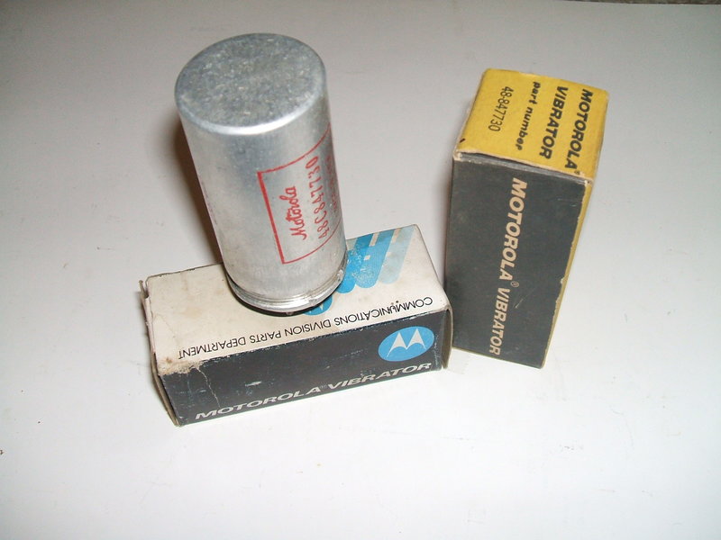
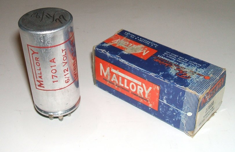
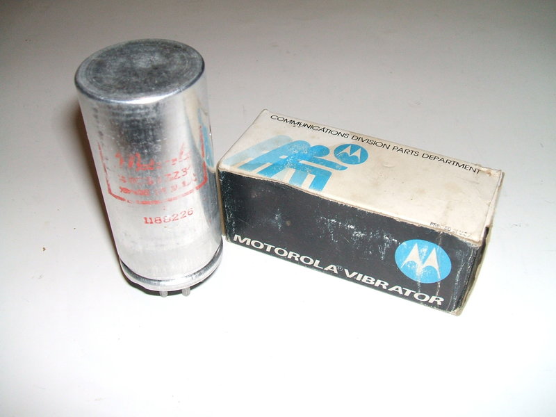
The styling of the box at left implies Motorola vibrators were still being sold well into the 1970's.
The styling of the box at left implies Motorola vibrators were still
being sold well into the 1970's.
In this article we will be looking at the
so-called "Communications" type vibrator. While the operation is the same
as any other vibrator, and the appearance is the same of any other radio
type, there are several important differences.
This type of vibrator was introduced in
the mid 1950's in the U.S. and was intended for heavy duty applications,
such as radio transceivers. It is a split reed dual-interrupter type. That
is, there are two sets of contacts, each with an individual isolated reed.
Current rating is somewhat higher than typical radio vibrators such as
those found in car and domestic broadcast receivers.
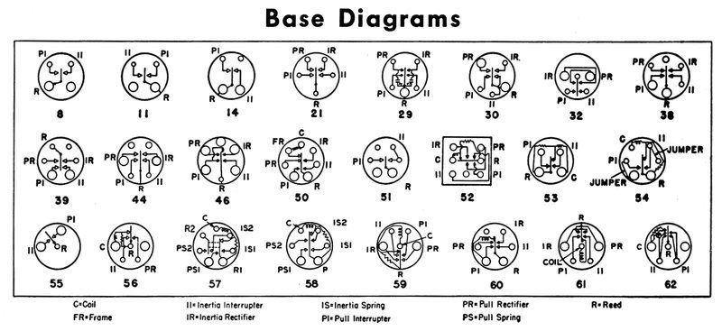
The base is a small UX-7, and the vibrators
are series (separate) drive. Coil voltage is 6V, but with an ingenious
circuit configuration they can be operated on 12V with no modification,
and no series resistor. This change of voltage was required because at
the time, U.S. car manufacturers were switching from 6V to 12V electrical
systems. Ordinarily, if a transceiver was bought for a 6V car, and later
installed in a newer 12V car, modifications would be required to convert
it. Typically, this entails replacing the vibrator, vibrator transformer,
any dial lamps, and replacing any relays, or connecting resistors in series
with their coils. The heater circuit for the valves also has to be rewired
to a series parallel circuit, unless there are 12.6V heater types for all
the types used - in which case all the valves can be replaced. This additional
cost and time required to perform the conversion can be eliminated by using
the new type of split reed vibrator circuit. The only change required is
in the power plug wiring, depending on whether it is a 6 or 12V supply.
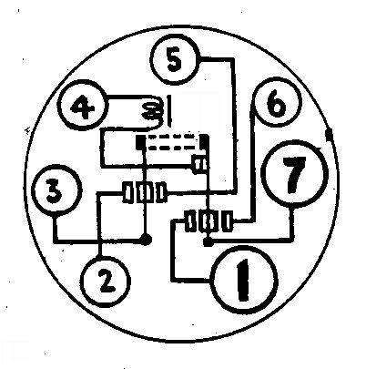
| Pin | Connection |
| 1 | Reed A and coil earth |
| 2 | Contact 1A |
| 3 | Reed B |
| 4 | Coil supply |
| 5 | Contact 2B |
| 6 | Contact 2A |
| 7 | Contact 1B |
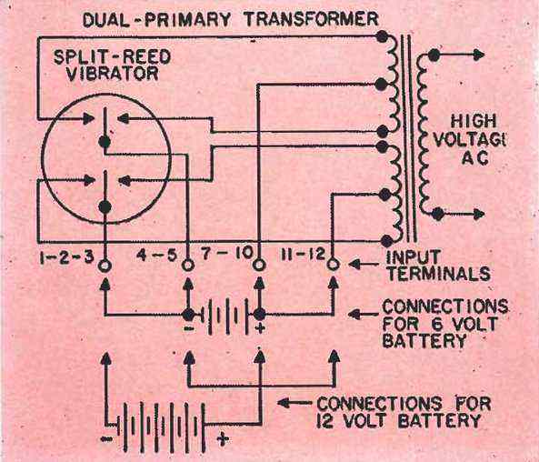
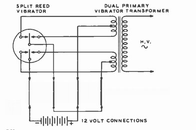
The transformer has two primary windings,
which are essentially operated in parallel for 6V, and in series for 12V.
First, examine the circuit when used on 6V. Looking at the plug wiring,
it can be seen that the 6V supply feeds the centre-taps of both primaries.
Each primary is connected to its own set
of contacts. Each set of contacts has its own reed, which are connected
together, and thence to the negative battery terminal. Since the reeds
are mechanically, and electrically, connected together, current flows in
both of the primary windings in the same direction, and at the same time.
The input current is therefore divided in half across the vibrator contacts
and primary windings. Effectively, this allows a doubling of power than
would otherwise be the case with a single winding and a single set of contacts.
Aside from this, the contacts are larger
than a standard radio vibrator, further increasing the power rating. The
drive coil is not shown, but is connected to the 6V supply.
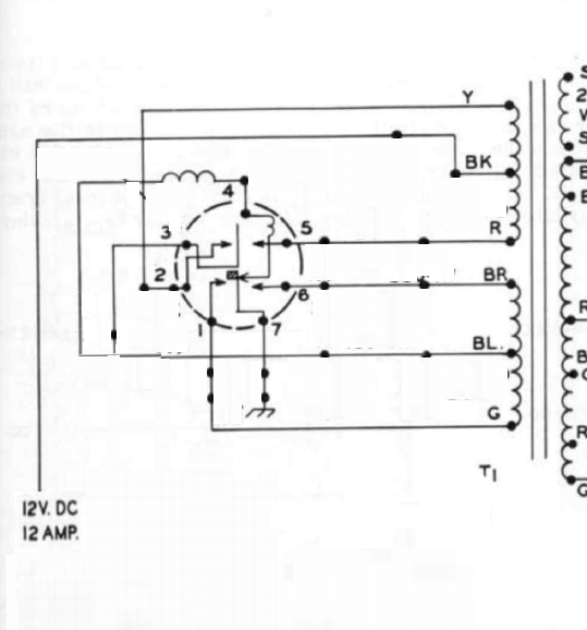
Now, consider 12V operation. Note the altered
power input plug connections. Starting with the 12V supply, it connects
to the centre-tap of the upper secondary. This is switched by the upper
contact set, and the return is via the upper reed. In the 6V circuit, this
reed would return to the negative in the normal way. But, we want 12V operation!
So, instead, the reed returns to the centre-tap of the lower primary winding.
This is switched by the lower set of contacts, and current returns to the
battery via the lower reed.
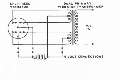
It should now be clear that we now have
two 6V vibrator power supplies operating in series, but with a common transformer,
and with both vibrator reeds mechanically and contacts synchronised. It
can be seen that the upper reed and the centre-tap of the lower primary
are effectively at the electrical mid point, and therefore at 6V. It is
here that the drive coil is connected.
Think of the circuit as two 6V vibrator supplies but with a common
transformer. For 6V they are in parallel, and in series for 12V.
From this, we can see that absolutely no changes to the power supply itself are required when switching between 6 and 12V, provided the supply plugs are wired appropriately. Not shown is the heater wiring for the valves. The valves are 6.3V types connected in a series/parallel arrangement. There are two 6V legs of the circuit so to speak, and with suitable arrangement of valve heaters (and if necessary, equalising resistors), each leg is made to draw the same current. This is standard practice for operating 6.3V valve heaters from a 12.6V supply. When the supply is 6V, all that is necessary is to connect the two legs of the circuit in parallel. This is easily done with additional links in the power plug.
The G.E. 100W Power Supply.
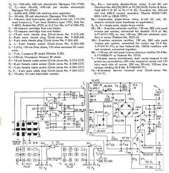
Circuit of the G.E. 100W power supply.
The full circuit diagram of the 100W power
supply shows all the ancillary components required; the timing circuit,
the rectifiers, and RFI suppression components. Also shown is transmit/receive
switching by relays. The vibrator drive coil connections can be traced
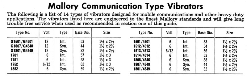
out for both 6 and 12V. Vibrator types suited to this circuit include:
Mallory
1701,
Oak V6853, Radiart 5722, and G.E. A-7141584.
With a 100W rating, it is obvious that
the vibrator current is much higher than that of a broadcast receiver.
At 6V, this is an input current of 16.7A, and at 12V, the input is at least
8.3A. Assuming an 80% efficiency, these input currents would be 21A and
10.4A respectively. Note the individual contact current on 6V is not
21A, because of the current being shared between two primaries. Assuming
perfectly equal current distribution it will be the same as that for 12V;
i.e. 10.4A.
There's a Mistake...
A fellow enthusiast from Italy, Giovanni
IZ5PQT, had ideas about building a version of this power supply. It was
then that an error became apparent, for 12V operation. For the purposes
of analysing the power supply, it makes things easier to remove all the
superflous components. We are then left with this:
The vibrator cannot start in the 12V configuration.
As far as the transformer is concerned,
and the vibrator contacts connected to it, all is correct. The error lies
in the method of obtaining the 6V for the drive coil. Tracing the 12V supply
through, we see it feeds the centre tap of the 'upper' primary winding.
The outer two connections feed the contacts at pins 2 and 5 in the normal
way. The upper reed then feeds the centre tap of the 'lower' primary winding.
Since the upper and lower circuits are in series, the voltage at this point
is 6V. It is a convenient place to obtain the 6V for the drive coil.
Have you spotted the problem? At rest,
there is no way current can get to the lower circuit to start the vibrator.
The current stops at pins 2 and 5, and goes no further.
It would appear that the designer never
actually tested the circuit on 12V. Note that the circuit was not from
G.E. themselves, but contributed by an amateur radio operator. The correction
for the circuit is simple; a 5W dropping resistor to feed the drive coil
when operating on 12V; 15 ohms for the Mallory 1701, Radiart 5722/6722,
and equivalents. 22 ohms for the Oak and its equivalents.
So how is it meant to work? What did Motorola
do in their commercially made sets? The power supply is such that the valve
heaters are part of it when operating at 12V. For 12V, the heaters are
connected in the usual series parallel arrangement, so that there are two
6V heater circuits in series, each drawing the same current. The mid point
is thus 6V. It is from here the vibrator coil is driven. Furthermore, the
6V junction of the upper and lower primary windings is also connected to
this point. Due to transformer action, it so happens that both branches
of the heater circuit are fed with equal voltage, even though their current
draw might not exactly be the same. The G.E. circuit shows no connections
to the heater circuit.
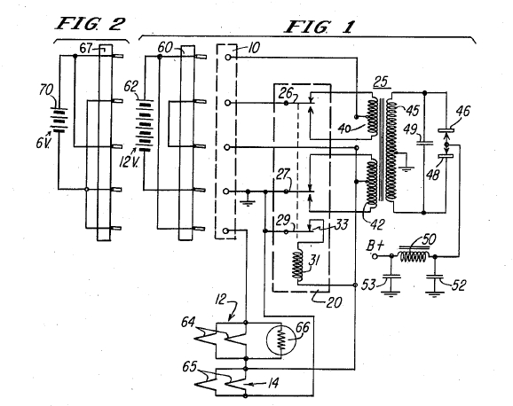
From Motorola's patent, we see the vibrator is started by the 6V
at the junction of the two heater circuits.
It is interesting to note that the Motorola patent clearly shows an Oak vibrator. It would appear that Motorola wanted the best type of vibrator available for this circuit. Also, Oak was experienced with separate drive and split reed vibrators. The Mallory 1701 and Radiart 5722/6722 split reed types were presumably manufactured in response to the Oak. Neither Mallory or Radiart were keen on separate drive or split reed designs, prior to Motorola developing this power supply.
Mallory
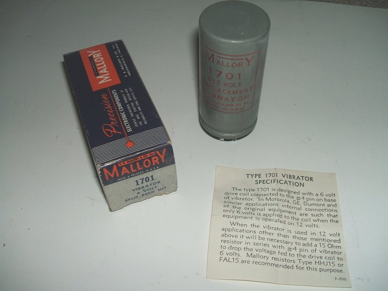
The Mallory 1701 is a common type of communications vibrator.
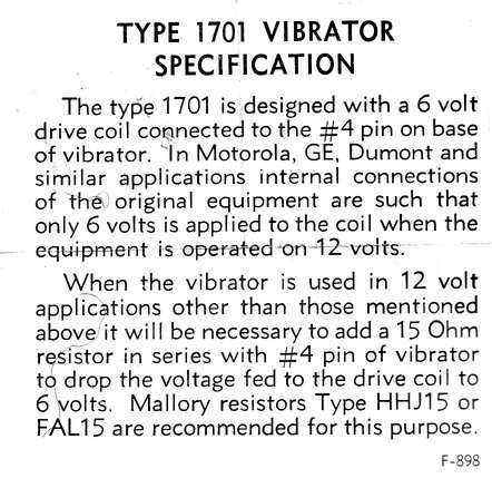
Included with the Mallory 1701 is information
regarding the drive coil. The series resistor required for normal 12V use
is 15R. This will be required when the vibrator is used in a conventional
circuit, with only one primary winding and a 12V supply. The vibrator pictured
appears to have been purchased in 1977 according to the writing on the
can. It is new in box. This may indicate that Mallory was still making
vibrators at the time.
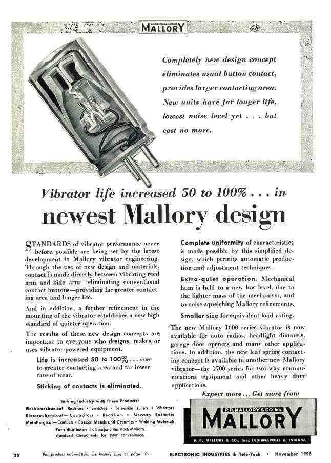
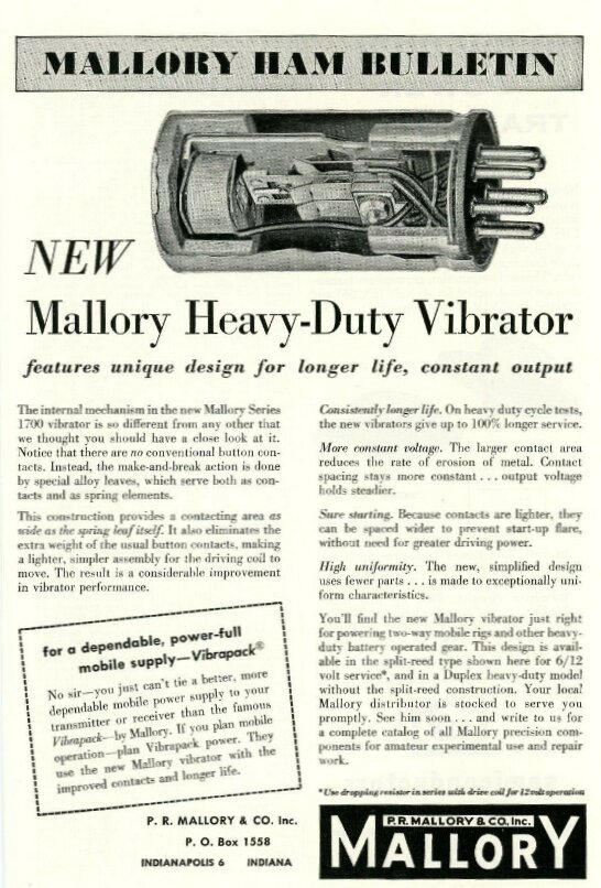
The last development in vibrator technology was Mallory's 1600 and 1700 series with the new kind of contact.
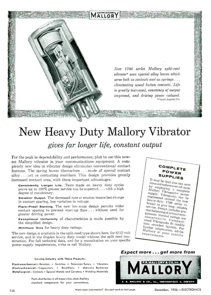
The 1701 was among the last vibrators developed by Mallory. It was also one of the few series drive vibrators produced by Mallory. Presumably because of the Oak patent concerning spark suppression of the driver contacts, Mallory use a resistor across the driver contacts to prevent sparking. In the Motorola branded example described further down, the resistor is 270R 1/2W.
Radiart / Cornell Dubilier Electronics
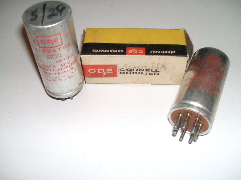
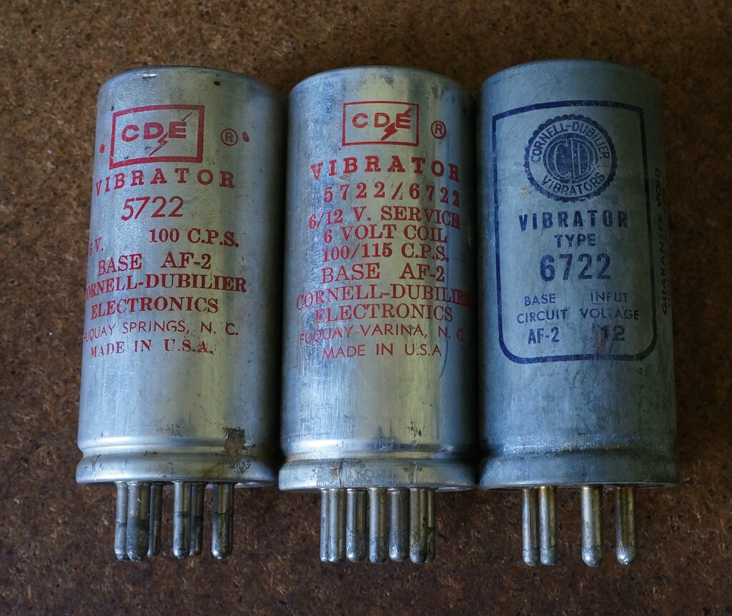
Although not clearly visible, the vibrator at right is labelled
5722/6722. It still has a 6V driver coil.
Radiart was taken over by Cornell Dubilier Electronics in 1953, and as such CDE vibrators carry over the Radiart type numbers. A "5" prefix indicates 6 volt, and "6" indicates 12V. Because of the dual voltage operation, there may be either a 5 or 6 prefix for communications types. For example, the 5722 may also be listed as 6722 as the following advertisement shows:
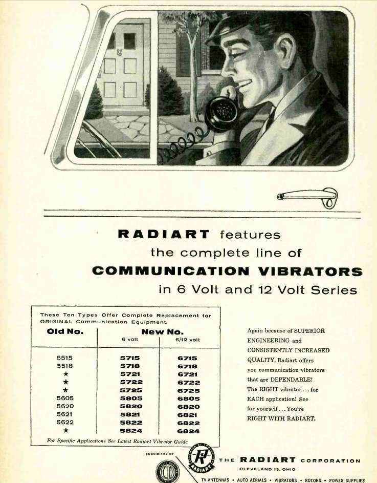
However, it is important to note that the driver coil voltage is still 6V regardless of type number. The "6/12 volt" types listed must not be run directly on 12V.
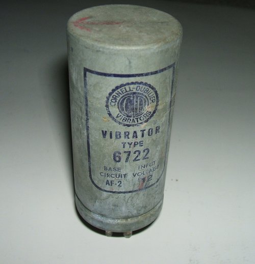
Type 6722 is the same as 5722. It has a 6V drive coil.
Types 5722, 5722/6722, and 6722 are really all the same.
Note the 5722/6722 states the coil is for 6V, although it is suitable for 6/12V service. As explained previously, equipment designed for these vibrators runs the coils from 6V when the supply is configured for 12V. The three vibrators pictured above were tested and confirmed to be 6V types, both from coil resistance and current draw. It is also noteworthy that both the 5722 and 6722 are listed in the Mallory catalog as a 1701 equivalent, which as is clearly stated, a 6V type.
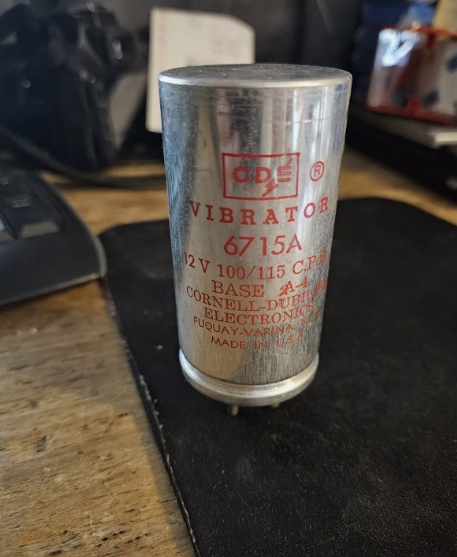
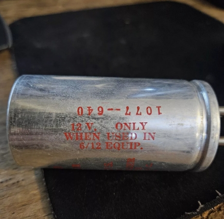
Note that the 6715A is "12V only when used in 6/12 equip."
It would appear the numbering system was changed to conform with the "5" prefix being 6V, and "6" being for 12V operation of the equipment, rather than the actual vibrator coil voltage. The "12V" operation relies on the equipment to provide 6V for the coil.
One would have to agree that this numbering
system and stating of "6/12V or 12V" is confusing, misleading, and possibly
damaging. In the normal way, when replacing a vibrator in a communications
transceiver with the nominated type, there would be no problem.
However, the damage is going to occur
when someone finds one of these vibrators to use in a substitution or a
new project, and seeing "12V" or "6/12V" printed on the vibrator, assumes
that 12V can be applied to the coil.
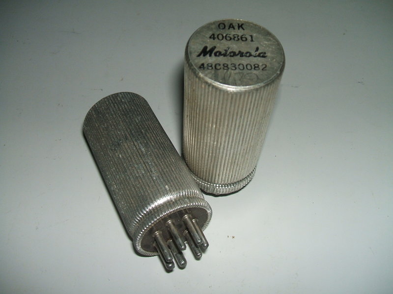
The corrugated can design was used by Oak
with some of their later U.S. made vibrators. Presumably, it is intended
to be a more effective heat radiator. The type shown here is a 406861.
It is also branded Motorola type 48C830082.
Oak vibrators are covered in this
article.
The construction is the same as the ordinary
radio and inverter vibrators, which have always been series drive. Unique
to Oak is the dual winding driver coil, which eliminates the external spark
suppression components otherwise required for the driver contact. Driver
coil resistance is 22R.
Diameter of the power contacts for the
communications type is 5.6mm. An ordinary Oak car radio vibrator has a
contact diameter of 4.3mm.
Melvin Instruments.
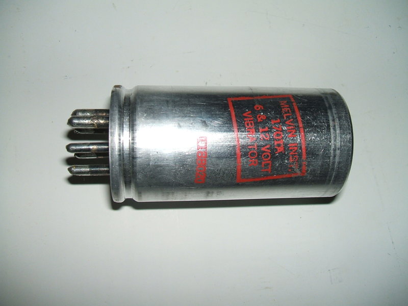
This 1701A is branded Melvin Instruments, but appears to be a rebadged Mallory.
With Motorola being a very prominent manufacturer of mobile two way radio equipment at the time, it is no surprise to see a prevalence of Motorola branded vibrators. It appears that they are rebadged Mallory or Oak types.
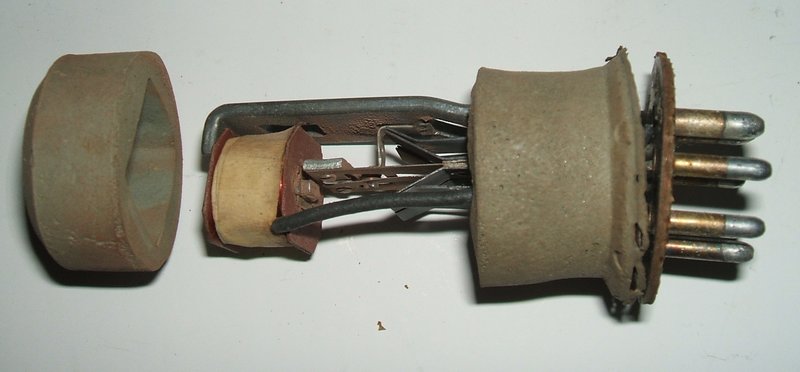
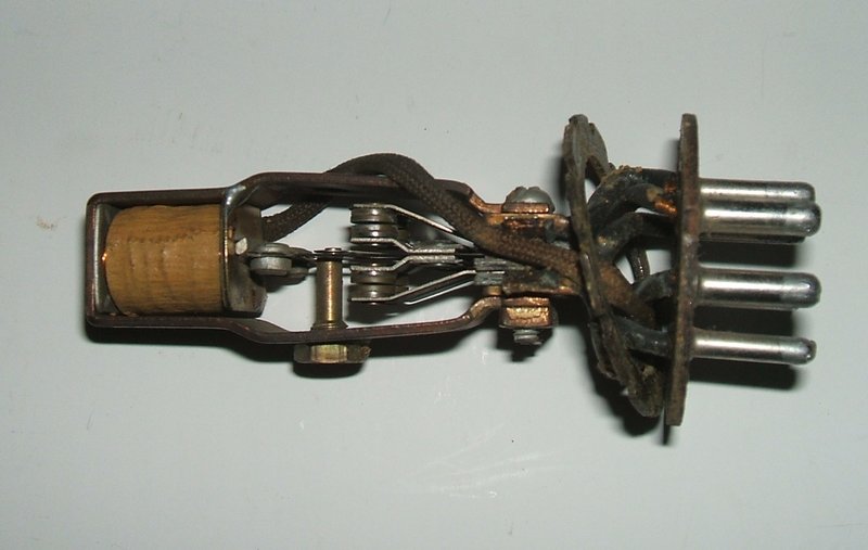
This shows the inside of a Motorola 48C847730. It is clearly made by Mallory, and presumably is a 1701 type. Coil resistance is 10R, and the spark suppression resistor is 270R (mounted under the stack). These two resistance values correspond with a Mallory branded 1701A. An experiment was done in which the reed swing was measured at 6V. It was about 8.5mm. It was found that to get the same reed swing on 12V, the series resistor was 15R, which confirms Mallory's recommendation.
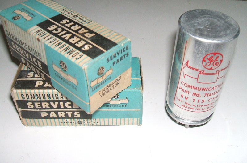
Type 7141584-003. Same as 7141584-P3. It is shown in the list of vibrators suitable for the 100W power supply, and presumably equivalent to Mallory 1701. It is quite likely the unit shown above is actually the latter.
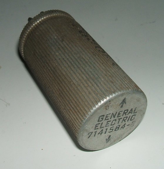
This 7141584-3 is apparently an Oak rebadge, as evident by the corrugated
can.
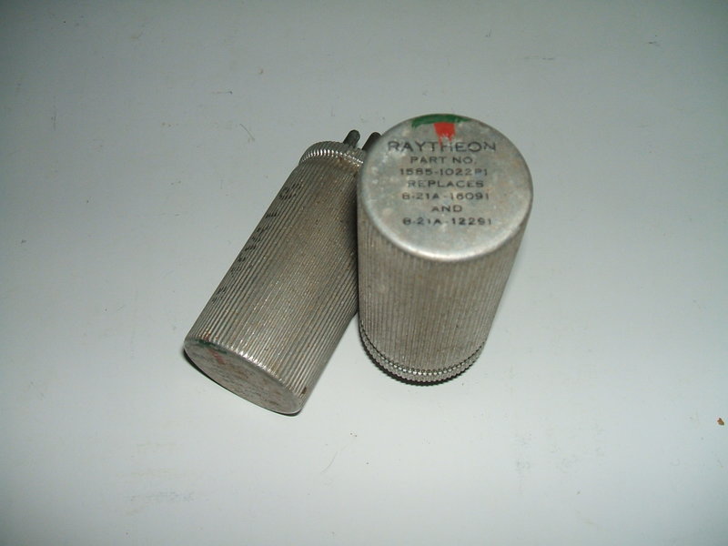
Apparently another Oak rebadge due to the corrugated can. Types 1585-1022P1, 8-21A-16091, 8-21A-12291. While it looks like these are communications types, this has not been confirmed. Coil is 6V.
7-Pin comms types:
Motorola 48C830082. Equivalent
to 48847730, 48-847730, 48C847730, 6130-00-284-1147, 00-284-1147, 6130002841147,
002841147 (By implication, also Oak 406861 and Mallory 1701).
Frequency 96-105Hz Input current 24A Drive
Coil 6V. Dual reed, dual interrupter.
General Electric 7141584-003. Same as 7141584P3. Frequency 115Hz. Drive coil 6V. Shown in the list of vibrators suitable for the 100W power supply.
Military and other types:
Motorola 48B3333. Frequency 109.25-120.75
Hz. Input current 15A. Drive coil 6V. Single reed non-synchronous.
Motorola 48B60392. Equivalent to:
48B60392, 48B61279, 48B61279-24V, 271-1563VB11, SCA12560D,
VB11, VB11A, M682
Frequency 115Hz. Drive coil 24V. Single
reed non-synchronous. Octal base.
Motorola 48B82036. Equivalent to:
48-880261, V6126, 348
Frequency 106.9-123.0 Hz. Drive Coil 6V
Input current 12.5A. Single reed non-synchronous. UX-4 base.
Motorola 48K60393. Equivalent to:
271-1563VB12, 860VIBRAT0R, RA96A, SCA13489, VB12A, VB12
Frequency 108.1- 121.9 Hz. Drive coil
6V. Input current 5A. Single reed non-synchronous.. Octal base.
Motorola 248B1006. Equivalent to:
3356C24V, M3356C2, 3356C24V, M3356C2, V6626, 248B1006,
348D107, SC-C-34091
Frequency 95Hz. Drive coil 24V.
Input current 2.4A. Single reed synchronous self rectifying. UX-6 base.
Motorola 248B1015. Equivalent to:
EX2920, V6642.
Frequency 95Hz Drive coil 12V.
Input current 2.6A. Single reed synchronous self rectifying. UX-6
base.
Motorola 248C3775. Equivalent to:
G3356C12-6V, 248C3775, SMC116293
Frequency ? Drive Coil 12.6V.
Input current 2.4A Single reed synchronous self rectifying. UX-6
base.
Motorola 48B893518. Equivalent to:
MV2, T4003. (T4003 is a Mallory type)
Frequency 115Hz. Drive coil 2V.
Input current 6A. Synchronous self rectifying. UX-7 base. One of the pins
is for connecting a 0.1uF spark suppression capacitor to the drive coil
contacts.
This data was obtained from https://www.parttarget.com/Motorola-Inc-055704_nsn-parts_MDA952-4_60-P32530G001.html
What can they be used for?
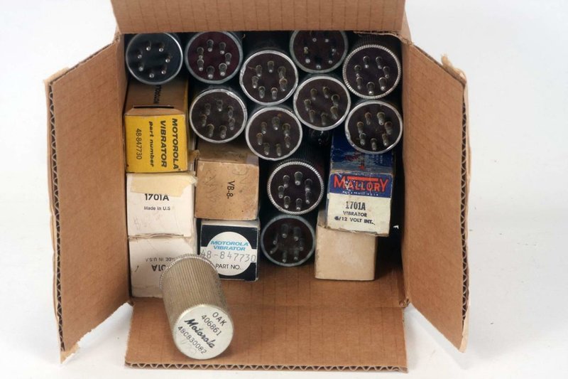
This box of vibrators was bought for only US$14.00
Vibrators are always available on the U.S.
eBay, and the communications types should not be overlooked. In fact, they
don't seem to have much demand since they are not a direct plug in replacement
for car radios. Because of this, it should be possible to purchase them
inexpensively. So what can they be used for? Aside from their original
application, they suit any car or domestic radio circuit where a non-synchronous
vibrator is used. By connecting the reeds together and paralleling each
set of contacts, the vibrator can be used in the normal way. Of course,
if replacing the vibrator in an existing set, the socket will have to be
changed. As the contact rating is higher than any car radio type, life
should be much longer. The series drive coil also helps considerably in
this regard.
These vibrators can also of course, be
used in 12V circuits, simply by connecting a resistor in series with the
drive coil pin. While this resistor is 15R for Mallory and rebadges, it
could be different for other types.
Provided the higher frequency is acceptable,
they also suit AC inverters, along the lines of this
design.
The seemingly high contact rating of 24A
is only applicable for 6V operation with two primaries, and that the 24A
is the total input current to the vibrator. It is therefore halved across
each set of contacts. If the contacts are simply paralleled and used to
switch one primary, this rating will be reduced since the current equalisation
is less effective. It is hard to say what the current rating would be,
but probably 75% would be safe.
Note that the pin connections are the same as many synchronous vibrators, as used in domestic radios, using a self rectifying circuit (such as the Oak V5211). However, the communications type should not be used as a direct replacement. This is because the contacts are timed to open and close at the same time. The synchronous type is adjusted so the second set of contacts (rectifier) open and close slightly later than the first set (primary). This is required for efficient rectification. If a dual-interrupter type is substituted, efficiency will be slightly less, and there could be some contact sparking. Two situations where the substitution is acceptable is where the vibrator is being used a DPDT reversing switch, such as with this type of circuit, or where a separate valve or solid state rectifier is used to replace the second contact set in the synchronous rectifier. On that subject, it is worth noting that the communications vibrator is also an ideal candidate for 6 to 12V conversion of car radios as described here.
Provided the socket is changed from 6 to
7 pin, and the reeds are paralleled, the communications vibrator can also
be used as a direct substitute for the Oak V6606 and V6612 dual-interrupter
types. Of course, a series resistor is required for the drive coil for
12V.
As always, when substituting vibrators,
it is essential to check the suitability of the timing circuit.
The last of Mallory's vibrator development.