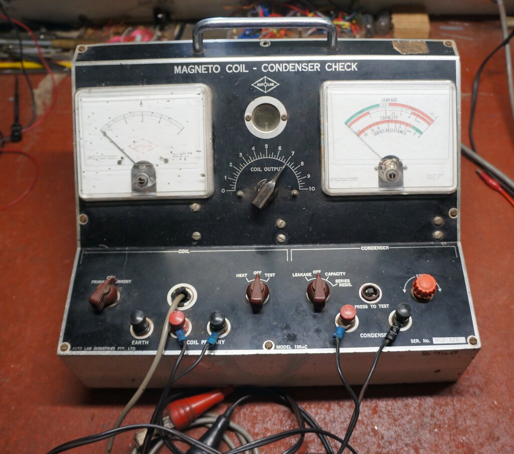
This tester came to me through a fellow Model T club member in the mid 2000's. The Auto-Lab 196AC was made by Vane Electrical Instruments in Sydney. I've described their 453 tester previously.
This one differs in that the 196AC is mains powered. The coil testing functions are done in the same way as the battery operated instrument. However, the 196AC is a bit more advanced, in that coil current is adjustable. The capacitance testing functions are somewhat more revealing also. With the 453 all that is available is a neon indicator for capacitor leakage. The 196AC shows leakage, capacitance value, and series resistance, all on a meter.No doubt the display of the larger two meter instrument in a garage gave an air of sophistication and competency. In reality, the tests are quite basic and hardly precision, but quite adequate for what is required in a practical sense. Construction, both mechanically, and electrically, looks adequate for the garage environment.
This particular unit was made in late 1971, judging from the date stamps on many of the components. As such, it contains the last generation of Australian made components. I did not feel the need to replace any components. The resistors were of a type which are quite stable, except for the 100 ohm - a carbon IRC type which is always suspect. However, it tested perfectly. The .27uF capacitors are UCC "Di-Pol" types which are metalised polyester. These are not to be confused with the similar looking UCC "Hi-Qual" types, which are paper and usually leaky. There was one waxed dipped paper type; the .01uF connected to the 6V6 plate. Given its location, it would not be problematic if slightly leaky.
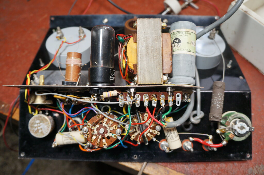
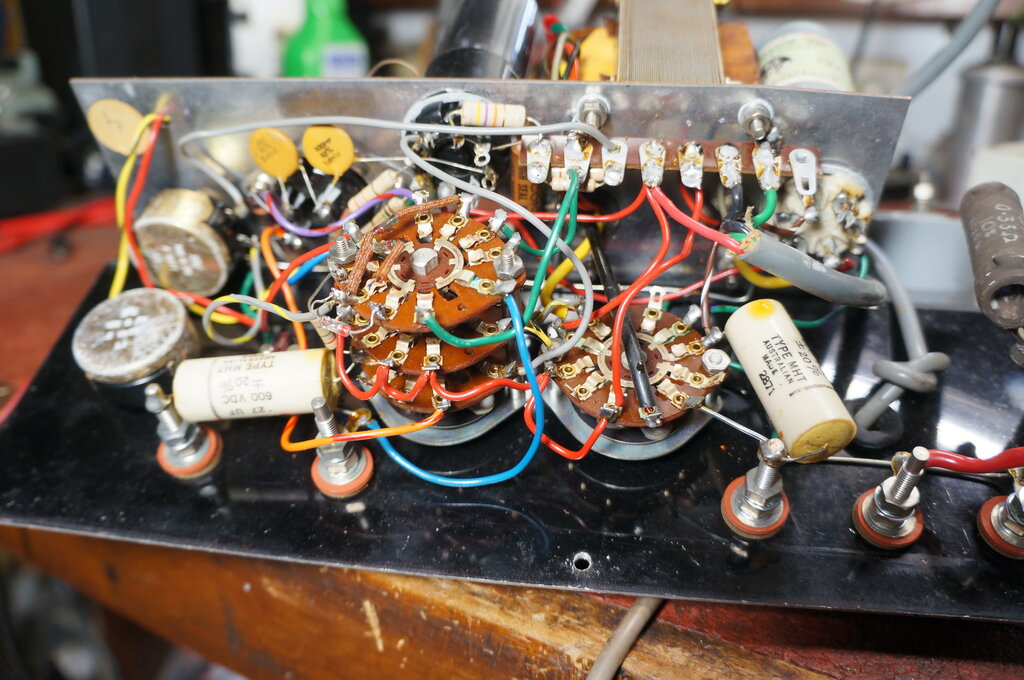
Inside the 196AC tester.
This instrument has an appearance of being
made in a mass production backyard workshop, as does the 453 tester. For
example, the chassis has been bent so the vibrator could be fitted in -
someone didn't allow enough distance from the power transformer. The long
bare wire from the current meter to the .33R resistor is a bit dubious,
as well as being simply screwed under the meter terminal nut, without a
solder lug.
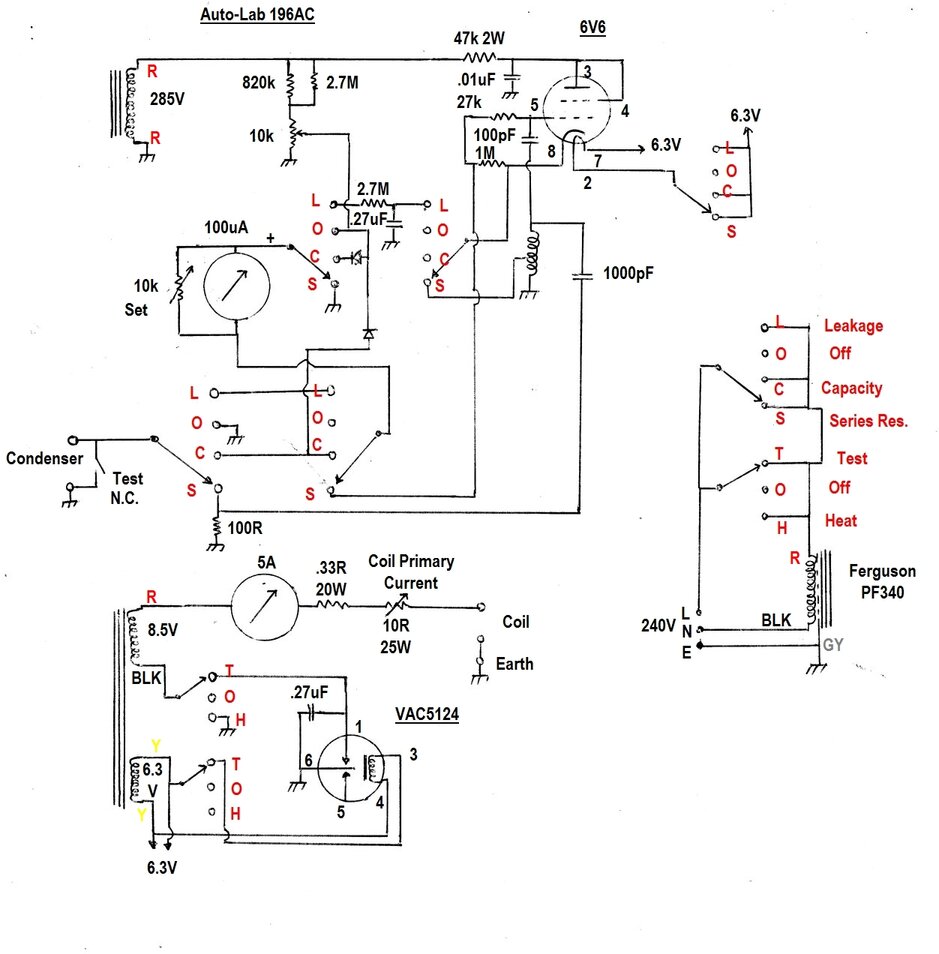
Complete circuit of the tester.
Power Supply.
The entire unit is fed from a Ferguson
PF340 power transformer. This is specially wound model which does not appear
in their catalog. The primary is the usual 240V, and also includes an electrostatic
shield which is earthed. Three secondaries are provided. A 285V winding
powers the three capacitor tests; leakage, series resistance, and capacity.
An 8.5V winding powers the ignition coil under test, and the 6.3V winding
supplies the vibrator coil and 6V6 valve heater.
Note that the 6.3V winding is floating.
This prevents breakdown between the 6V6 heater and cathode when the leakage
test is selected. In this mode, the cathode is around 337V above earth,
and the heater to cathode voltage rating (100V) would otherwise be exceeded.
The mains supply is switched to the transformer
primary when any one of the tests are selected. The 6V6 heater is brought
into operation only when the capacitor tests are selected.
Coil Tests.
The ignition coil under test is powered
from the 8.5V supply through a 10R 25W rheostat which adjusts its primary
current. An additional .33R 20W resistor sets the minimum resistance, and
thus the maximum current. Current is shown on a 5A AC ammeter.
The earth return of the coil is connected
to earth for the heat test, and through the vibrator contacts when testing
the operation of the coil. The heat test simply feeds the coil primary
with continuous current to cause it to warm up. This can indicate thermally
sensitive faults such as open circuits or breakdowns only when hot.
For testing the operation of the coil, the vibrator simulates the ignition points normally used. The .27uF across the vibrator contacts simulates the usual ignition condenser. High voltage output from the coil feeds an adjustable spark gap on the tester. The wider the gap, the higher the voltage required to cause it to breakdown. This gives a crude indication of output voltage.
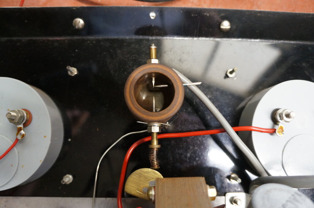
Spark gap. Note the semi-circle shaped cam which adjusts the gap.
It is assumed that the instrument is designed to test both 6 and 12V coils. Provided the vibrator contacts make at the peak of the mains cycle, the coil will actually be supplied with around 12V. (The peak of 8.5V rms is 12V). 6V coils can be tested simply by adjusting the rheostat to a suitable current.
I would have liked overload protection to be present. If the coil is short circuited, the maximum theoretical current that could flow would be about 26A.
The Vibrator.
The Oak VAC5124 is an unusual type which
was made for applications such as this. Although constructed like a normal
radio vibrator, the drive coil is fed with AC. There are no drive coil
contacts. Thus, reed swing is synchronised to the 50c/s mains. While two
sets of contacts are provided as per a radio vibrator, only one set are
used here; i.e. the vibrator operates in half wave.
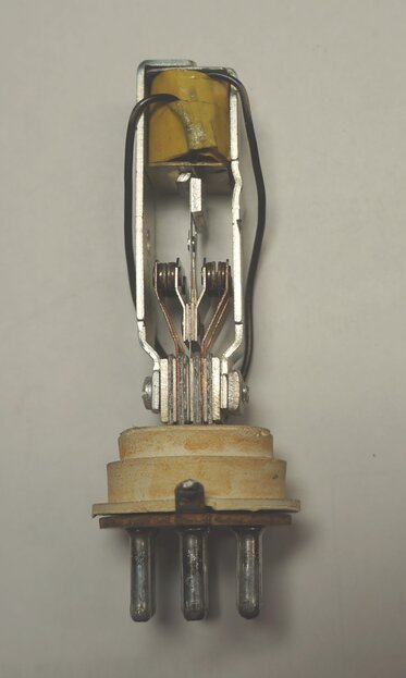
Inside the VAC5124. Note the two coil wires, and the absence of
a coil contact.
The VAC5124 is not interchangeable with the radio type V5124 despite the '5124' in the type numbers. More on this vibrator is described here.
Capacitance Test.
For the capacitance test, the value is
determined by measuring the reactance of the capacitor at 50 cycles. For
this application, reactance can be thought of as AC resistance. In the
case of a capacitor, the reactance decreases as the frequency increases,
and vice versa.
By that same logic, if the frequency is
fixed, the reactance increases as the capacitor value decreases, and vice
versa.
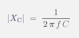
Formula for capacitive reactance. Frequency (f ) is in cycles per
second, and C is capacitance in farads. X is the reactance in ohms.
In its most simple form, a capacitance tester could simply consist of a 50 cycle AC supply fed into the capacitor through an AC ammeter. As the capacitance increases, so does the current. The meter can therefore be calibrated in capacitance; pF for small capacitors, and uF for larger ones.
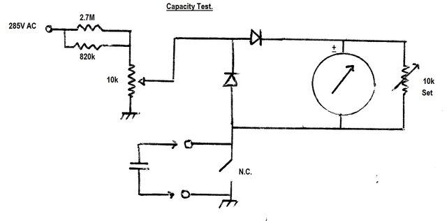
Basic capacitance testing circuit.
In this circuit, the 100uA meter is made to read AC by the addition of two diodes. It's a circuit commonly seen in analog multimeters. AC supply is about 3V, which is tapped off the 10k calibration pot. This is fed from the 285V winding of the transformer through a resistance consisting of an 820k and 2.7M in parallel. The capacitor under test completes the circuit back to the 3V AC source, when the Test switch is opened.
In use, the 10k Set pot adjusts the meter sensitivity for full scale deflection on the meter. When the Test switch is opened, the meter deflection will be less than full scale, depending on the capacitor's reactance. The normally closed Test switch serves two purposes; 1) to set the meter to full scale, and 2), to make sure the capacitor is discharged when it is connected to the test terminals. A charged capacitor could damage the meter and/or diodes.
The meter is fed with half wave rectified AC from the series diode, which conducts on the positive half of the cycle. The shunt diode conducts on the negative half cycle. This diode might seem superfluous since it does not rectify any of the meter current. However, if it was not there, the capacitor would charge up to 3V DC and draw no current. The shunt diode ensures the meter draws current on both half cycles, and the capacitor sees only AC.
Leakage Test.
Testing for leakage is done simply by
passing DC through the capacitor and into the meter. Ideally, the capacitor
will simply charge up and draw no current. It should then appear as an
open circuit. Thus, there will be no reading on the meter.
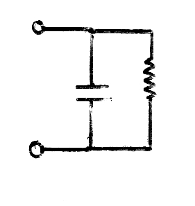
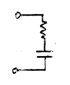
Equivalent circuit of a leaky capacitor.
If the capacitor is leaky, it will present
a DC resistance across its terminals. This not only causes losses in the
circuit in which it is used, but can upset the DC conditions of the circuit,
so that it malfunctions and/or is damaged. For testing leakage, the highest
possible voltage within the capacitor's rating should be used, since leakage
is often voltage dependent.
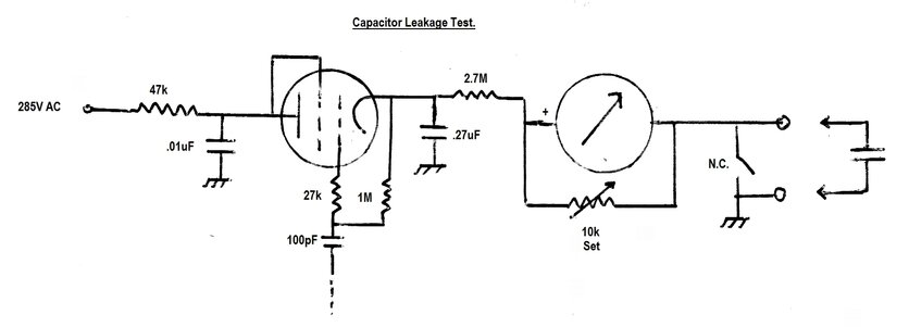
Simplified leakage testing circuit.
In this circuit, the 6V6 operates as a
half wave rectifier fed from the 285V AC supply. The connection of the
6V6 in this mode is such that it functions as a diode. The 27k and
1M resistors connected between the 6V6 grid and cathode don't actually
perform any function here since there is no current flow. They merely provide
a connection between grid and cathode. A piece of wire would serve the
same purpose. The 100pF grid capacitor also serves no purpose, and at 50
cycles its reactance is too high to have any effect. It appears essentially
as an open circuit.
The 47k and .01uF in the plate circuit
also don't serve any useful purpose. The current draw is so low that insignificant
voltage is dropped across the 47k, and similarly the .01uF has such a high
reactance at 50 cycles that it might as well not be there. However, the
47k will prevent any damage in case either the .01uF or .27uF breaks down.
All theses seemingly superfluous components are used for the series resistance
test, and it simplifies the switching by leaving them in.
From the cathode, the DC (around 337V) is filtered by the .27uF capacitor and applied to the meter through the 2.7M resistor. The 10k shunt pot is adjusted for full scale deflection on the meter. When the Test switch is opened, the capacitor will ideally charge up and draw no current. Thus the meter will not show any reading. If the capacitor is leaky, current will be drawn through the meter. The meter scale is calibrated in the rather arbitrary terms, "Good", "Fair", and "Leak". The "Fair" indication corresponds to around 3.3M of leakage resistance.
Series Resistance Test.
Practical capacitors exhibit a series
resistance. The higher this is, the less efficient is the capacitor, since
some of the current flowing through it is dissipated as heat. The better
the capacitor, the lower the series resistance will be. In the modern day,
a popular test instrument is used to find the ESR (Equivalent Series Resistance)
of electrolytic capacitors. Filter and bypass capacitors become ineffective
when their ESR becomes too high.
Capacitors have a series resistance.
In this tester, a rather novel circuit
is used to determine series resistance. All the components we saw around
the 6V6 in the previous circuit now come into use.
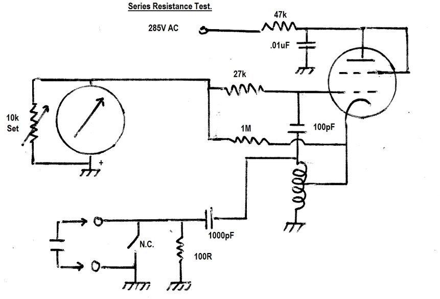
Circuit essentially functions as a Q meter.
The circuit is based around a Hartley oscillator comprising of the tapped RF coil, and the 6V6 which is connected as a triode. It oscillates at around 430kc/s. This frequency is determined by the inductance of the coil, and the 1000pF capacitor which is connected across it.
The 100pF and 27k are the usual grid leak
components, which supply the necessary grid bias to the 6V6. The 100pF
couples the high frequency AC from the coil into the grid. As the voltage
goes positive, grid current flows, causing the 100pF to charge. The grid
functions as a diode plate. When the voltage goes negative, it takes the
grid negative by this voltage, to which is added that across the 100pF.
Thus, the grid goes negative by about twice the voltage. The 27k provides
a discharge path for the 100pF during the negative part of the cycle. As
such, the voltage developed across it is also negative.
In this circuit, the negative current
flowing through the 27k is returned to earth through the meter, which shows
grid current.
The amount of grid current will depend
how active the oscillation is. It can be imagined therefore, if there were
losses in the tuned circuit, the grid current would drop.
Tuned circuits have a certain "Q". Q is the quality factor. The more resistance there is in the tuned circuit, the lower the Q. This resistance could be the DC resistance of the coil, and/or series resistance, or leakage in the tuning capacitor. Sometimes tuned circuits have a physical resistor added to obtain a specific Q.
In this circuit, the point of interest is the 1000pF tuning capacitor. Note that normally it is connected directly across the coil. In this mode, oscillation is the strongest possible. If a perfect capacitor is connected across the test terminals, and the switch is opened, nothing will change. A typical ignition capacitor is around .2uF, which is many times larger than the 1000pF (.001uF). Thus, the tuned circuit sees only an insignificant change of capacitance.
Now, if the capacitor under test should have too much series resistance, this will be effectively in series with the 1000pF, and the oscillation level will drop. Note that the frequency used is so high (430kc/s as against 50c/s), that any capacitor in the intended testing range will appear as a virtual short circuit (less any series resistance). This is why this circuit is not influenced by the capacitor value, and only shows series resistance.
The function of the other components will now be described. If this test is performed without any capacitor connected to the test terminals, the series resistance will be that of the 100R resistor, and the circuit will stop oscillating. Similarly, if the capacitor is open circuit or has a very high series resistance, the oscillation will also stop. When this happens, the 6V6 has no bias and draws maximum current. This would be damaging not only to the 6V6, but also the power transformer. Therefore, the 47k 2W resistor is included to limit the plate current. Even under the worst possible conditions, the maximum current would be only 6mA. Because the 6V6 plate is live at RF, it needs to be bypassed to earth, hence the .01uF. If not bypassed, too much RF would be lost across the 47k and oscillation might be weak or non-existent.
The 1M resistor serves no purpose here.
It maintains continuity between grid and cathode when the 6V6 is connected
as a diode for the leakage test. When performing the series resistance
test, it is effectively in parallel with the 27k.
The 100R resistor defines the maximum
series resistance the circuit can see. Any series resistance in the capacitor
under test is effectively in parallel with the 100 ohm. This resistor also
largely isolates the tuned circuit from the outside world.
Have the astute readers noticed something else yet? Since the oscillator supply is sinusoidal AC, that means oscillation occurs only on every positive half cycle. A rectifier and filter is not needed, since the meter only needs to show the average value.
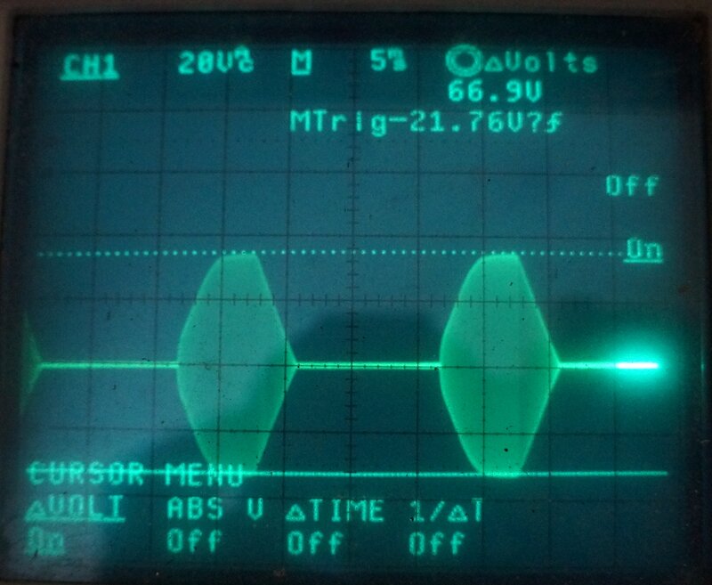
Waveform across oscillator coil. There is a 430kc/s burst every
20ms.
Multi pole rotary switches always make circuit tracing difficult.
Since I'd had an enquiry about the vibrator
from a reader, I first examined that. This is when I quickly learned it
was not related to the V5124 radio type, since the coil connections were
not the same.
It looked as though it may have been opened
before, but whoever did so did a good job of soldering the earth tag back.
As it turned out, I would have to open it anyway. The contacts were covered
in the usual insulating film which builds up from years of disuse.
Once cleaned, it was then found that one
set of pull contacts were touching. It looked like someone might
have been there before with long nose pliers. I readjusted the contacts
and the vibrator tested OK.
Meters.
Both meter zeros were way off, with the
needles far to the left. The actual zero adjustment on the meter covers
was not sufficient, and for the AC ammeter, the plastic pin had broken
off anyway.
The meter covers are simply clipped on,
and removing them allowed the zeros to be set inside. Even though it was
possible to zero both meters, it was a curious thing why the adjustment
required was much more than available from the front panel. Possibly the
movements had become magnetised. I had also noticed the meters were very
position sensitive. They must be upright in their normal position for the
correct reading.
Comparing the AC ammeter against an AVO 8, the ammeter was reading slightly high, with the discrepancy increasing with current. With the ammeter showing 4A, the AVO showed 3.6A. For its purpose, the accuracy is adequate.
Coil Testing.
Next thing was to try the coil testing
function, and this worked exactly as expected.
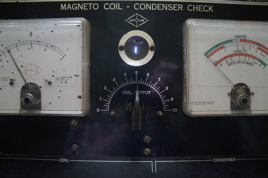
Spark gap shows coil output.
I wasn't ready to try the capacitor tests,
since with no instructions, I didn't know what I was dealing with and what
to expect. So, at this point I traced out the circuit.
Now, with an understanding of what should
happen, I began testing.
Leakage Test.
After allowing for the 6V6 to warm up,
the leakage test worked as it should. For the "Fair" reading (mid scale),
the resistance was 3.3M.
Capacitance Test.
This was completely inoperative. The circuit
is so simple, there's only a couple of likely faults. First to check was
AC supply, and about 3V was present at the calibration pot wiper (when
the Test switch is opened). This should be more than enough to obtain meter
deflection. The next likely thing was the diodes, and sure enough one of
them was open circuit. These are, not surprisingly, germanium types, given
the age of the instrument. Replacing the faulty diode restored operation.
It's possible someone had connected a charged capacitor after pressing
the Test switch. However, I have seen germanium diodes going open circuit
just from old age.
The indicated capacitance value was surprisingly
accurate, except for values at the lower end of the scale. For example,
a .1uF capacitor indicated slightly less - although the scale is not calibrated
for values less than this, it was probably indicating about .08uF. Again
it needs to be emphasised, this is not a laboratory grade instrument, and
it is accurate enough for its purpose.
Quite possibly, the replaced diode had
affected the calibration. I did experiment with recalibrating it, but without
any improvement.
Series Resistance Test.
This functioned, although the readings
were quite inaccurate, with the meter showing much less than it should.
For example, 15 ohms of known series resistance measured about 3 ohms.
Apart from the initial setting of the meter to full scale deflection, there
is no method of calibration.
Set Control.
For all the capacitor tests, the Set pot
was difficult to adjust. Although the pot is a wirewound type, connection
between the wiper and resistance track is not always perfect. This, and
that the ideal setting is very close to the low resistance end, makes the
pot difficult to adjust. It would seem that the ideal resistance should
be a lot less than 10k. Either that, or use a less sensitive meter. In
fact, testing the sensitivity of the 100uA meter showed FSD at 67uA. On
that basis, the response of the meter seems quite linear, with about 33uA
to bring it to mid scale.
Instructions.
Not surprisingly, no literature came with
the tester. However, from tracing out the circuit, it was fairly obvious
how it should be used. I did find mention of the 196AC on a forum here
https://www.smokstak.com/forum/threads/autolab-tester.168872/
Auto-Lab also produced simpler instruments,
in which the condenser and coil testers were separate instruments. These
were shown on the forum, and conveniently, the instructions were on the
front panel.
Since forum images tend to have a habit
of disappearing after time, I reproduce some of them here.
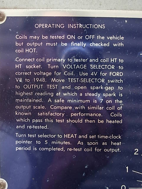
Coil Tester instructions.
The coil tester shown is a "Coil Check" model 205. It is not exactly the same as the 196AC, but these instructions explain the spark gap setting, and the use of the heat test function. The amount of current for the heat test is fixed, and not known. However, the presence of a headlight bulb in the 205 means it's probably like the 453, and puts through about 4A at 12V.
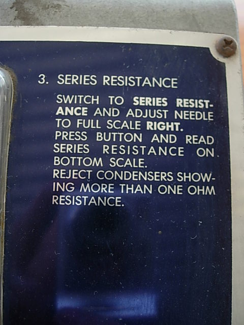
Condenser Tester Instructions.
The condenser tester, "Condenser Check", model 215, appears identical as far as its circuit is concerned, except the 47k 2W resistor in the 196AC (in series with the 6V6 plate) is 51k 1W. The difference would be insignificant, since both values are within 10% tolerance.