The valve heaters are now run at their correct voltage.
The valve heaters are now run at their correct voltage.
Introduction.
First, refer to the original article if
you have not done so, here.
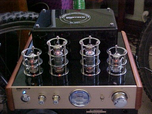
Basically, this amplifier was sold by Jaycar in the last quarter of 2008.
However, it turned out to be a fake in that the amplifier was in fact solid
state, using LM1875 power amp IC's and some 4558 op amps. The valves were
in the low level signal path. Despite one pentode (6P15) and a twin triode
(6N1) being present, one half of the twin triodes was not connected to
anything, and the remaining triode was connected in parallel to the pentode
to form a single triode. In effect, we see the bling factor, for out of
the three valve sections per channel, only one would have been required.
Furthermore, to add to the bling factor was the valve heaters were run
at around 9V, thus making them appear somewhat brighter. Jaycar quickly
dropped the price and withdrew the amplifier from the next catalog once
it purchasers started complaining. In actual fact, Jaycar had not actually
examined the amplifier before purchasing and advertising them.
Another Amplifier.
I had toyed with converting my original
amplifier to be the real deal, but having paid $299 for a fake, I felt
rather ripped off, so returned it. In early 2011, I acquired another one
for $30. And so, I decided to rip out the solid state nonsense of this
one and make it into a proper valve amplifier. For those who wish to keep
theirs 'fake', I did at least analyse the heater circuit and show how to
correct the heater voltages as described in the original article. As I
discovered, the higher heater voltage had actually damaged the two 6P15
pentodes in this second hand unit.
Making the conversion.
Looking back on it now, there was actually
quite a lot of work involved, but the end result was worth it. First thing
was to gut the amplifier, except for the switches, VU meter, and terminals.
The pots, being 50K were too low for valve circuitry so had to go. The
transformer enclosure turned out to be made of MDF, and the screws don't
go in very far. Therefore, don't pick the amp up this way, as convenient
as it is to do so.
Power Transformer.
With a low turns per volt ratio (4.5 turns/volt),
the existing toroid looked good for rewinding. First thing was to remove
the existing 32V CT secondary, leaving the 240V primary as is. For the
250V B+ supply, the easiest way was to wind a 120V secondary and use a
voltage doubling rectifier. This saves winding time! Winding a toroid isn't
as difficult as it seems. By winding on the required length of wire on
a small reel, it can be threaded through the core of the toroid and wound
around. I didn't count the turns, but in the end there was a bit over one
layer. This resulted in 124V off load, and about 121V when loaded with
a 40W lamp.
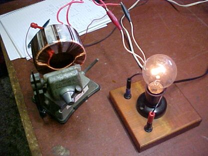
New secondary under test, powering a 40W lamp. Voltage under load
was about 121V.
Next, was to deal with the heater winding.
Here, I simply re used the original wire, but of course with less turns.
Unfortunately, this secondary ran warmer than I would have liked when powering
all four valve heaters. So, I simply wound on another, with the idea of
each 6.3V secondary powering two valves; i.e. a 12.6V CT secondary. This
spreads the load and I get to use the original wire gauge. Regulation is
good. In fact, compared to toroids, conventional laminated transformers
are just primitive with their low efficiency, poor regulation, and hum
radiation. The original toroid is rated at about 60VA which would just
be sufficient.
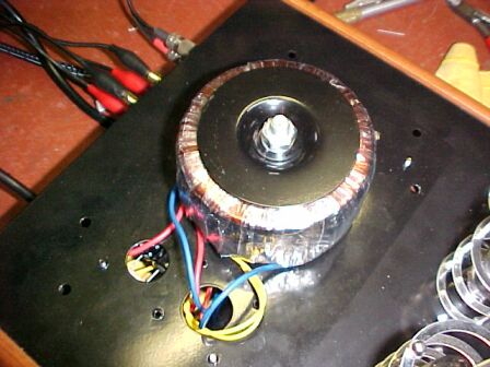
There's a few more wires coming out of the rewound transformer.
The yellow wires are 120V, the blue and orange (not visible) are 12.6VCT,
and the red are the 240V primary.
The Circuit.
I chose a completely conventional 1960's
style circuit. My idea was to use the twin triode around a Baxandall tone
circuit, and the pentode as a normal class A output providing a few watts.
Personally, I am not fond of tone controls, but the front panel indicated
they had to stay! As I was limited to 500K pots (those were the only high
value types I could get that were physically the same as the original),
I found a suitable Baxandall circuit using this value. The tone control
circuit I used came from the Hong Kong magazine, "Radio World", from August
1967.
Preliminary tests with the 6P15 pentodes
in an output stage resulted in poor power output; about 1.5W. It turned
out the cathode current was around 22 to 29mA with both valves; a bit short
of the 41mA specified. Sure enough, putting them on the AVO valve tester
showed both valves were weak. No doubt this was due to the high heater
voltage they had been subjected to in their previous life. So, out with
a set of 6BQ5/EL84 valves and all was well. These are direct equivalents
to their Chinese/Russian counterparts.
As far as the speaker transformers were
concerned, I used Rola type E41's which are 7K to 15 ohms. This is the
largest type I had that would fit under the chassis. As most speakers are
8 ohms, it meant unwinding the secondary to produce an 8 ohm tapping, and
then winding the remainder back on in case I ever wanted to use 15 or 16
ohm speakers.
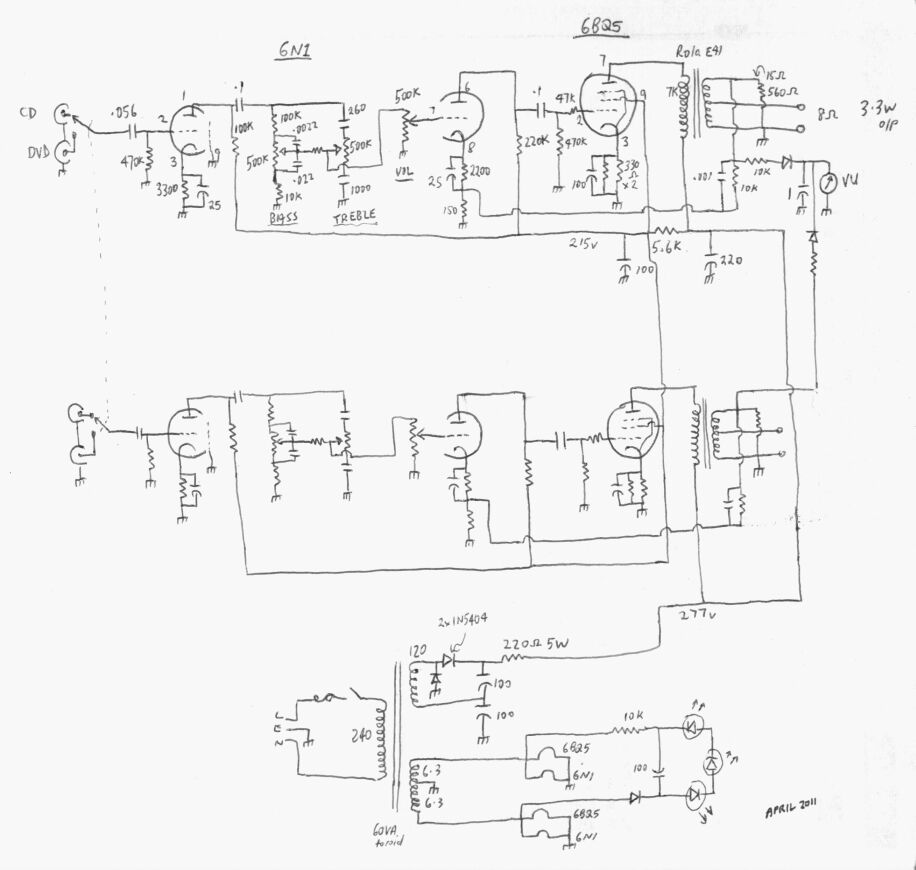
Circuit of the new amplifier. The unmarked resistor between the
tone pot wipers is 100K.
Turning now to the circuit diagram, the
input is fed to the first half of the 6N1 which provides gain to overcome
the attenuation of the Baxandall circuit. After leaving the tone controls,
the signal is then passed through the volume control into a conventional
triode pentode stage. One could obviously use more common twin triodes
such as 12AX7, 12AU7, etc., keeping in mind the differing gains available,
and that strictly speaking the cathode bias resistors should be set to
provide around 120V volts on the plates.
The 6BQ5 conditions are set for a 7K plate
load. Measured output per channel is 3.3W.
This could have been improved on with
larger speaker transformers, but there just isn't the room. Nevertheless,
with both channels going, it makes lots of noise! Negative feedback is
applied to the cathode of the second triode; about 6dB is used here. This
improves distortion and frequency response. The .001uF across the 10K feedback
resistor corrects for the phase shift introduced by the transformer and
may need to be changed if other transformers were used. Seeing as there
was a VU meter to be fed, I decided the best way would be to rectify the
signal from the 15 ohm tap. This worked well, with a 10K series resistor
to provide a 0dB reading at full output before clipping. As we have only
one meter, both channels are simply fed into it via their separate rectifiers.
Some may wonder about the 560R across the speaker transformer secondary.
It turned out that one channel would supersonically oscillate with no speaker
connected. No doubt this was due to some layout issue, but a tiny amount
of damping was all that was required to make it completely stable.
Power Supply.
This is quite standard, with the 120V
being doubled by the rectifier circuit. Basically, it functions as two
half wave rectifiers; one working on the negative cycle, and the other
on the positive. The two 170VDC 'supplies' are connected in series, producing
340V with no load. Simple resistive filtering is used which works well.
Given the large capacitor values, there is no audible hum.
The 6.3V windings feed the valve heaters
in the usual way. There are also three blue led's; two for meter illumination,
and one for power on. Rather than stuff around with running them as they
were originally, each with their own resistor, I decided to put them all
in series which not only made for neater wiring, but meant only one dropping
resistor was required. They are fed from the 12.6V via a half wave rectifier.
The brightness of the power led was way
too bright with the original amplifier; in fact it was painful to look
at, so I've reduced the current accordingly, without reducing the meter
illumination drastically.
The transformer is running at full ratings,
and given the poor ventilation of the enclosure, I included a 70 degree
C thermal cutout. This was mounted on the top transformer mounting washer.
It has tripped on warm days when the amplifier has been running for several
hours, so I am considering re-using the small 12V fan that was originally
under the chassis.
Constructional points.
To adapt the original chassis meant that
a bit of metal work was involved. The original valve sockets were mounted
on a PCB. While ordinary chassis mount valve sockets could have been attached
to the amplifier chassis, it left the question of where to mount the tagstrips,
without extra screws appearing and disfiguring the appearance. Also, the
'cages' around the valves would require the lowest 'ring' to be omitted
to clear the valve socket screws. So, the ideal way was to make a sub chassis
and mount it like the original PCB. This worked well, although fiddly to
mount as it's secured with all 12 of the valve 'cage' screws. Small spacers
give clearance between the two chassis.
I was able to re use the tone control
PCB as the original used something very similar to a Baxandall circuit.
I simply replaced the pots and other components for the new circuit. The
volume control and input switch PCB's were directly usable as is. Unfortunately,
the original amplifier did not use shielded cable. Obviously they thought
they'd get away with it as the impedance was much lower. But, with a valve
circuit and 500K maximum impedance, shielding was essential. This meant
lost of shielded wire running about. It's messy to work with and the terminations
never look tidy, but it does the job. The layout didn't help either. It
would have been nicer to have the volume control adjacent to the tone controls.
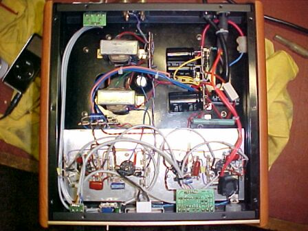
Under the converted amplifier. The circuitry is largely assembled
on an aluminium sub chassis which takes place of the original PCB. Speaker
transformers are at top left, while power supply components are at top
right.
Powering Up.
First thing to do was to select the two
filtering resistors to set the 6BQ5 plate voltage to 250 and the screen
to 210V. Note that these voltages are with respect to cathode, and that
the voltage drop across the speaker transformer is taken into account.
The amplifier performed very well straight away, but I detected a hum in
the left channel. It didn't take long to realise it was the mains switch
being so close to the grid pin of the 6N1. A piece of tinplate soldered
to the valve socket centre shield, covering the grid pin fixed this one.
As mentioned before, I also discovered the right channel oscillating ultrasonically,
and again this was an easy fix.
The amplifier could not be considered
true Hi Fi, mainly because of the speaker transformers. It could be best
described as that of a good quality radiogram. But, a good set of speakers
makes all the difference, and listening to the new amplifier is highly
addictive!