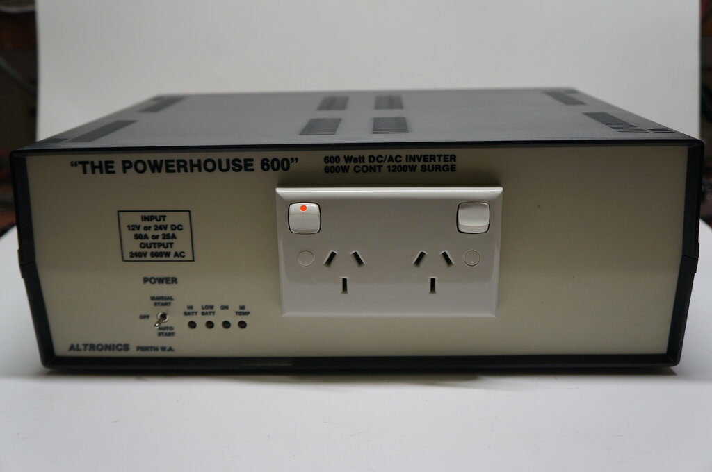
The front panel labelling is misleading. The inverter requires wiring and component modifications to select between 12V and 24V input. It is not automatic as might be implied.
The front panel labelling is misleading. The inverter requires wiring
and component modifications to select between 12V and 24V input. It is
not automatic as might be implied.
This inverter was available as a kit or a made up version from the Australian electronics parts retailer, Altronics. It was developed in 1996, but the origins go way back to the Electronics Australia 300W inverter from February 1979, which was their first solid state design. For readers outside of Australasia, "Electronics Australia" was one of two electronics magazines which existed at the time. Electronics Australia subsequently produced several more inverters along this design, each being an improvement over its predecessor. One such design is this one.

From the Altronics 1997 catalog.
Altronics produced a few more designs themselves. The two versions shown in the ad above, along with a 300W model, were not described in Electronics Australia, probably because the magazine was by this time in the stages of being 'dumbed down' prior to its death in 2001. These two inverters were an improvement on the December 1987 and February 1992 designs, incorporating a microprocessor and "phase correction" circuitry.
Chronology of Electronics Australia Solid State Inverters.
Circuit Design.
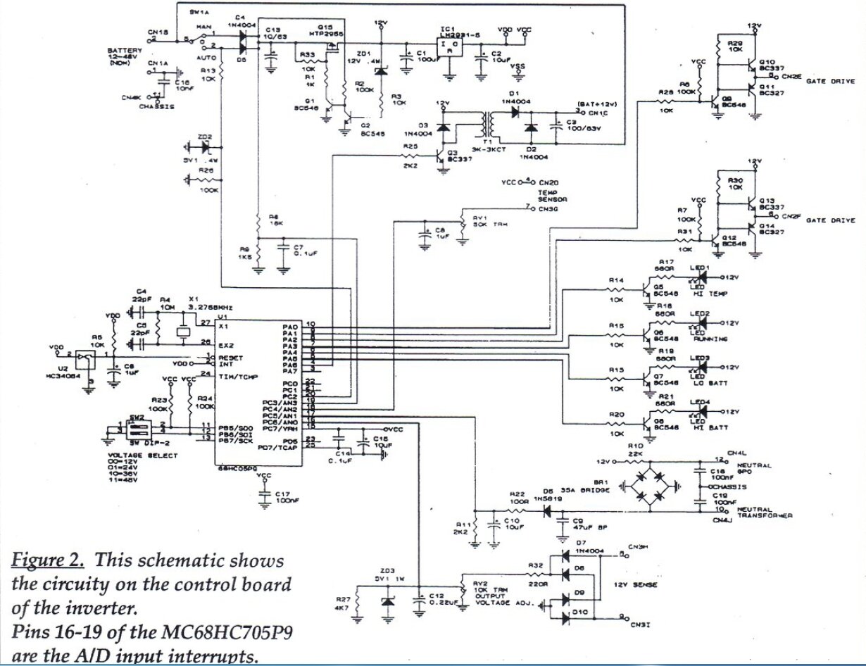
Circuit of the control board.
The heart of the circuit is an MC68HCO5P9
microprocessor which replaces all the CMOS IC's and op-amps used previously.
The microprocessor generates the anti-phase 50Hz drive signals for the
switching MOSFETs, provides the voltage regulation circuitry, and incorporates
the auto-start and under/over voltage detection circuitry. The timebase
is crystal controlled, unlike some previous models.
Over temperature sensing is provided,
as with all the previous 300W/600W/1200W designs. However, electronic current
sensing for overload protection is not used. This is achieved simply by
using a circuit breaker.
Depending on the DIP switch settings,
choice of transorbs, and the transformer connections, the same circuit
caters for both 12V and 24V operation. The 1200W inverter is the same design,
except has double the number of switching MOSFETs, and of course a larger
transformer.
Regulation.
The inverter is a modified square wave
design. Regulation is achieved by adjusting the pulse width. Feedback is
provided by a 12V winding on the power transformer - the voltage here being
proportional to the voltage induced in the 240V output winding.
The feedback voltage is rectified and
adjusted by RV2, prior to being fed into pin 16 of the micro. It's compared
to an internal voltage reference, and if the output voltage low, pulse
width (duty cycle) is increased to compensate, and vice versa.
Auto-Start.
The auto-start circuit is based on that
used since the September 1985 design, based on a reader submitted circuit
in the February 1981 "Circuit and Design Ideas" section of EA. A bridge
rectifier is connected between the load and transformer secondary. The
DC output of the rectifier is short circuited, which results in 1.4Vp-p
across its AC terminals when the inverter is operating, and a with a load
drawing current. At the same time, a small current is fed from the 12V
battery supply into one of the AC terminals of the rectifier, superimposing
0.7V on it. When the load is connected, the DC path allows this 0.7V to
come back into the other AC terminal which is used to sense whether the
inverter should start.
In more detail, R10 (22k) feeds 545uA
into the upper right diode of the bridge. When the load connected has a
DC path, 0.7V appears at C9 (47uF). Because there's AC present once the
inverter starts, D6 rectifies this, and charges C10. Once a voltage appears
across C10, the micro starts the inverter, by generating the drive voltages
for the switching MOSFETs. C9 is used to prevent stray capacitance in connecting
leads from causing the auto-start to run. This might happen because with
enough capacitance between cable conductors, enough current will keep flowing
to keep the auto-start circuit activated. C9 shunts the AC to earth, and
ensures only DC coming back from the load will activate the auto-start.
24V supply.
Described later for the "phase correction"
circuitry, a supply of around 12V greater than the battery voltage is required.
This is generated by an audio transformer T1. It's fed by a approximately
12Vp-p 1.3kHz square wave. The rectified secondary voltage is connected
in series with the 12V supply so that it adds, producing about 24V.
Over Temperature Sensing.
An LM334Z is mounted on the heatsink,
and if the MOSFETs should run excessively hot, as with too high of a load
connected, the voltage at pin 18 of the micro will rise sufficiently to
cause the micro to shut off the inverter. This can be adjusted by RV1.
5V Supply.
The micro requires a 5V supply which comes
from a low dropout LM2931-5 regulator. There is a pre-regulator based around
Q15 which is a P-channel MOSFET. It provides a 12V input to the 5V regulator
and MOSFET drivers, and is only really required for the 24V version. Basically,
Q15 conducts because of the gate voltage supplied by the 1k (R1) gate resistor.
If the output rises above 12.6V, ZD1 conducts, turning on Q2, thus turning
off Q1 and removing gate voltage to Q15. It can be seen that when the inverter
is run off 12V, Q15 is always saturated.
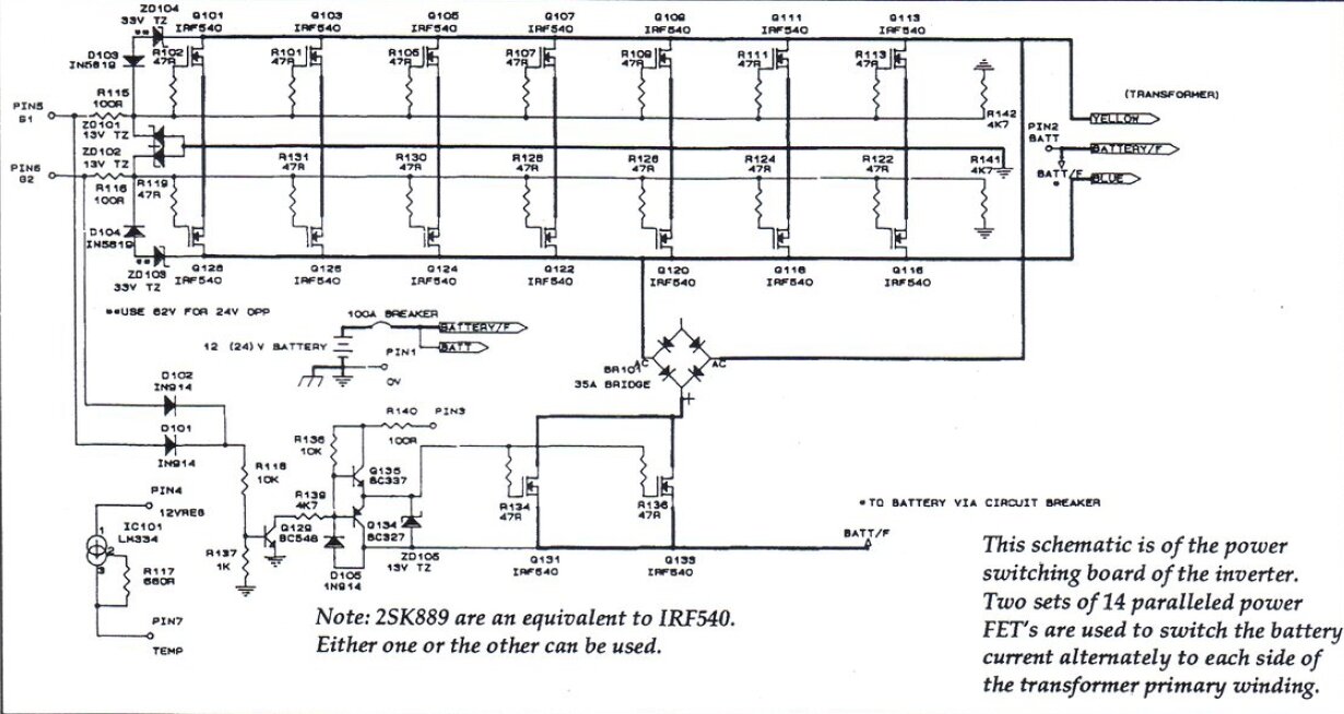
Circuit of the power board.
Transformer Switching.
Since the September 1985 design, all the
high power inverters have used toroidal transformers. These are vastly
more efficient and have better regulation than the conventional E-I laminated
types. They are also lighter.
From the December 1987 designs and onwards,
the transformer has been switched by MOSFETs. These have a lower voltage
drop compared to bipolar transistors, as well as being available in higher
current ratings. Thus, the heatsink runs cooler, and the inverter is more
efficient. Aside from that, MOSFETs are voltage driven, which makes for
simple driving circuitry since no current is required. Bipolar transistors,
on the other hand, require a comparatively considerable base current.
In this inverter, there are parallel sets
of seven IRF540's for each side of the transformer primary. 33V transorbs
conduct if the back EMF becomes excessive, causing the MOSFETs to turn
on, shunting the excess voltage to earth. Because of the gate to source
capacitance and fast switching speed required, the gates are fed from push-pull
emitter follower circuits comprised of Q10/Q11 and Q13/Q14 on the control
board. If the MOSFETs were fed directly from the micro, there's a risk
that the current output would not be enough to overcome the gate capacitance,
which would result in a slower switching speed. The inverter would still
work, but with the slow switching speed would cause the MOSFETs to operate
in their linear mode for longer than desirable. At the high currents at
which this inverter operates, the MOSFETs would run hotter, as well as
cause low efficiency.
Phase Correction.
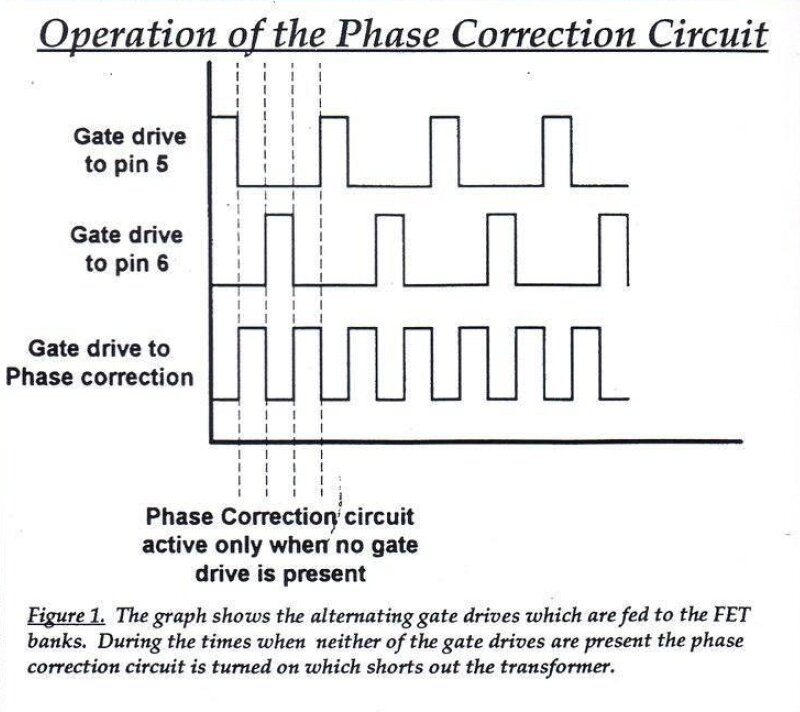
New to the inverter designs is this so
called "Phase Correction Circuit". A more accurate name would be "Active
Back EMF Suppression", since that's what it actually does. Phase correction
infers correcting for the power factor of inductive loads, which this circuit
does not do.
Instead, low power factor loads are simply
run as is, and this circuit suppresses the back EMF caused by their inductive
loading. (Although a capacitive load also causes a low power factor, most
low power factor loads are inductive). To see how this circuit works, note
the bridge rectifier connected to the transformer primary (BR10). Only
two diodes are used, and these connect via a parallel set of MOSFETs, Q131
and Q133, back to the transformer centre-tap. These MOSFETs are driven
by an out of phase voltage derived from the drive voltage, which drives
the main switching MOSFETs. The out of phase signal is derived by Q129.
The upshot of all this is that the transformer primary is short circuited
when the main switching MOSFETs are not conducting. Thus, any back EMF
(which occurs during the off time) is short circuited.
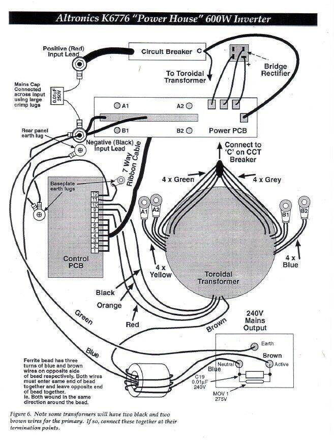
Wiring diagram. The 240V wiring and transformer are not actually
shown on the circuit diagrams.
An attempt is made to filter the 240V output with a toroidal core in the output wiring and a 0.01uF capacitor. A 275V metal oxide varistor is also included to suppress high voltage spikes. The 0.01uF across the 12V input looks doubtful as to its effectiveness.
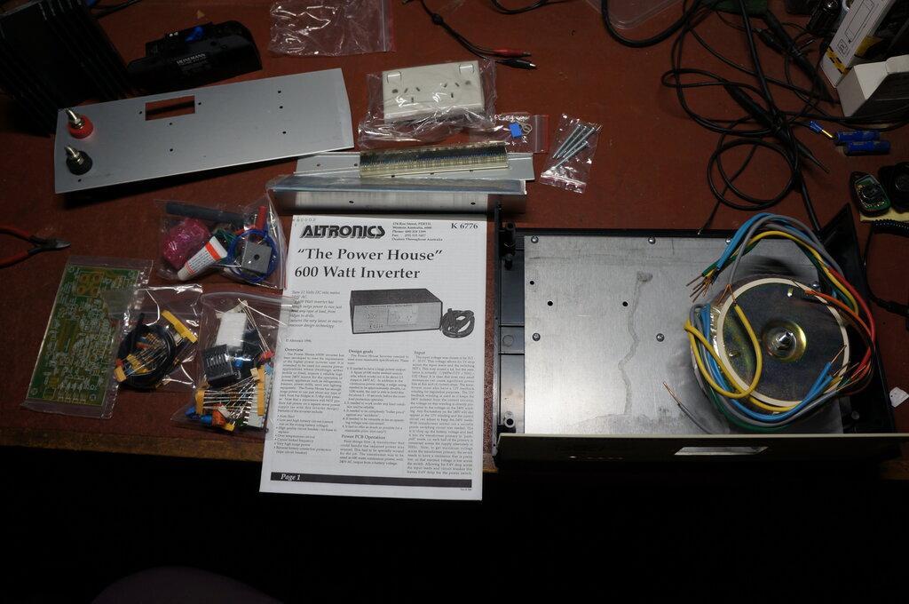
Parts of the kit prior to assembly.
As packaged, the transformer had already
been mounted to the chassis, which in turn was screwed and bolted to the
bottom of the plastic case. This makes sense given that such a weighty
transformer can't be left loose in the box.
The assembly was not particularly difficult,
although missing parts did slow things down. The control board was assembled
first and was straightforward. The PCB calls for three links (actually
zero ohm resistors). However, the parts list shows only two, which is what
was supplied. One of the links was therefore simply a component lead off
cut.
The LEDs and power switch are mounted
on the PCB which then mounts on the chassis with plastic standoffs. The
LEDs did not quite line up with the holes in the front panel, so it was
necessary to bend their leads to the side slightly. Interestingly, the
DIP switch settings on the board show 36V and 48V operation, as well as
for 12V and 24V. Yet, these higher voltage input inverters, if they ever
existed, were never advertised.
The biggest difficulty was with the power board and the MOSFETs. The MOSFETs are meant to be insulated from the heatsink bracket with silicone strips extending the full length. Unfortunately, these were missing, and they are not easily available (i.e. can't just go to Jaycar or Altronics to get them), and ordering on the internet would take a long time (ebay - China), or I'd pay excessive postage (Australia). Over the years, I've collected the silicone insulators from things I've pulled apart and I had sufficient to use. But since each individual MOSFET had to be insulated, since I didn't have the strips, it was difficult to keep the insulators in place while tightening the clamps. Added to this was the PCB was warped because of having to add solder to the MOSFET tracks. In the end, I made up small end brackets to secure the PCB against the heatsink bracket. This worked well, except I broke my 9BA tap twice in threading the holes for the two small brackets. I used a small amount of heatsink compound to secure each silicone insulator behind the MOSFET so that they would stay in position until the clamping strips were secured. Eventually, it all went together OK.
I found the wording describing the wiring between the MOSFET sources and the battery negative terminal hard to follow, and had to read it numerous times to understand it. Part of the confusion is that for each of the two groups of MOSFETs, the source wires are two different lengths. With the high currents that could flow, one wire would carry more current than the other.
The lugs for the transformer primary wires did not fit. The transformer has multiple primary windings, connected in parallel for 12V, or in series for 24V. Problem was that the lugs were too small to accept two of the primary wires. Fortunately, I did have some which fitted. The parts list should have specified yellow lugs, not the blue ones supplied. Incidentally, there were insufficient nuts supplied to connect the transformer lugs to the power board. These are 4mm, which I had, so did not cause a problem.
The next hurdle was the short length of cable from the circuit breaker to the positive battery terminal. Again, the lug was too small and it was impossible to push the conductors into the lug. I had to cut a slot down the body of the lug and spread it apart to get the wire to fit.
Only one earth lug was supplied (and no screws for it, or any of the missing two lugs). Luckily, I've got a good stock of parts, and was able to proceed, wiring the earths up from the back panel, chassis, and power point.
The instructions state (and show) three
turns of the live and neutral wires passing through the ferrite core, prior
to connection to the power point. Not only was this impossible, because
the brown wire from the transformer was simply not long enough, neither
was the piece of blue wire intended for the neutral connection back to
the control board. As such, I could only wind one turn of each through
the core. I don't see it as particularly critical and have not worried
about it.
A minor point is that if the supplied
solder wire was meant to be enough to assemble the kit, it was about a
length too short. I used it all up and was using my own stock by the time
I got to the connections of the transformer lugs.
Supplied with the kit is a cable with battery clips, intended for use when the inverter is used in a portable situation. It appears to be a set of car jumper leads cut in half, so that one set makes up two inverter kits. As with most car jumper leads, the thick (10mm diameter) insulation implies a high current cable, but is usually quite deceiving. In fact, the internal conductor is only 4mm diameter. At 50A, there would have to be significant voltage drop.
With the inverter finally assembled, the micro was plugged into its socket, and the inverter powered up on a 2A current limited power supply. The green LED came on, and the 50Hz buzz could be heard from the transformer. It appeared all was working, and so the output voltage was adjusted with a true RMS meter, and the temperature sensor was calibrated by measuring its voltage against the ambient temperature (the instructions show how to calculate this).
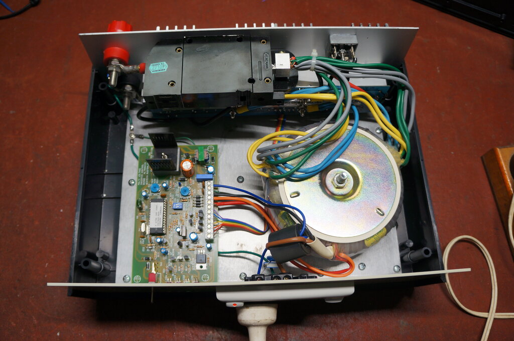
Completed inverter.
No load waveform.
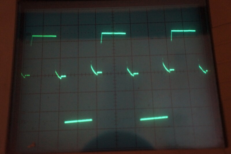
60W resistive load.
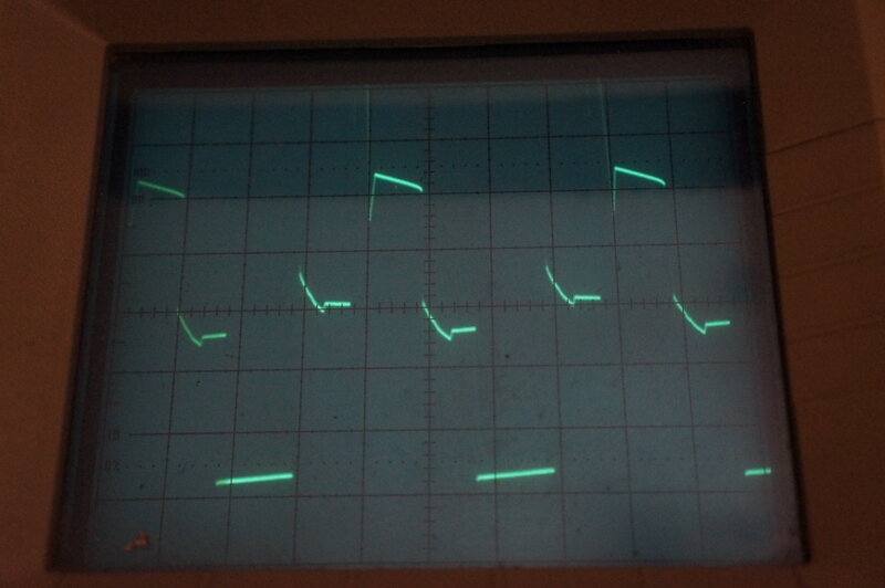
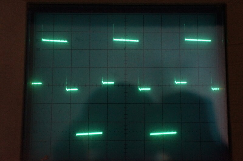
15W fluorescent lamp. Note the short spike at the leading edge.
A VHF receiver was tried and no RFI was
evident. A couple of 15W fluorescent lamps were tried (both without power
factor correction) and the inverter was able to drive them.
A slight wavering of the duty cycle is
evident, with a shimmering visible with incandescent lamps. This appears
to be something to do with the voltage regulation circuitry.
My only criticism of the kit is that for
$535, you'd want all the parts to be present. And, you'd want the lugs
to fit the cables. There seemed to be some stinginess with the hookup wire
supplied. Apart from the blue neutral wire being too short (if the specified
three turns through the toroid were included), there was insufficient length
of the green earth wire. How one was meant to fit three turns of the transformer
secondary wire through the toroid, when it too wasn't long enough, has
me curious. I wouldn't want to be in the position of someone in an isolated
place who had no stock of parts to draw on, should the kit be missing something.
The instructions were a black and white
photocopy, and as a result, the photos of the inverter construction were
almost useless. To be fair, it was produced in the days before cheap colour
printing, but still for the price and complexity of the kit, they should
have provided clear colour photos - or at least photos with a greyscale.
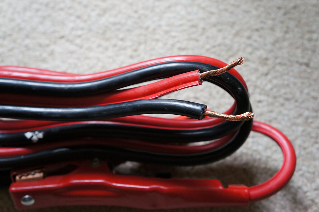
The car jumper leads supplied.
Out of curiosity, I tried the supplied
car jumper lead cable with the inverter connected to a 100Ah AGM battery.
The inverter load was a 550W toaster. Surprisingly, it worked a lot better
than I thought. There was about 0.7V drop between the battery terminals
and the inverter. Since the cable is only about 1.5m long, the short length
would help.
The cable did run slightly warm, but full
240V output was maintained. A couple of 20W fluorescent lamps were then
tested; one being a conventional switch start type, and the other being
a rapid start type. These both worked normally. A medium size bar freezer
also appeared to work normally. Despite the instructions claiming that
a 3/4hp drill press could be powered off the inverter, mine ran for about
two seconds before the circuit breaker tripped.
In summary, the inverter is a good design, and my only reservation would be if the micro failed - it would be necessary to substitute it with conventional circuitry; not difficult, but still tedious.