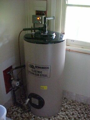
Here resides the Edwards DES125 stainless steel water heater.
Having set up the solar powered electrical system for my house and seen how successful it was, the next step for less dependence on outside services controlled by big business, was to have my water heated by solar.
Learning about water heaters.
Late 1996, when my 15 gallon Zip water
heater tank had corroded to the point of brazing up the pinholes being
a futile exercise, I was forced to replace it. This is when I learned that
most water heaters for sale now are essentially junk. My original tank
was made of cusilman bronze and it had lasted 30 odd years with full mains
pressure applied to it. I'd also lived with copper and copper lined tanks
which were also reliable. Much to my surprise neither cusilman bronze,
or my other choice, copper lined steel (eg. Rheem Coppermatic) heaters
were still being made. Something about water quality the manufacturers
told me...but they could offer me any number of models with glass lined
tanks. No way would I spend money on something which was actually destined
to fail from the first day it held water. For those unfamiliar with the
concept, glass lined tanks are a mild steel (just saying that makes one
think of rust) with vitreous enamel (fancy name for molten glass) sprayed
onto the inside surface, supposedly protecting it from corrosion. Which
it would, except that the steel cylinder expands and contracts as it heats
and cools. As glass is not flexible, minute cracks appear and the tank
is now doomed. To slow down the rate of corrosion, a sacrificial anode
is inserted into the tank. It's made of magnesium and is meant to corrode
instead of the steel. However, most owners of glass lined tanks never check
the anodes, or replace them once corroded away. Also, the corroding magnesium
ends up in the tank and hence the hot water that issues forth. Such tanks
often have words like "Vitreous", "Enamel", "Glass" or that abominable
misspelling by Rheem, "Glas", in their model names. The inside of them,
if you haven't ever seen a cutaway model, is just like an oven baking dish.
If you're unfortunate enough to be stuck with this kind of heater, run
it at the lowest temperature and water supply pressure you can, and check
the sacrificial anode. Edwards and Beasley seem to be the predominate manufacturers
of stainless steel water heaters, so in the meantime it's worth familiarising
yourself with their models, ready for when the time comes.
Most water heaters in Australia are of
the mains pressure type, hence the requirement for a strong tank. To allow
for pressure build up, a TPR (Temperature and Pressure Relief) valve is
fitted. This opens thermostatically at 99 degrees (in case the heating
element doesn't shut off) so that steam doesn't build up causing an explosion.
In addition, should the thermal part of the valve be not functioning, the
valve will open with extreme pressure alone (chosen to be above the pressure
of the water supply).
Once popular until the 1960's when the
Rheem Coppermatics came into vogue, were gravity fed copper tanks, usually
installed inside the roof space. These have an exceptionally good life,
and fed from an open cistern, do not require all the pressure release paraphernalia
of mains pressure heaters.
As I didn't have the roof space to accommodate
such a heater, I stayed with the mains pressure option.
The Edwards Stainless
Steel Water Heater.
Further into my enquiries, I soon discovered
the stainless steel water heater. Problem solved. It does surprise me that
so few water heaters sold are of the stainless steel variety. Perhaps the
extra cost puts people off and they think five or ten years life is satisfactory.
The model I chose was an Edwards Energy
Systems DES125 which is a 125 litre mains pressure model. It is made from
316 stainless steel and had a ten year warranty. I installed the lowest
pressure reducing valve I could get (350kpa) to further increase the life.
Interestingly, the Edwards water heaters come with a cold water expansion
valve. This is a reflection of their Western Australian origins. In that
State and also South Australia, this is apparently a compulsory requirement.
In those areas the water supplies are prone to cause scale build up on
the TPR valves. This can cause them not to reseat properly after being
activated, and thus the familiar failure with constantly dripping hot water.
The ingenious way out of this is to have an expansion valve on the cold
water inlet of the tank. Because the cold water does not cause scale build
up, the valve is reliable. The cold water expansion valve therefore has
a lower pressure limit than the TPR valve, so in effect the TPR valve is
only activated if the water approaches boiling point. The additional advantage
of this scheme is that only cold water is lost during the heating of the
tank, not hot water as is the case when there's only a TPR valve. Thus
the heating energy is lessened. Unfortunately, in recent years, Edwards
was taken over by Rheem. This has lead the existence of "Edwards" labels
on some glass lined tanks.
Here resides the Edwards DES125 stainless steel water
heater.
Solahart.
I did some research into solar water heaters
around 1989 when I'd wanted to install one at our weekend house. At the
time I was keen on the 180 litre Solahart. They had developed this "black
chrome miracle" collector panel which supposedly transferred more of the
sun's heat to the water. They also had developed a novel heat exchange
system for use in frost prone areas. In such locations, the panels can
be damaged overnight in sub zero temperatures. The water in the panels
freezes, expands, and thus ruptures the pipes in the collector. Ways to
solve this problem are to use frost valves which open in the cold, allowing
hot water from the tank to flow through the panel. Apparently such valves
are unreliable as well as wasting hot water. Another method is to circulate
a small amount of water through the panels by means of a pump. While there
is no cold water loss, some of the heater water stored in the tank is wasted
warming the panels. The Solahart approach was to heat the tank by means
of antifreeze fluid which was in turn heated by the solar panels. This
neatly solves the problem with no heat or water wastage. However, the heating
efficiency is less due to losses in the heat exchange process, and given
their tanks are glass lined, I would think the glass would function as
an insulating layer.
When it came to replacing my water heater
I could have used the Edwards version with stainless steel tank, but at
that time cost really was an issue so I took the easy way out and stayed
electric only. Electricty charges in 1996 were also less than half at the
present time (2013), so running cost was not an issue.
Evacuated Tube Collectors.
Towards the end of 2007 I'd become curious
again about solar water heating. I'd now had the solar electric supply
operating for two years, as well as the wind generator. A large proportion
of the house water supply was coming from a 1000 gallon rain water tank,
so solar water heating was next on the agenda.
The people I'd spoken to at Edwards 11
years ago told me my tank could be converted to solar and this had always
stuck in my mind...so onto the internet to see what I could find. My initial
idea was just to get a conventional flat collector panel and connect to
my existing tank. I quickly discovered that there was a new kind of collector
with many advantages. It was called the Evacuated Tube Collector. Not only
was it very light in weight, but very easy to install and frost protection
was not an issue. In my area, frost protection would be necessary with
a conventional system. The thought of antifreeze fluid leaking and running
down the roof into my tank was also another reason to avoid the well known
commercially made systems.
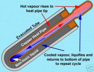
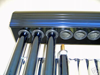
The collector consists of an array of
glass tubes. Inside the glass tubes are copper tubes filled with liquid.
These copper tubes are heated by the sun (they have black fins attached),
and the hot liquid rises to the top of the tube which is in contact with
a heat exchanger. Through this heat exchanger flows the water to be heated.
The key to this working so well is that the glass tubes are constructed
like a thermos flask. There is a vacuum between the inner and outer tube
which means that heat trapped inside cannot easily get out. Also being
round, it means the angle of the sun is not critical and the tubes receive
radiation over a much greater period of the day than would a flat panel.
As there is no water flowing through the actual collectors, they are immune
to frost damage. The whole array weighs only about 60 kg, with the weight
being only that of the glass tubes, heat exchanger manifold, and stand.
Retrofitting to an existing
tank.
A typical vertical water heater tank has
a cold water inlet right at the bottom and the hot water outlet right at
the top. A third connection at the top is for the TPR valve, but some heaters
combine this with the hot outlet. The heating element is located in the
lower quarter of the tank and thus heats the water above it. A tank made
for solar use has an extra connection about halfway up. This is where the
warm water from the solar panel is fed into the tank. The cold water for
the panel comes from the bottom of the tank. Thus when the panel is heated,
thermosiphon occurs. How to use an existing tank? The cold supply for the
panel is easy as there's already a connection at the bottom of the tank;
i.e. the cold water supply inlet. The hot output from the panel is the
tricky part. If it was merely fed into the top connection of the tank,
there could be conflict with the hot water return from the solar collector;
eg. if the water from the collector is cooler it will mix with the hot
water from the tank and thus reduce the outgoing water temperature. I eventually
discovered the trick is to use something called a "five way valve", or
"solar conversion valve".
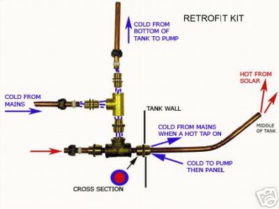
This diagram came from the eBay seller of my kit and
illustrates the five way valve.
What happens is that the cold water connection at the bottom of the tank performs two functions. The cold water is fed into here as well as to the solar panel. However, the hot water is also fed via this connection to a length of tubing inserted into the tank, the end of which is away from the cold inlet. So, cold water is drawn from the bottom of the tank, pumped through the solar collector, heated, and then injected into the bottom of the tank (away from the cold area) and rises to the top. Thus, no modifications to the tank are required. Obviously, the tube injecting the hot water must be of smaller diameter than the cold water inlet. Typically, the cold water inlet is 3/4" which allows a 1/2" injection tube. The remaining 1/4" gap is quite sufficient for cold water flow.
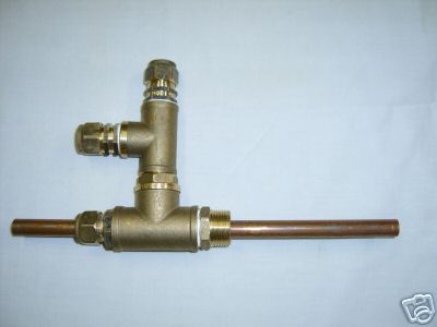
Five way valve made from ordinary plumbing fittings.
The length of copper tube protruding into the tank is somewhat longer in
my installation.
This type of conversion applies to a ground
standing tank with solar panels on the roof. Unfortunately, for thermosiphon
to occur, the tank needs to be above the collectors as hot water naturally
rises. With this type of installation a circulating pump is therefore required,
so unless this is powered from a photo voltaic panel the hot water is not
entirely free. However, the pump is only for circulation instead of having
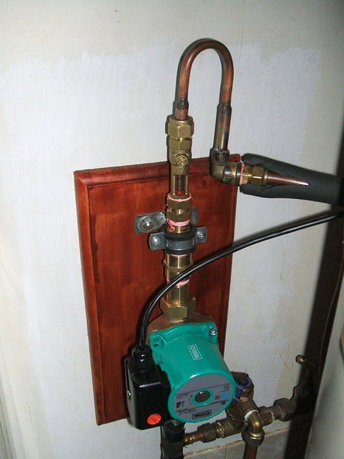
to push a head of water so power requirements aren't that huge. My Wilo
pump supposedly draws 46W. Somewhat cheaper to run than a 3.6KW element!
The controller means the pump only runs when the water in the solar collector
is warmer than that at the bottom of the tank, so it isn't running all
the time. In practice, the pump cycles every few minutes on a sunny day;
the stronger the sun, the longer the pump stays on. The Wilo pump was designed
for central heating systems so it's overkill for this application. It has
three speeds, which are actually selected by introducing different amounts
of capacitance in series with the motor. As it is, the pump does
not remain on continuously during hot sunny days, which indicates the speed
is not too slow.
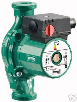
The Wilo circulating pump. It has three speeds, the
lowest of which is used for this application. It
is important to make sure the proper unions are supplied when purchasing
one of these. Do not use the cast iron body version (intended for circulating
anti freeze solution) as it will rust, causing impeded flow, as well causing
rust particles to interfere with the one way valve.
Use the bronze version instead.
What I did find very useful was to look
at installation instructions for commercially made water heaters, in particular,
the Rheem
Loline which is a solar retrofit. 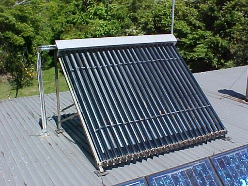
Evacuated tube collector installed on my roof. Note
the photovoltaic panels in the foreground.
The Installation.
First thing was to assemble the stand
and mount it on the roof. The stand is stainless steel and the roof is
zincalume. To those outside Australia, this is a zinc/aluminium material
with similar appearance to galvanised steel and is used for the same applications.
Given the corrosion possibilities with dissimilar metals in contact with
each other, I mounted the stand on neoprene pads before screwing it to
the roof. I simply obtained a sheet of neoprene from Clark Rubber and cut
it to suit.
It was rather convenient that the roof
area where the solar collector was to go, was right above the laundry where
the hot water tank is. Thus there would be a short vertical run of pipe.
There is approximately 10m of pipe in the circuit. To start with, I used
green lagged copper tubing for the pipe run. All the fittings were designed
to take 1/2" tubing. The short length of copper pipe protruding from the
heat exchanger manifold is a non standard size in Australia. Compression
joiners to connect this to 1/2" tubing were supplied.
Getting the pipe through the ceiling space
was the most tedious part as there was a piece of framework that had to
be cut away above the ceiling cornice. Once this was done, the pipes were
installed and the roof sealed with a Rooftite ( a neoprene gland attached
to the roof with stainless steel screws and sealed with silicone).
I was a bit concerned about mounting the
pump due to its weight and the fact that it was meant to be supported only
by the connecting pipes. The pump was not supplied with the correct unions
either. Instead were just simple 1/2" to 1" reducers with home made silicon
washers to seal the whole thing. I had to purchase the correct unions elsewhere.
I decided to mount the pump on a board with pipe clamps.
The plumbing was straightforward until
I attempted to make the five way valve. The way the Edwards tank is constructed
does not allow such a thing to work; not on the cold inlet anyway.
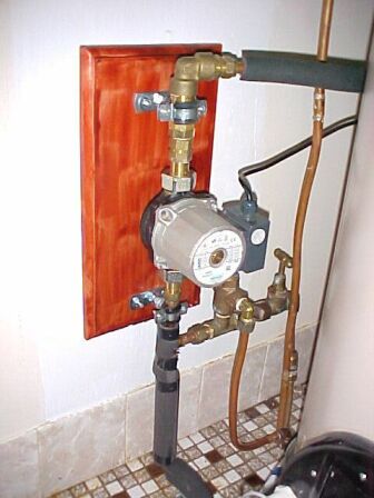
Pump installation and cold water plumbing. This was
the original cast iron pump.
Instead of the cold inlet simply being
a port in the side of the tank, it's actually a connection to an internal
pipe that runs underneath the tank to the centre. How did I find this out?
I tried making the five way valve and
inserting the hot water copper tube but found it didn't go very far.
The design of this tank has the hot water
outlet right in the centre of the top of the tank; not at the side. So,
I could actually shine a torch down and see inside the tank to learn of
its internal construction. Nice to see all that gleaming stainless steel
inside with not a hint of corrosion. How many glass lined tanks would be
like that after 11 years?
It was this top connection that solved
my problem, for this was the logical place to put the five way valve. There's
about 1.2m of copper tube going straight down into the centre of the tank
for the hot water to be injected. The hot water is thus fed into the tank
at the same location as if I'd put the five way valve at the cold inlet.
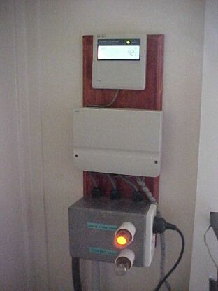
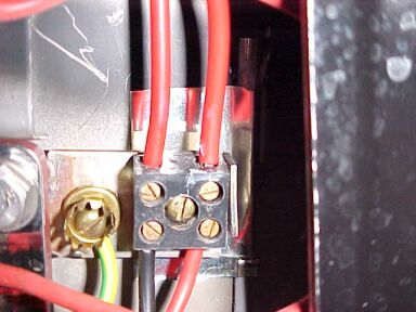
The diecast box at the bottom contains the relay for switching the electric element and socket for the pump. There is an additional switch that allows the element to be permanently turned off when required. Neon pilot lamps show pump and heating element operation.
Once I'd finished the plumbing, turned
on the water, and got the leaks out of the connections, it was time to
install the glass tubes. The instructions recommend talcum powder to lubricate
the neoprene glands in the heat exchanger, into which the tubes are inserted.
I didn't have this so I tried CRC2-26. This worked perfectly and the tubes
slid into position very easily. Next, the hose clamps at the base of the
stand were tightened to secure the tubes. Finally, the stainless steel
reflectors were attached between the tubes.
At this point I hadn't installed the control
unit so the pump wasn't running. By the time I'd finished inserting the
24 tubes I found the hot outlet on the heat exchanger too hot to touch.
Not my unit, but the Endless Solar version, this shows
how the tubes are inserted into the heat exchanger.
Within a few seconds of turning on the
pump I had to let go of the hot water pipe from the exchanger going into
the tank, as there was a burst of very hot water flowing through it.
It was at this point that I finally believed
these tubes might actually work.
One annoying thing during the installation
was leaking screwed fittings. I used compression fittings or soldered Yorkshire
fittings where possible. Even with copious amounts of teflon tape, the
screwed connections always leak. I've done them up to the point where the
threads are about to be stripped, and yet I can almost count on seeing
a drip when I turn the water on. So annoying did this get I just
ran solder into the threads. Problem fixed! I only did this where serviceability
isn't goint to be affected of course. The real problem is that many fittings
don't have a tapered thread and this is what's really required to prevent
the problem.
The final part of the installation was
to install the controller. To this are connected three thermistors. One
(designated T1) is inserted into the heat exchanger near the hot outlet
and the other is located at the bottom of the tank (designated T2). The
third thermistor (T3) is mounted at the hot outlet of the tank. Its purpose
is only to activate the electric element if the water has not come up to
the required temperature by solar alone.
T2 thermistor held against tank body by a piece of tinplate secured
under the terminal block.
The default setting of the controller is
such that the pump turns on when the collector temperature is eight degrees
warmer than the cold supply to the collector at the bottom of the tank.
The pump then runs until the temperature difference is four degrees.
Two other functions which are not really
necessary in my installation are frost and over temperature protection.
Should the T1 sensor detect imminent frost (default setting is two degrees),
the pump will circulate warm water until four degrees is reached. This
prevents the pipes freezing and bursting. This would be more applicable
to flat plate collectors, however. The other feature is to turn
the pump off should T2 reach 70 degrees. This stops the hot water flow
under extreme temperature conditions.
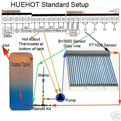
Diagram supplied for my solar heating setup. In addition
I have made use of the T3 temperature sensor input and the H1 heating control
for automatically switching the electric element. Unfortunately there's
an important omission: There should be a non return valve either on the
pump outlet or solar collector return to tank. Without this, reverse thermosyphon
occurs at night. The pump wiring via tank thermostat should be ignored.
The controller has a a feature where it
can switch on the element up to three times a day for a specified time
and until a preset temperature is reached. This temperature is sensed by
a third thermistor at the top of the tank (T3), where the water is at its
hottest. I simply pushed the thermistor in between the foam insulation
and the brass T fitting at the hot water outlet. While it isn't in direct
contact with the water, it works well enough as the brass is a good heat
conductor. In practice, I found the thermistor shows about three degrees
less than the water temperature. So, to have the element switch off at
50 degrees, I set the controller for 47 degrees. I have set the controller
so that the heating element is switched on (if it needs to be) at 17:30
for an hour, which is just long enough to get the water temperature up
to 50 degrees, from about 36 degrees, which is typical for a cloudy day.
This works in with my hot water requirements being mainly at night, which
is the best way to use a solar hot water heater.
The controller supposedly can switch 16A
for the heating element, but I find this hard to believe given it's all
on a printed circuit board and the relay doesn't look very substantial.
I decided to make a second box with a
contactor inside, as well as some neon pilot lamps to indicate when the
electric heating was activated, and when the pump was running.
The heating relay inside the controller
simply supplied the low current of the contactor coil which then switched
the 15A heating element. Unfortunately, the contactor having an AC coil
buzzes loudly at 50 cycles. As the whole thing is mounted on a hollow fibro
wall the sound is amplified to a large degree and is very unpleasant. I
fixed that by using a 12VDC relay with 250V 30A contacts. The relay coil
is fed from a small transformer and rectifier. Being DC it is totally silent
in operation. Because I don't always need the water heated automatically,
I put an extra switch in series with the transformer primary.
Electric heating.
It needs to be pointed out that a large
proportion of Australian electric water heaters normally run from an off
peak supply. That is, they are metered separately at a lower rate, but
the supply is only present overnight. This does not suit a solar heater.
Take the scenario where it's been a cloudy
day and the water hasn't heated up for evening use. Firstly, the off peak
supply does not become available until late, and then it takes an hour
or so for the water to actually warm up. Having then heated the water up
to full temperature by morning, imagine what happens if it's a sunny day.
Because the water is already hot, the
solar contribution will be mostly wasted. And the cycle continues. There
will be little saving.
Ideally, the water needs to be heated,
if necessary, prior to the evening/morning use, and only just enough. This
way, the electrically heated hot water is used in the evening and morning
only, and cooled down by mid morning when it's ready to absorb solar heat.
For these conditions, I've found switching
on the electric heating, if needed, is best done late afternoon, once solar
contribution stops. 5.30pm is my chosen time. From experience, I find that
only one hour of heating is needed to cover the night and morning usage.
So, the electric heat switches off at 6.30pm.
For this reason, the ideal pattern of
hot water usage is that most of it occurs in the evening, when the water
is hottest, leaving cooler water for the morning, ready for solar heating.
Furthermore, most people run their hot
water tanks at absurdly high temperatures. The default setting is often
70 degrees! 60 degrees is more than sufficient.
I am very sceptical of claims that certain solar powered devices will work in cloudy conditions, and evacuated tube collectors are no exception. The answer is simply that they will provide some heat, but the truth is not to a usable degree. The electric element is usually required after two days of cloudy weather. Having said that, the use of solar collectors on a cloudy day will still save electric power because the element is only heating the tank from say 35 to 50 degrees, rather than starting off at say 18 degrees. It takes less energy to obtain a 15 degree rise in temperature than 32 degrees would require.
What the kit supplier didn't tell
me.
Once into Autumn, something started to
become very evident. My suspicions of reverse thermosyphon at night was
confirmed as the pipes up to the collector remained warm even though the
pump was not operating. With cool night time temperatures outside,
most of the heat accumulated during the day was simply dissipating into
the night sky. I was beginning to think a non return valve was needed,
and as I looked at the installation manuals for the commercially made systems,
it was now quite obvious; they all used one. To put it simply, I was rather
annoyed that not only my kit supplier did not provide or mention the need
for such a valve, none of the other eBay sellers mention it. I eventually
decided on the RMC solar non return valve type SNR502. An ordinary non
return valve should not be used as it may not be intended for the high
temperatures in a solar hot water system. Luckily I'd seen the RMC price
list for this valve before buying one. It was around $57 retail. So, when
I rang up Reece to order one and was quoted $147, I looked elsewhere. Tradelink
in Penrith had one ordered for me in a couple of days, for the correct
price.
Having installed the non return valve,
the change in performance is like the difference between night and day.
The water is still hot in the morning! The pipes running up the collector
are cold at night as they should be, and now I can look at the T1 temperature
reading to see what the outside night time temperature is.
Quite obviously, eBay sellers of evacuated
tube retrofit kits do not understand the finer points of solar hot water.
They are merely importers from China. You are on your own if you buy one
of these kits; do not rely on what they tell you. Check that you have been
provided with adaptors for connecting Australian pipe sizes to the heat
exchanger manifold. If they're not supplied don't buy it unless you have
good lathe skills. You're unlikely to be able to get the non standard fittings
here. Having said that, I've learnt alot from this exercise, and hopefully
my notes here will enable your system to be successful too.
A further 'non mention' was that thermal
paste should be applied to the ends of the tubes where they insert into
the manifold. This not only seemed logical, but again the commercial instructions
specified it. I used ordinary heatsink cream as used with electronics.
Again, an improvement was evident after this was done.
Incidentally, you won't be eligible for government rebates with this kind of DIY conversion. For one thing, the eBay kits are not goverment approved, and the conversion would have to be done by a licensed plumber.
Cheaper power bill.
The first power bill since installing
the solar conversion was interesting. From $223 dropped to $161.
This is a quarterly account and I should point out that the billing period
in question commenced about a month before installation. So in actual fact
the saving might be more. In any case, that is a very pleasing result.
Even through winter, I've seldom used the electric element. Provided the
day is sunny, the water heats. Come to think of it, I've never used it
after a sunny day.
It is hard to believe that in Australia
with its climate that there are so few solar water heaters. They clearly
do work and save a substantial amount of electric power. I've had the electric
element switched on only about five times in about two months. Yet, people
continue to replace their failed (glass lined, of course) off peak or continuous
hot water systems with the same.
Performance.
While this installation has worked well
for me, I need to point out that it is supplying hot water needs for one
or two users. It is realised that the temperature is variable, and
not to expect huge volumes of burning hot water after an overcast day.
On the few days where the water is quite hot enough for a shower, but not
enough to wash dishes properly, a jug is boiled for that purpose (porcelain
type with exposed element, of course). The 1000W jug element run for a
few minutes is cheaper than turning on the 3.6kW electric boost for an
hour.
While the 125 litre tank works for one
or two users who are careful with hot water use, a larger tank is required
for more users if the electric boost usage is to be minimised.
The thing to remember is the tank capacity
is what ultimately limits the amount of hot water one can consume, not
so much the number of tubes. It is pointless to have 36 tubes to heat up
a little tank by mid morning with the rest of the day's heat having nowhere
to go. You will still only get that tank's capacity in hot water, and once
it has gone you have to wait until the next day for more. A larger
tank will however take in that heat and provide a reserve for a couple
of cloudy days.
I think 24 is the minimum number of tubes
that is practical for my part of the world, and that's with what I consider
the smallest practical tank. My rule of thumb would be to use 30 tubes
for a 180-250 litre tank and 36 for a 315 litre tank.
It is possible to simply daisy chain the
evacuated tube collectors if the heat output from one is inadequate (e.g.
use two 18 tube sets to get 36 tubes).
However, care would have to be taken to
see that excessive temperatures do not occur from using too many tubes.
It is simple matter to cover some of the tubes in summer if this occurs.
It is important to realise that high temperatures
are possible with a solar heated hot water supply and while one day the
water feels lukewarm, after a hot sunny day it can burn you. Remember,
the thermostat controlling the electric element has no control when the
water is heated by other means. So, don't just blindly turn on the hot
tap and put your hands under it expecting it to be the same temperature
it was the day before. If a licensed plumber does the installation for
you, a thermostatic mixing valve will be fitted to provide a 50 degree
limit, as this is required for all new hot water work.
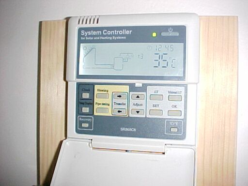
It is quite helpful to have the temperature
display where it will be seen. Not only does it give an idea of what to
expect when I turn on a hot tap, but also if I need to think about letting
the electric boost operate before the water gets too cold.
Later problems.
After a bit over two years operation,
the system was starting to work poorly. First suspicion was the non return
valve, and sure enough this proved to be faulty. I dismantled it and found
a lot of dirt inside keeping it open. Even after I cleaned it, it still
did not seal perfectly. So, again all the daytime heat was being radiated
into the night sky. At the same time, I noticed the pump was almost blocked
with its own sediment. Fairly obviously the cast iron body was a poor choice.
Another thing the supplier got wrong.
I contacted RMC about the valve and much
to my surprise sent me a new one for free. Apparently there was a known
fault with some of the valves around the time I bought the original.
It was great to get such service from
an Australian company. With the new valve in and the pump cleaned out,
all was good again.
However, reading operating instructions
for commercial systems got me intrigued to experiment with the pump switching
temperatures. The default for my controller is if the collector gets to
8 degrees more than the tank, the pump switches on. When the temperature
difference drops to 4 degrees, it switches off. It seemed to me that if
the pump "on" temperature was higher, then the water in the collector would
be hotter before it was pumped into the tank. After some experimentation,
I settled on 10 degrees. As for the "off" temperature, it seemed that it
should stop pumping once all the heated water had entered the tank. It
was quite obvious when this happened simply by feeling the copper tube
at this point.
I set the temperature difference so that
the pump switched off just when the water cooled again. This turned out
to be 7 degrees.
Broken Tube.
Around February 2012, I noticed a crack
at the bottom of one of the evacuated tubes. This would have been from
a falling branch. It took several months for the air to leak in; this being
evident from the tube changing to a whitish colour and becoming more transparent.
At that time of year, the loss of performance was not noticeable, but with
winter on the way I decided to obtain a replacement. By now it seemed that
58mm tubes were now the standard, as few suppliers had the 47mm tubes my
system used. Luckily I found someone with a few old tubes left over and
bought a couple of spares.
New Pump.
Another 3 years later, and again it was
back to reverse thermosyphoning at night. This time I decided to do several
things. As before, the pump was clogged by its own rust, so I decided to
finally get a bronze bodied one. And again, the one way valve had failed.
The supplier where I got the new pump from happened to sell a different
version of these, so decided to give it a try.
If it fails again, I will try a passive
method of preventing reverse thermosyphon. It's a method I've seen with
one commercial system. Briefly, the incoming hot water pipe from the collector
is formed into a U shaped loop, the bottom of which is below the connection
at the tank. The idea is that if this part of the pipe is left not insulated,
it will be cooler than the water at the connection. And heat does not flow
downwards. In theory this will prevent reverse flow. Another option I have
considered is a solenoid valve connected to the pump supply. However, such
a valve has to be able to work at the high temperature and low flow pressure
in the system.
The third modification was to install
a flow meter, as the rate at which water flows through the collector has
an effect on performance. Also, being able to see the flow rate allows
one to see if any blockages are forming.
New bronze bodied pump. One way valve is immediately above the outlet
connection, followed by the flow meter.
Small screw at top of flow meter controls flow rate.
The flow meter consists of a perforated
spring loaded disc. The water pushing against it opposes the spring force,
and thus the disc moves. Alongside is a calibrated scale to show litres
per minute. It appears the standard recommendation is a flow rate of about
100ml/min per tube. A screwdriver set ball valve sets the rate of flow.
Since installing the new pump, and now
being able to adjust the flow rate, I have gone back to the default of
8 degrees on and 4 degrees off, and have set the flow rate to 1.5 litres/minute.
This has made a huge improvement in performance.
It seems that my experiment of increasing
the temperature before the pump operated was flawed. This is likely to
be because there's a lot more time in between pump cycles which not only
gives time for the water in the pipe between the collector and the tank
to cool, but also while waiting for the pump to run, the solar energy isn't
actually going into the tank.
So, to take in maximum energy, it appears
best to have the pump run as much as possible while keeping the collector
temperature just above the tank temperature. This is effectively what happens
with a thermosyphon system. This means having the pump switch off temperature
not much above the tank temperature, and setting the flow rate slow enough
so the pump is almost running continuously on a sunny day at the peak of
summer.
Conclusions.
There is no doubt that solar hot water
works very well and I would now never use any other system. However, in
view of what I have learned with my system, there are some important points
to keep in mind: