Vertical Blocking Oscillator Transformer
Replacement
In my experiences with restoring valve
television sets, particularly ones from the 1950's, one of the most common
faults is the vertical blocking oscillator transformer failure.
Usually, the transformer shows signs of
impending failure before it actually stops oscillation. Such signs include
poor field linearity which cannot be adjusted out, strange looking interlace,
and poor synchronisation.
The worst transformers seem to be the
ones which are used in the plate circuit of the vertical oscillator (often
a 6BM8 triode). This type of oscillator design is common in the European
type of design, used by such brands as Philips and Kriesler. The other
type of oscillator circuit employing a blocking oscillator transformer
has the transformer in the cathode circuit of the oscillator triode. This
type is common in sets of US type design, such as AWA. It could be that
having the transformer in the cathode circuit means less turns on the windings
(lower impedance) thus resulting in better reliability. In fact, I don't
think I've ever had a failure of this type.
So, what to do? At first I would replace
the transformer with another one, but eventually it would fail again, and
I didn't always have the right transformer. Besides, the vertical locking
never seemed to be much good anyway. So, I decided to design an electronic
solution and eliminate the transformer altogether. Why this type
of circuit found favour I can't understand. Plenty of sets used a multivibrator
instead, eliminating the costly transformer.
While a few sets used a separate twin
triode for the vertical oscillator (often a 12AU7), most actually used
the output triode or pentode as the other half.
My design uses the separate oscillator
approach. I did this to allow flexibility of design; i.e. using it with
other sets than the ones I'm describing here. Also, using the output valve
in the oscillator circuit is more critical in that linearity and height
settings can change oscillator performance.
Philips 21CT335.
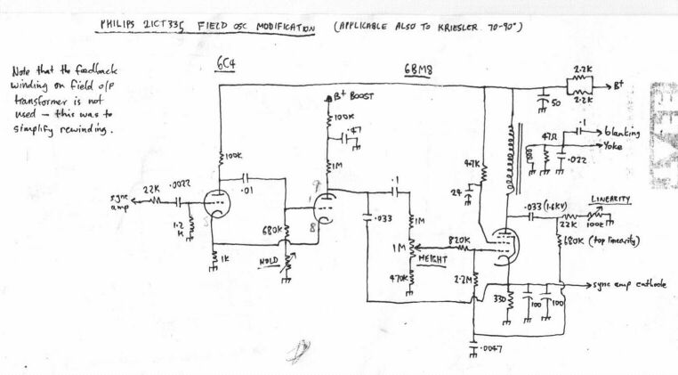
This first circuit
was implemented in my 1958 Philips 21CT335. This is a 21" 90 degree set
from 1958. A 6C4 triode was added to form the multivibrator in conjunction
with the existing 6BM8 triode. You can of course use other valves; a 12AU7
triode for example. I simply mounted the extra socket on a piece of aluminium
and screwed it to the wooden side panel of the chassis. The improvement
in performance was amazing. Lock was so strong that the hold control had
to be turned right to the extremes to cause loss of synchronisation.
Note that the output
side of the circuit is no longer original. That has nothing to do with
the oscillator modification and was actually done with the original oscillator
circuit in place. I had to rewind the output transformer as the primary
eventually went o/c. It's 3000 turns of 39 gauge wire if you're interested.
As it happened, after rewinding there wasn't enough room for the feedback
winding to go back on, so I ignored it and modified the circuit to a more
conventional design. Note also the blanking level has been increased. This
is due to the teletext problem.
HMV F1
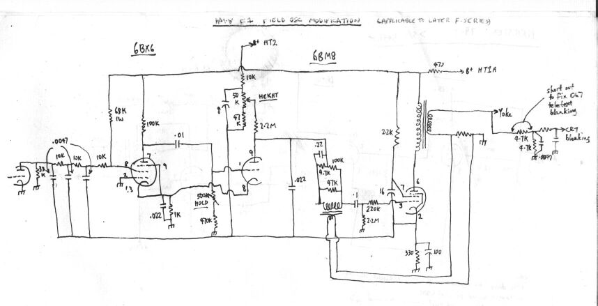
This next circuit
was designed for an 1957 HMV F1, but is obviously applicable to the other
F series chassis. These HMV F series sets are notorious for transformer
failure. Despite that, they are one of the best performing sets in Australia.
If you wanted a set designed to text book principles with no cost cutting,
this is it. As far as the vertical section goes, linearity is so good that
a user control is not provided. As you can see, current feedback is used
to optimise the waveform. The yoke current is sensed and fed back to the
6BM8 output pentode grid via a small transformer.
Again, the substitute
circuit uses a cathode coupled multivibrator. The transformer was removed
and the 6BX6 mounted on an aluminium bracket in its place above the chassis.
In view of how the sync pulses are fed in to the oscillator, I decided
to use a pentode with the sync pulses fed into the screen grid. This worked
exceptionally well. Incidentally, an interesting feature of the HMV is
that the vertical oscillator plate supply is taken from the normal B+ rather
than the B+Boost. No doubt the feedback network in the output stage compensates
for the less than linear waveform.
HMV F5.
The last of HMV's
21" 90 degree chassis.
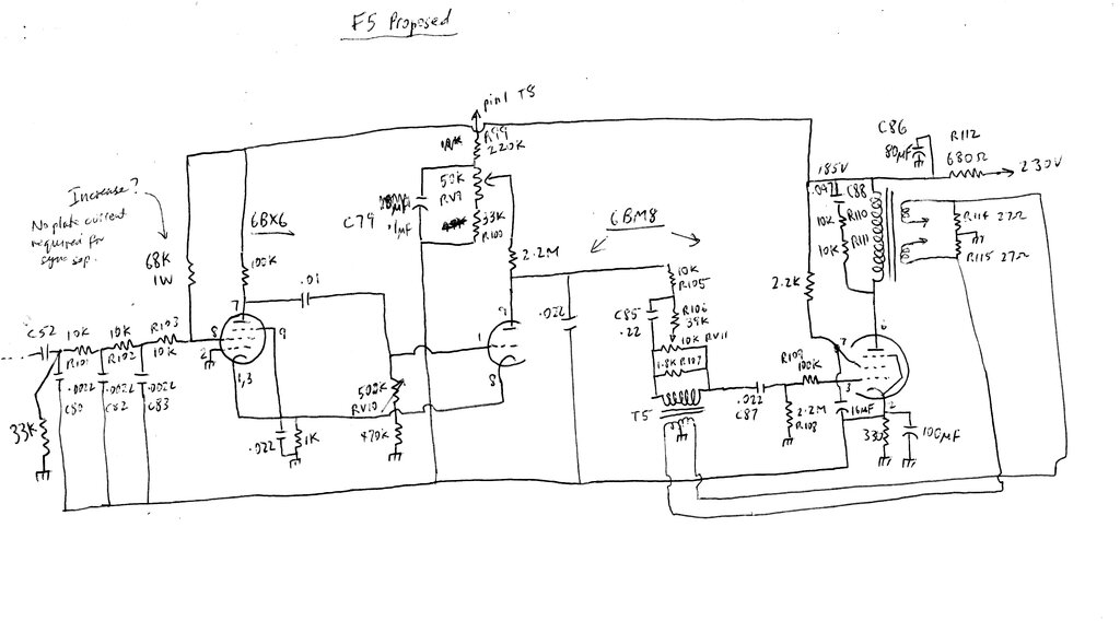
This circuit is based on that of the F1.
Its main differences is that there's a user adjustable linearity control,
and also the sync separator connection is different. In the F1, the plate
load of the sync separator is actually the input filter circuit of the
vertical oscillator. In the F5 the plate load is separate, and the sync
pulses are capacitively coupled by C52. This version of the circuit has
been tested by a fellow TV enthusiast here https://www.youtube.com/watch?v=rsqrgkWEByE&t=1s
Kriesler 79-1.
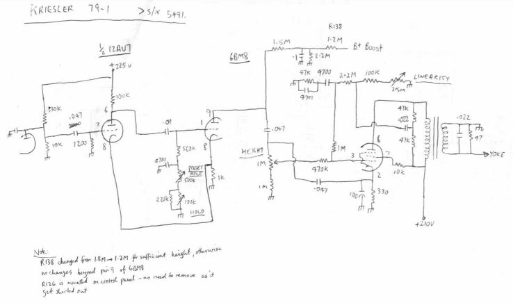
The third circuit
was for a Kriesler 79-1. Not suprisingly, the design is similar to
the Philips.
Initially, out of
curiosity I did try using the 6BM8 pentode as one half of the oscillator.
While it worked, it was unreliable and critical, so went back to the tried
and trusted method. I have a number of 12AU7's with one triode faulty,
so I used one of those. Note that R138 is reduced to 1.2M in order to get
sufficient height. To see how good
the linearity is, have a look here.
It should be obvious
that the circuit can be adapted to other sets, but clearly some experimenting
will be required to optimise performance.
Home