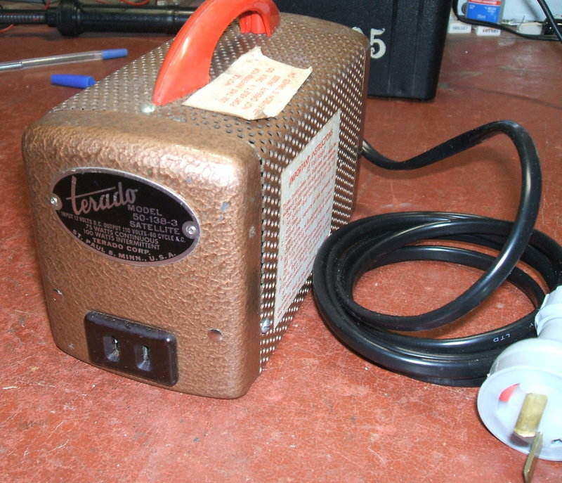
This inverter is identical externally to the 50-127 described here.
The ratings are the same as the 50-127, with an output of 110V 60c/s at 75W continuous and 100W intermittent. It is not clear why there are two Terado models that look the same, with identical ratings. However, an internal look shows things to be quite different.
The most obvious difference is the use
of a dual interrupter vibrator; something I was expecting to find in the
50-127 but was noticeably absent. Instead what appears to be a standard
single contact type was used in that model. It could be they upgraded to
a dual interrupter type for longer vibrator life, and hence produced the
model described here.
In the 50-138-3, the vibrator is a 1006
dual interrupter type with a 6V driving coil. For 12V use, a 22R series
resistor is used.
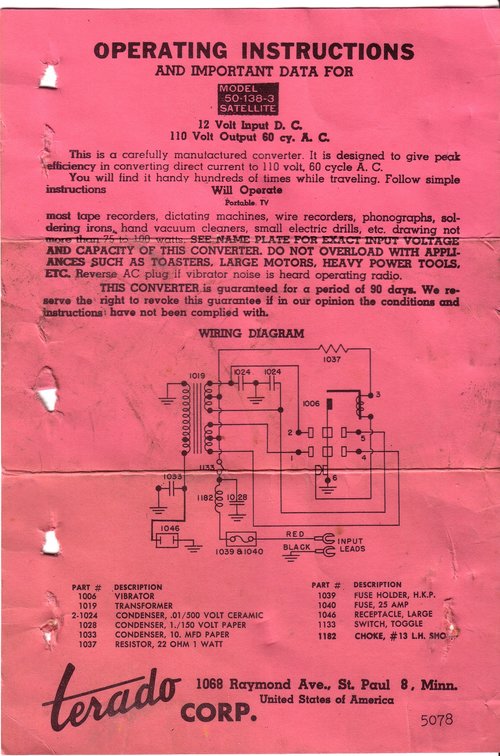
The transformer primary has two separate
windings which is the correct method when using a dual interrupter vibrator.
Doing so provides more equal current sharing between the two contact sets.
Buffer capacitance is 10uF on the secondary only. There is no other RF
output filtering. Input filtering is provided by a choke and condenser
in the same way as the other models. RFI suppression is also provided by
.01uF ceramic condensers across one set of contacts. Why the other set
is not bypassed is not clear.
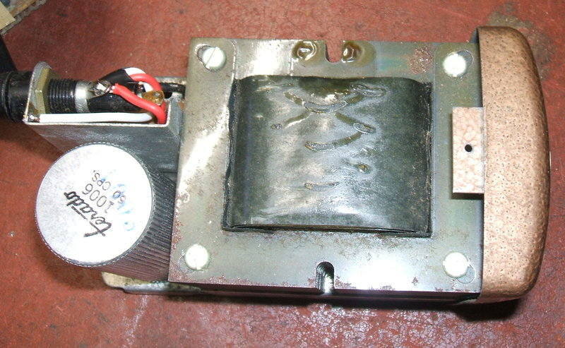
Construction is the usual compact layout as per the other Terado inverters. All that is above the chassis is the transformer, vibrator, and fuse.
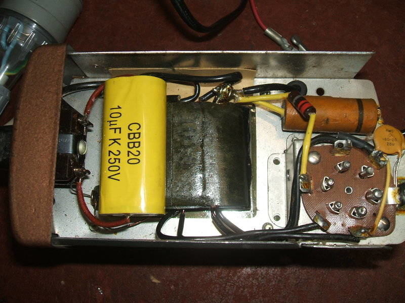
Under the chassis shows the new 10uF buffer condenser and other components. The 1uF paper bypass can stay as leakage is harmless.
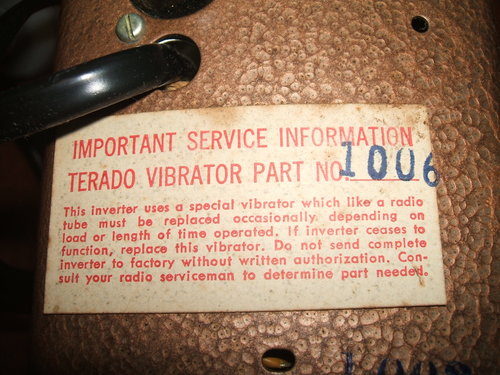
It seems that Terado wasn't interested in servicing their own products.
Indeed, it is undesirable to run the inverter
with no load, hence this warning. Experiments showed that 2uF of buffer
capacitance was preferable for very light loads, but on full load the specified
10uF is actually required. Evidently, Terado gave up on the high voltage
overwind and smaller buffer capacitor as used in the 50-127.
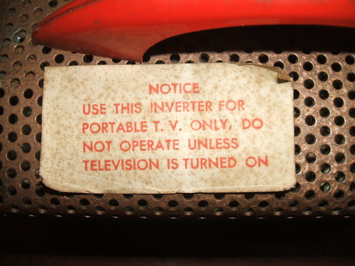
The specification for using a "Portable
TV Only" is interesting. Why not any other load? A portable TV for 110V
will have a series heater string using 450mA or 600mA valves, so that in
itself is a purely resistive load. The B+ will come from either a half
wave rectifier, or a half wave voltage doubling rectifier. The current
draw will therefore be asymmetrical, causing more loading than a full wave
rectifier load would. It appears that this inverter is therefore beefed
up to take care of this, so such a TV set would be better used with the
50-183-3 and not the 50-127. This would imply that purely resistive loads
of more than 75W could be used on this inverter.
However, it does seem the ratings are
being pushed as they are. If the TV set uses 450mA valves, the power to
heat them is 50W, leaving only 25W for the B+, which equates to 220mA,
about what a small set would require. For a set with 600mA valves, things
are not looking good. Here, 66W is drawn by the heaters, leaving only 9W
for the B+. That's only 81mA - hardly enough to run a TV set, even a small
electrostatic one.
Obviously, the "Portable TV" must be one
using 450mA valves. There is no way a non technical person would know if
this was the case. One possible explanation is that this inverter was actually
supplied with a specific TV set as a package. In fact, there is some mention
of certain GE portables being sold this way in the 1960's. As the Compactron
valves used in these sets have 450mA heaters, it would allow just enough
current for the B+.
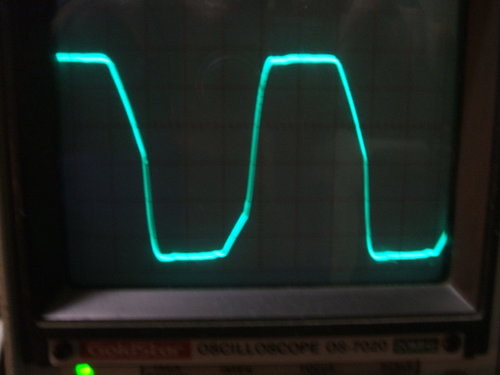
The output waveform is as it should be.
Because there's a possibility of one set of vibrator contacts not working
and the user not being aware of this, all four were checked with a light
bulb in series with 240V to ensure they were clean and working. A new 12V
supply cable with two pin polarised plug was fitted, and the paper buffer
capacitor replaced with a new polypropylene type.