This compact little inverter came to me
from a very kind reader who must have done an internet search on it, and
found my articles on Radar inverters which have
been described here.
Radar started making solid state inverters
in the late 1960's. Surprisingly, I have found very little advertising
for them. Yet, with this 40W model, I now have four in my collection. It
would appear that Radar stopped inverter manufacturing in the late 1980's,
but by this time the company was known as Invertech, this name having existed
since at least as far back as 1981. There is no mention of Invertech on
this inverter, but as will be explained later this is probably not surprising.
One of Radar's first inverters was a 40W model with a variable frequency control. The inverter described here would be one of their last, and is fixed frequency.
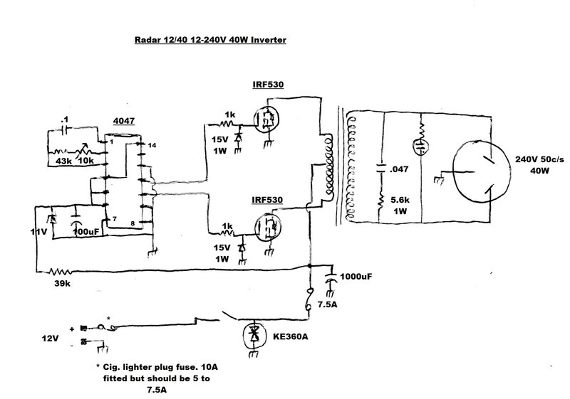
Hard to imagine a simpler circuit for a driven inverter.
The first noticeable aspect of design is the use of Mosfets. All my other Radar inverters use bipolar transistors for the switching function. It would appear from the date stamp on the Mosfets, that the inverter was made in 1987 or later. Evidently, Radar was keeping up with technology by using them when they became available. The advantages of Mosfets over bipolar transistors is firstly the very low "on" resistance. This means minimal voltage drop between the source and drain terminals, and thus little power dissipation. In fact, the heatsinking requirements are minimal. Secondly, since the gate presents a virtual open circuit and are thus voltage driven, drive requirements are minimal, and they can be driven directly from CMOS circuitry. Transistors, on the other hand, are current driven and require a buffer stage if driven by CMOS.
One thing I like about the Radar designs is they use conventional circuitry. They are conservatively designed, using standard components, and 'nothing weird'. This, and the use of an iron cored transformer operating at 50c/s, means they are rugged and reliable. Over the years I have gotten away with plugging things into my Radar inverters that would have instantly killed the modern switchmode type.
In the case of the 12/40, it's hard to imagine a more simple circuit. And the reality is, there's no need for it to be any more complex. A 4047 CMOS multi-vibrator provides a 50c/s square wave with anti-phase outputs. The 4047 is a popular choice for inverter circuits because it provides an equal duty cycle. Oscillation frequency is determined by the 0.1uF and 10k + 43k time constant. The 10k trimpot of course is used to adjust the output to 50c/s. Being free running, it would not suit a clock for long term accuracy, but for turntables and the like, it is quite adequate. The 4047 is fed from the 12V supply via a decoupling circuit consisting of a 39k resistor and 100uF capacitor. An 11V zener diode (BZX79C11) protects the IC from spikes on the supply. 39k is a very high value of decoupling resistor, but it must be remembered that the 4047 is CMOS and draws very little supply current. Because of the 39k resistor, the 100uF filter capacitor takes a couple of seconds to charge, giving a soft start effect when the inverter is first switched on.
The square wave is available at pins 10 and 11; the outputs being 180 degrees out of phase with each other. The Mosfets are IRF530's and their gates are driven from the 4047 via 1k gate resistors. Connected between the gate and source are 15V zener diodes (1N4744AP) for gate protection. The gates are prevented from going negative, or more than 15V positive.
The IRF530's of course switch the primary of the power transformer in the usual way. Internal drain-source diodes of the IRF530's protect them against back EMF. These diodes will also provide protection in case the inverter is connect to the 12V source with wrong polarity. The diodes will then conduct causing the 7.5A fuse to blow.
On the secondary side, there is a damping circuit consisting of a 0.047uF 630V capacitor and 5.6k resistor. A neon indicator shows when the 240V output is present. Unlike my other Radar inverters, this one has the earth pin of the output socket connected to the case. Additionally, the negative side of the supply is also connected to the case.
Input comes from a fused cigarette lighter plug. Across the supply is a EIC54 KE360A Transient Voltage Suppressor diode, which protects the Mosfets from excess voltage, which might come from spikes on a car electrical system. I haven't been able to find specific data for this diode, but it appears the clamping voltage is around 33V from data on some diodes with KE360A in their number. (Neither have I tried to measure it).
Note the small heatsinks, made possible by the use of Mosfets.
Construction.
This was intriguing to say the least.
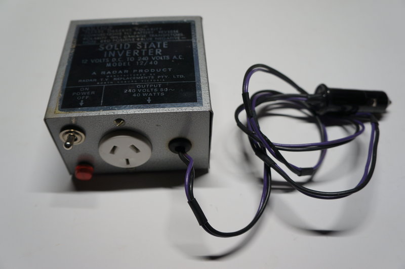
From the outside it looks like any other mass produced commercially made
product, except for one thing. The power lead is two separate wires, secured
together at intervals with heatshrink tubing, before terminating in the
cigarette lighter plug. Normally, a figure eight cable would have been
used. The fact that the positive wire is purple and not red is against
convention. The black (negative) wire, instead of running straight to the
PCB, is instead joined under a piece of heatshrink tubing to a smaller
gauge wire, which then goes to the PCB.
The case in which the inverter is assembled
appears to be designed for a step down transformer; possibly for a 32V
trouble light. I say this because there's a hole punched in the back for
a cord grip grommet. This has been blanked off with an ill-fitting plastic
plug.
Furthermore, there are numerous unused
holes in the base of the cabinet. Incidentally, the inverter transformer
is secured with only three screws; the fourth screw location is in the
way of one of the dimpled cabinet feet and cannot be secured.
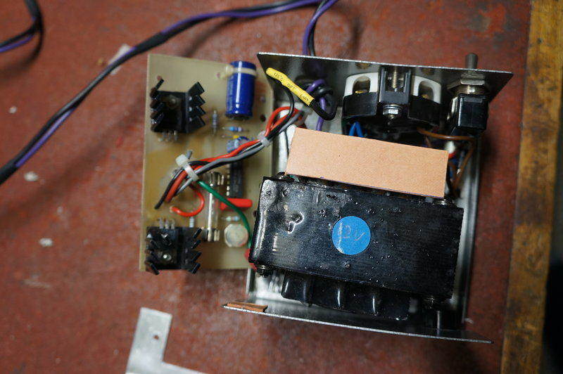
Construction is very compact. The PCB appears to be from another model of inverter, since there have been extra mounting holes drilled (not used), and the mounting holes used here have been drilled through the model number etched on the PCB. There is one unused component hole on the PCB, and the 15V zener diodes have been mounted as an afterthought, on the track side. The bracket used to mount the PCB is obviously not mass produced. It has been partially cut by a hacksaw and bent up in a vice.
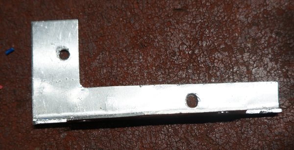
PCB mounting bracket looks very home-made. The vice jaw marks can
just be seen.
At this point I was wondering if this inverter had simply been assembled by an employee out of surplus parts as a one off item. The bracket and non professional power cable seem to support that. In comparison, the 100W and 300W inverters are constructed with nothing home-made about their appearance. Most perplexing of all was, how had this inverter been assembled?
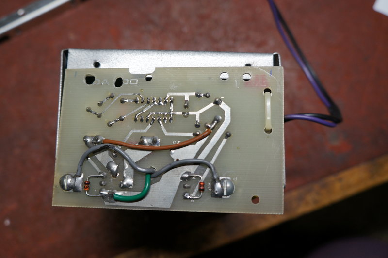
Note zener diodes on track side and model number drilled through.
A close look reveals felt pen marks used to line the PCB up with the bracket.
To extract the PCB requires an amazing
amount of dexterity. Replacing the 7.5A fuse would be a major exercise.
The screws securing the bracket to the PCB are completely inaccessible
since they are covered by the side flange of the case. So, the bracket
has to be removed from the bottom of the case first. However, the nuts
are down in the depths under all the wiring and extremely difficult to
get at. The only way I could do it is to use a pearl catch. This was after
removing the transformer screws first - and these are almost just as difficult.
I just cannot see how something made in a large quantity would be designed
this way. For some of the screws, the shakeproof washers had been placed
under the screw heads rather than the nuts. This is not the correct way
to do things, since it's the nuts that become loose, not the screws. Besides,
the shakeproof washer makes it difficult to tighten the screw, when it's
placed there instead of under the nut.
The negative end of the TVS diode is earthed
through a solder lug under one of the transformer screws. Covered in paint,
one has to wonder how reliable this connection is. It should have been
made with a direct connection to the negative. Similarly, the negative
connection is made to the case at another of the transformer mounting screws.
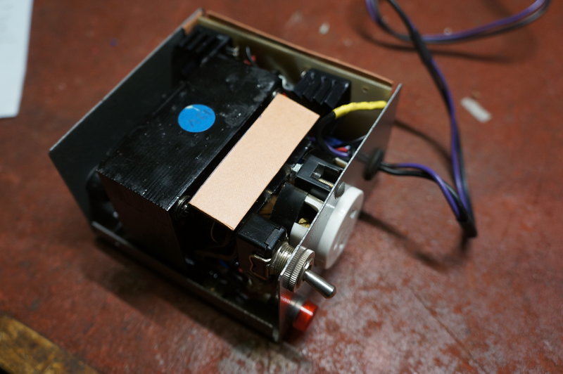
Note the extremely compact construction.
Subsequent correspondence with the previous owner filled in a few things about the mysteries of this inverter. Apparently, he had added the 15V zener diodes and TVS. Also, it appears that the ebay seller, who the inverter came from, was a relative of a Radar employee who designed it. It appears to have been made as a prototype, which explains some aspects of construction, and it had supposedly also never been used, which would make it a significant part of Radar history.
Output voltage for the Radar 12/40 was
measured over a range of lamp loads. The input voltage was maintained at
12.6V at the cigarette lighter plug.
| Load | Input Current | Output Voltage |
| No load | 260mA | 265V |
| 11W LED | 1.3A | 252V |
| 15W incandescent | 1.45A | 246V |
| 25W incandescent | 2.3A | 233V |
| 40W incandescent | 3.4A | 216V |
| 40W incandescent | 3.6A | 240V** |
Efficiency is very good. Under full load with the output at 240V 40W, input power is 49.7W. Efficiency is then 80%. With a 15W load, it is slightly better at 82%.
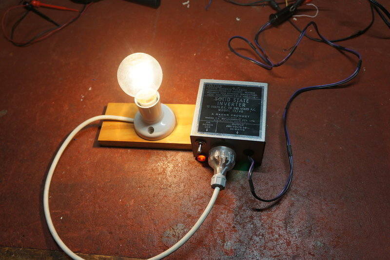
Inverter powering a 40W incandescent lamp.
Regulation was typical for this kind of inverter. With the input at 12.6V, output was 216V fully loaded with 40W. It was necessary to increase the input to 13.8V to obtain 240V. It is not known if the "12V" input is meant to be that of a car electrical system with the engine running, in which case 13.8V would actually be the input voltage. In any case, the kind of loads this inverter would be used with are not normally voltage critical.
Waveforms were observed with a 40W incandescent lamp, and a 15W fluorescent lamp with low power factor (i.e. no phase correction capacitor).
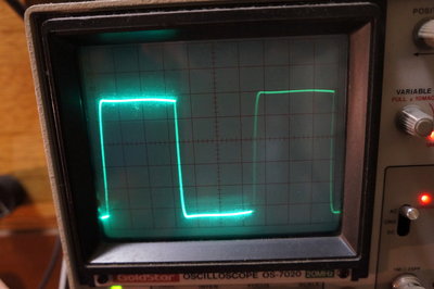
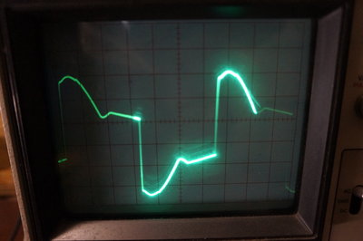
At left is the output with a resistive load; at right is with a
fluorescent lamp.
The inverter didn't seem to mind the fluorescent lamp load, although efficiency wasn't great, with about 3A current drain. I didn't try phase correcting it, but chances are efficiency would improve. The inverter output was high at around 256V, which would be due to the inductive effect of the load.
To sum up, it's a very cute and compact inverter, with excellent performance. The partial home-made aspect of it is interesting, but this does not detract from the excellent electrical design. Definitely one of my favorites, and one I was pleased to add to my collection.