Made from oddment parts, this provides a regulated 240V supply.
Made from oddment parts, this provides a regulated 240V supply.
Back in 1992, this device was built to
compensate for an unsatisfactory mains supply in a previous place of residence.
The house was the last on the line, some distance out in the bush, and
suffered from low mains voltage. The house was supplied with three phases,
and during the day, the best phase would provide 230V, and at worst, the
supply would drop to 180V at night in winter. It was so bad that radiator
elements would glow a dim red instead of the normal bright orange. The
motor in the clothes dryer would not get up to enough speed to activate
the centrifugal starting switch. Most annoying of all was valve television
sets, with a shrunken picture lacking in contrast. In particular, the set
I was using was a Philips 21CT335. I had a Variac next to the chair from
which I viewed the set, and would adjust it as the mains fluctuated. The
picture height was set so that it would begin to underscan with less than
240V, and by this I could adjust the Variac without having to actually
measure the voltage.
While this scheme worked, it required
manual adjustment. The danger was if the mains voltage increased with the
Variac already set to increase the voltage, then the TV would be supplied
with excess voltage, which is obviously undesirable.
Thoughts turned to constructing an automatic
regulator, and the circuit to be described is the result.
Increasing the Voltage.
It's easy enough to configure an ordinary
step-down transformer to provide a permanent increase or decrease in mains
voltage. The primary is connected in the normal way across the mains, and
the secondary connected in series between the mains supply and the load.
If the two windings are connected in phase, the voltage will add. For example,
if the secondary winding is 22V, and the mains voltage is 240V, the load
will see 262V. Conversely, if the windings are connected out of phase,
the load voltage will be reduced by 22V. The load will see 218V.
We can see it's a convenient way of operating
European 220V appliances from Australian 240V mains. Indeed, I did just
that with a previous refrigerator having a 220V compressor which overheated
on 240V.
The transformer ratings don't have to
be as high as may be first thought. For example, if we want to operate
a 500W 220V load, the transformer secondary would be 20V and rated for
2.2A. This is because 500W at 220V is 2.2A, and this is the only current
flowing through the secondary winding. As a result, the transformer is
rated at 44VA and not 500VA. The same principles apply when
using the transformer to increase the voltage.
Saturable Reactor.
Having increased the mains voltage to
compensate for a low supply voltage, we need to ensure that the output
voltage drops as the input voltage rises. Several schemes come to mind.
One could use a linear regulator with a high powered transistor. Because
of the AC supply, a bridge rectifier would also be required so the transistor
only saw DC. However, allowing for, say, a 200W load, the dissipation could
become excessive with a high mains supply.
Another option is to use a thyristor to
chop the mains waveform, so that the output is 240V. Unfortunately, while
this would be satisfactory for a load such as an incandescent lamp, it
would not suit an electronic load such as a TV set. This is because the
waveform is distorted by this method of control. The peak and RMS voltages
are no longer related. Additionally, the power supply in the TV set would
probably not appreciate the waveform.
To overcome these limitations, I used
a saturable reactor circuit. Since I didn't have a 'real' saturable reactor,
I made an equivalent using ordinary power transformers. Briefly, a saturable
reactor functions as a choke in series with the load. Since the reactance
of the choke is dependent on the inductance and frequency, it is obvious
that if we can control the inductance, then we can control the reactance,
and thus the voltage dropped.
So how do we electronically adjust the
inductance of a choke? Simply by causing the core to saturate to a lesser
or greater degree, by passing DC through another winding. The advantage
is that the control current is not very high, and there is no power dissipation
from the voltage being dropped.
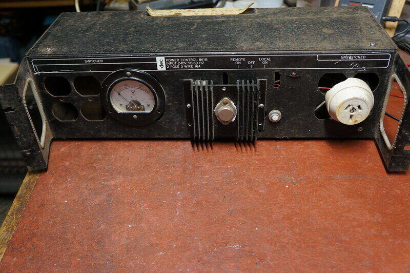
Construction of the Regulator.
The regulator was built out of oddment
parts which I had. It was built for functionality more than looks, as can
be seen from the photos. The enclosure was a power control box from a PDP-11
computer, and the two power transformers used as the saturable reactor
were also from PDP-11 equipment.
The Circuit.
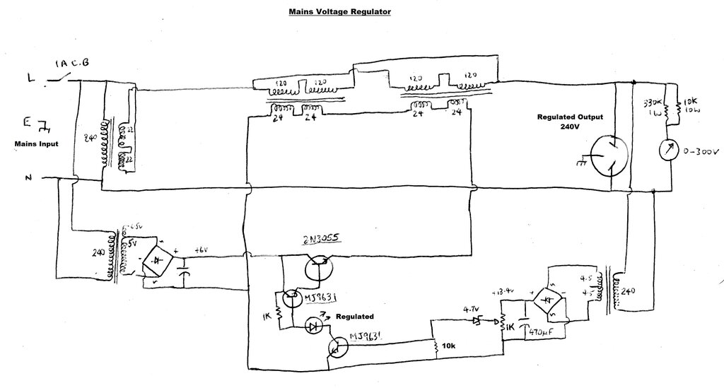
The incoming mains is boosted by a 44V
transformer. It's an unknown type with two 22V secondaries, rated at about
2A. Therefore, with a 240V input, the boosted supply is 284V and it could
handle a 500W load. A 1A thermal circuit breaker provides overload protection.
Next in line is the saturable reactor.
This consists of two large power transformers which would each be rated
at about 200VA. Each transformer has two 120V primary windings, and two
24V secondary windings. These are connected so the transformers are 240V
to 48V.
Both transformer primary windings are
connected in parallel, and become the impedance in series with the boosted
supply.
Now, to get the transformers to work as
a saturable reactor. The reason for using two transformers instead of one
will also become apparent.
We can't simply use one transformer in
series with the output and put DC through its secondary winding. Connected
thus, there would be AC produced by the secondary, since the primary is
being fed with something close to its normal input voltage, when current
is flowing through the load.
But, if we have two transformers, we can
connect the secondaries out of phase so the AC voltage cancels out. It
then becomes a simple matter to feed DC through the secondaries without
any AC being produced. Why not use just one transformer, but with two secondary
windings connected out of phase? Yes, there would be no resulting AC, but
since the windings are on a common core, it won't be possible to cause
saturation. This is because the windings are on a common core, and the
direction of winding cancels out any DC magnetic field.
The DC control current comes from a simple 6V power supply. The transformer used was from a low voltage reading light, and has a 5V and 6.5V tapping, with a current rating of about 4A. There was a thermal circuit breaker included with the transformer and this was retained. The 5V is rectified, and filtered with a capacitor; the value of which I have long forgotten. It's obscured by the mounting clamp, but it looks to be about 10,000uF. It's not critical. The current is fed into the saturable reactor via a 2N3055 transistor, used in conjunction with a MJ9631, to form a Darlington pair. The base current of this MJ9631 determines the saturation current, and thus the inductance of saturable reactor.
Base current for the MJ9631 comes from
a 1k resistor. This provides enough to cause the 2N3055 to saturate, if
need be.
To control the base current, another MJ9631
is used. As the base current of the 2nd MJ9631 increases, it brings the
base of the first MJ9631 to the negative of the 6V supply, reducing its
base current.
The feedback circuit uses another transformer to provide the error voltage. This transformer is a 9VCT 150mA type. Its primary is connected across the output socket, and the rectified and filtered voltage from its secondary is therefore dependent on the output voltage. Typically this is around 13V. This is fed via a 1k potentiometer, the wiper of which passes through a 4.7V zener diode into the base of the 2nd MJ9631. The adjustment of the 1k pot determines the output voltage. There is a LED in the collector circuit of the 2nd MJ9631. It shows when this transistor is conducting, indicating when the output is regulated. If the input voltage falls to the point the circuit cannot regulate, the 4.7V zener will not conduct, the LED will not glow, and the 2N3055 will saturate. At this point there will be minimal drop across the saturable reactor.
In summary, the operation of the regulator operates is as follows:
As the output voltage rises, so does the
DC voltage across the 1k pot. Part of this voltage passes through the 4.7V
zener diode. When the voltage at the pot wiper rises above 4.7V plus the
base-emitter junction voltage (600mV) of the MJ9631, the transistor starts
to conduct.
This pulls down the base current of the
2N3055-MJ9631 Darlington pair. The 2N3055 emitter current is reduced, reducing
the DC current through the 48V secondaries of the transformers used as
saturable reactors. This causes the inductance of the 240V primaries to
increase, thus reducing their current, and therefore the voltage to the
load.
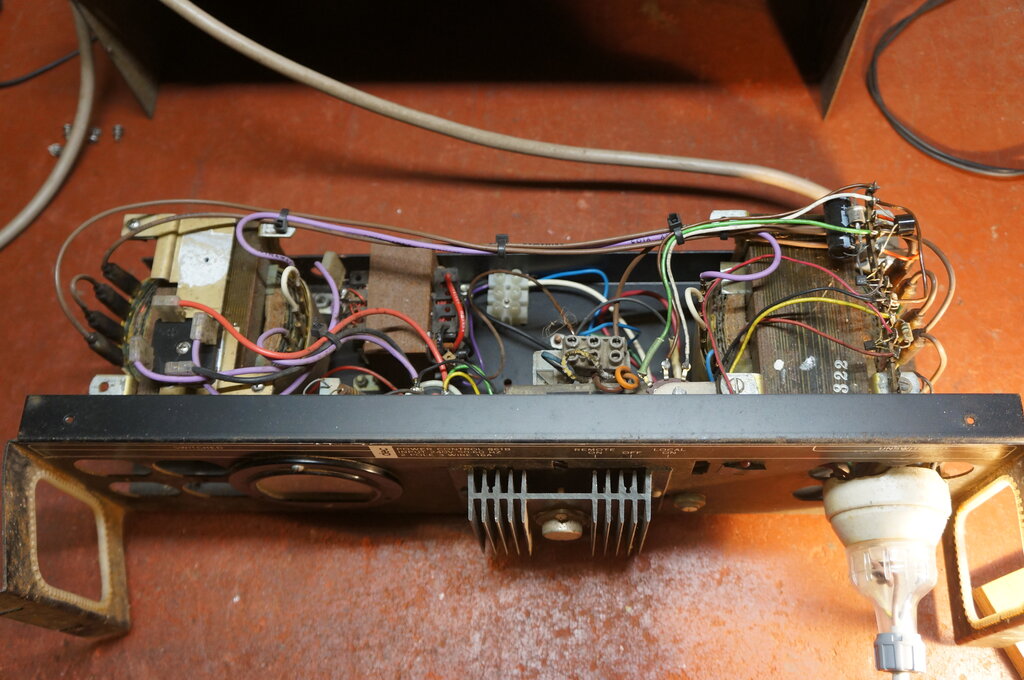
The two 200VA transformers can be seen at either end of the chassis.
To complete the regulator, an output voltage
meter was included. This is a true RMS type using a thermocouple.
The regulation characteristics are shown
below, with the regulator loaded by a 100W incandescent lamp.
| Input Volts | Boosted Volts | Output Volts (100W load) |
| 180 | 214 | 208 |
| 190 | 230 | 220 |
| 200 | 241 | 232 |
| 210 | 240 | 240 |
| 220 | 265 | 250 |
| 230 | 277 | 239 |
| 240 | 284 | 240 |
| 250 | 300 | 243 |
| 260 | 313 | 250 |
Regulation characteristics with 100W resistive load.
In theory, regulation could be improved below 200V by increasing the secondary voltage of the boost transformer.
The regulator certainly served its purpose,
and the TV set was able to work properly with the low mains voltage. Since
moving to another location, the mains supply is very well regulated, and
the regulator is no longer required. It is being presented here for those
who might find themselves with a problematic mains supply.
Anyone constructing it will need to have
an understanding of how it works, and be prepared to experiment, in order
to use available components, and to determine their ratings. The 6V supply
current peaks at 2A with an input voltage of 206V. The 9V transformer provides
hardly any current, so the lowest power type available can be used here.
One point of note is the 470uF filter is higher than needed, and causes
a lag in regulation. It could be reduced considerably to the point where
ripple only begins to appear across the 1k pot.
The two transformers used for the saturable
reactor need to be identical. Other secondary voltages should work; the
point being that enough saturation current can flow. Before the unit is
tested, it's important to see that the transformers are phased correctly,
so that no AC is present across the series connection of the two secondaries.
This must be done before the secondaries are connected to the DC control
circuit.
Their primary current rating will ultimately
determine what the output load rating is. For example, if the load is 120W
(500mA), that means both primaries need to be rated for 250mA, which would
imply each transformer would need to be rated for 60VA. In other words,
the transformer VA rating needs to be at least half the load power. Since
200VA transformers were used in the prototype, the maximum power rating
would be 400W. The 1A circuit breaker limits this to 240W continuous.
Limitations.
The saturable reactor is simply an impedance
between the boosted supply voltage and the load. As there is a certain
amount of inductance, even when no DC flows through the transformer secondaries,
it's obvious that the output voltage cannot be reduced to zero with no
load. This is the same situation that would occur if a variable resistor
was used to control the output voltage.
Therefore, the output voltage with no
load is the same as the boosted voltage. If the mains input is, for example,
260V, the no load output is 313V. It is important to realise this voltage
will be present at the input of the appliance so connected, if it happens
to be drawing no current. Any MOV's or filter capacitors will be exposed
to this higher voltage if they are on the mains side of the power switch,
and the switch is off. As stated previously, this regulator was designed
for a valve television set where the current draw is always high enough
to prevent any such problems. It should be noted also that if the mains
switch of the appliance is off, while connected to the powered up regulator,
the switch contact voltage rating may be exceeded. The switch on the appliance
should always be left on therefore, and the power switched on the input
side of the regulator.
With the regulator as constructed, the
mimimum load required for proper operation is about 100W. Below this, the
output voltage can be excessive when the mains input exceeds 210V.
With the output loaded at 200W, regulation
was such that a mimimum of 220V output was obtained with an input between
195 and 226V. Because of the simple control circuit, the output voltage
dropped off with this higher load, even when the mains input went above
226V.
This was improved on when the 1k pot was
re-adjusted. The 1k pot should be adjusted to suit the particular load,
and the output checked with the intended range of input voltages. A more
efficient error amplifier would improve on this.
One final note is to do with power factor.
Since the load is being connected to the mains via an inductance, a lagging
power factor results. With the prototype, the power factor (using a 100W
incandescent lamp) varied from almost 1 at low input voltage, to 0.8 at
260V when the series inductance was greatest. This is not problematic with
the public mains supply, but if one has ideas of using this regulator with
an inverter or portable generator, it needs to be kept in mind, since these
power sources might not be so tolerant.
Testing was done with a double 20W fluorescent
lamp with a power factor of 0.5. (370mA current draw with an apparent power
of 89W). This did not cause any problem with the control circuit. Output
was maintained at 220-250V with an input of 197 to 260V.