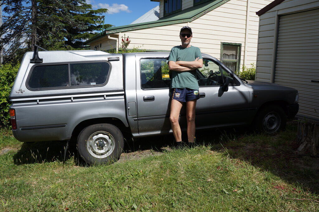
Yours truly with the 1996 RN85 Hilux. They got the design right for the most part.
Yours truly with the 1996 RN85 Hilux. They got the design right
for the most part.
When I purchased my 1996 Hilux, a multitude
of small jobs were required, which at 353,000km and 26 years old, was not
surprising. However, neither distance travelled or age is a bad thing when
dealing with an old Hilux.
One of the faults was the heater fan not
operating on all speeds. It is the usual setup of a tapped resistor in
series with the fan motor, and a switch to select the appropriate tapping.
The only choice was the lowest two speeds, or full speed.
Finding the resistor OK, the next place
to look was the switch.
And here was the problem. Overheated contacts
and plastic greeted me as I extracted it from the heater control. As it
happened, I had another switch which I'd got with some other second hand
parts. It too, had darkened plastic and overheated contacts, but was
in a lot better condition.
In it went, and all was well for a while.
Within about a month, the second highest speed was inoperative again. There
was obviously a design fault.
How it Works.
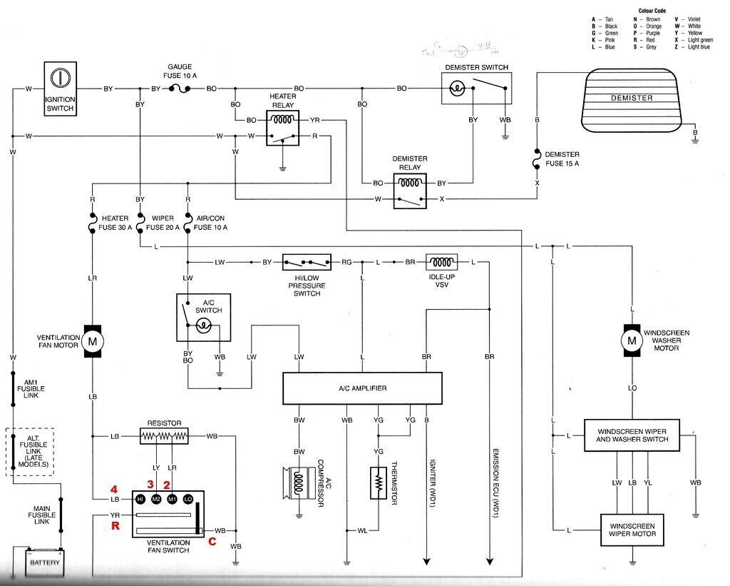
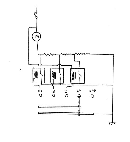
Circuit of the heating and ventilation systems.
The fan motor supply is fed from the battery
via the heater relay. Doing it this way avoids the high motor current being
switched by the ignition switch. Instead, the ignition switch only sees
the 200mA of the relay coil, and lasts a lot longer.
There is a 30A fuse for the motor. The
heater relay and 30A fuse are mounted just beside the cabin air intake.
Next to the 30A fuse is the 10A air conditioning fuse. To get at any of
these requires removing the glove box dash panel.
The fan switch has five positions; Off,
Low, second speed (2), third speed (3) , and High (4).
The switch and resistor is in the negative
side of the motor circuit. Thus, earthing the negative side of the motor
directly causes it to run at full speed. Speed is reduced when the motor
is earthed through one of the resistor tappings.
There are two common terminals for the switch. One (labelled C) is earthed, and is the common for the switch wiper. In "LO", the wiper makes no contact and the full resistance is in circuit. For the second speed (2), the last section of the resistor is shorted out, and for the third speed (3), the last two resistance sections are shorted out. When full speed (4) is selected, all resistance sections are shorted out, and the motor negative is directly earthed.
The other common terminal (labelled R) is for the heater relay. The earthed wiping contact also makes contact with this, completing the circuit for the relay coil. Note, however, that this contact is only connected to earth in the positions LO, M1, M2, and HI. In the off position it is not connected. So, we can see that the relay is actuated only when the ignition is on, and one of the fan speeds is selected.
A look at the Switch.
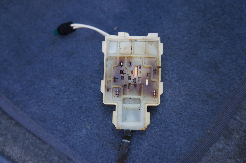
Note the overheated plastic.
To get at the switch involves removing
most of the dash panels. Once you've done that job as many times as I have,
it becomes second nature. Just watch out for the screws that are meant
to go in before panels go on top, when reassembling. There's one in the
upper corner behind the glove box, and another on the driver's side, just
under the instrument cluster.
The heater control panel just unclips
from the end opposite the clock.
Three screws release the heater control
assembly from the dash. You can't actually pull it out, unless you disconnect
the heater control cables, but you can lift it up enough to get at the
switch. The switch is secured by a clip accessed from the top side of the
heater control assembly. Lifting it slightly allows the fan switch to be
pushed back, and then it can be unplugged from the cable. Note that the
dial lamp for the heater controls is part of the switch, and the clear
plastic diffuser also needs to be unclipped to access it.
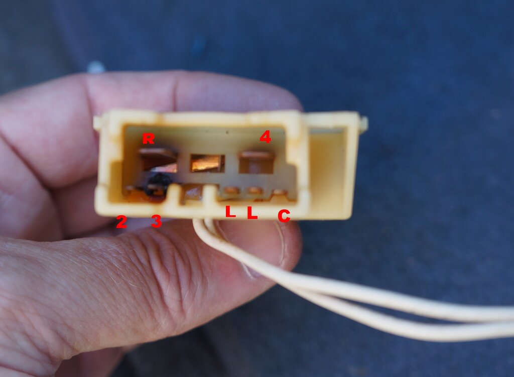
Contacts at back of switch. Note terminal 3 overheated. Terminals
L are for the heater control dial light and have no connection to the inside
of the switch.
Quite clearly, the construction of the switch was not up to carrying the motor current. For both switches, terminal 3 was badly overheated. This corresponds to the third speed, so carries more current than terminal 2, for the second speed. As for why the the 4th speed terminal, (terminal 4), was not overheated, notice that this terminal is much larger than the other terminals. Surprisingly, the other large terminal (R) is just for the relay coil. They would have been better to swap terminals 3 and R when the switch was designed.
A look on the internet showed new switches
available for $120. Ridiculous for such a simple part, and one of bad design.
Of course, I wasn't going down that path, especially knowing it would fail
again anyway.
Obviously, an electronic solution was
needed here, so the switch didn't need to handle the motor current. Two
obvious choices are to use relays, or MOSFET's, to switch the motor.
Next was to clean up and lubricate the
inside of the switch. This was quite salvageable, and the contacts were
functional enough to switch relay coils for a long time yet. Unfortunately,
the connector in the multi pin plug for terminal 3 was also overheated,
but it would be difficult to replace. However, 200mA of relay coil current
should not be problematic.
New Circuit.
Keeping with simplicity, I decided to
use relays. The relay contacts would switch the resistor tappings to earth,
and the switch would complete the relay coil circuit to earth. The relays
would be standard 12V automotive SPST types available from a multitude
of sources.
It's worth shopping around since they
varied in price from about $7 to around $21 each. I bought mine, along
with their bases, from Jaycar. The relays are cat. no. SY4068, and the
bases are SY4069. The bases have five connections with short wires attached,
but since the relays are only four pin, I removed the wire to the 5th connection.
The whole lot cost me about $42.
Three relays are the only parts required.
Next to the practical considerations. The resistor is mounted in the bottom of the fan housing, so that it is cooled by the fan. The relays would need to be located nearby. As it happens, there was space under the existing heater relay and fuses, so an aluminium panel was made up to mount the three new relays. This was secured under the existing relay block mounting screw.
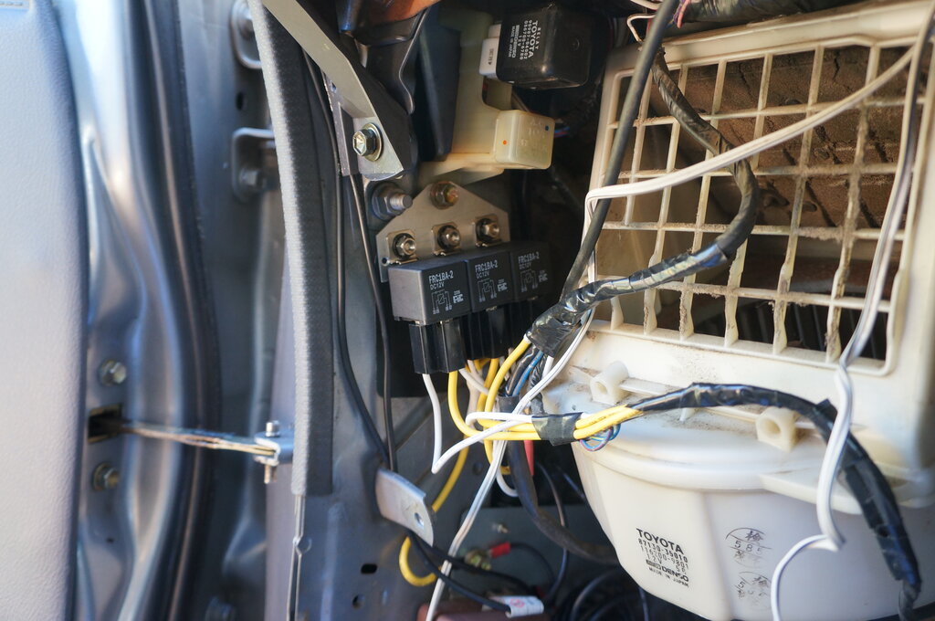
Three relays mounted under the existing relay and fuses. Wiring
harness at right runs down to the resistor.
You can see in the photo that I cut into the wiring harness where is passes around the cabin air intake. All the connections are available here. However, for neatness, I made the earth connection for the three relay contacts directly to the body - see the yellow wire running down to the bolt below the relays.
The common positive for the three relay coils was tapped into the thick blue/red wire which runs down to the fan motor. Next, the wiring harness to the resistor was cut at the blue/red wire. This is for 2nd speed (no relays are used for low speed, since the entire resistor is in circuit). The resistor end of this wire was connected to the non earthed contact of the left hand side relay. The switch end of this wire was connected to the coil of the same relay.
Then the blue/yellow wire was cut. It was connected the same way to the middle relay. This is for 3rd speed.
Finally, was the wiring for the high speed.
The relay on the right side was used for this. The wiring here is slightly
different, because in this position in the original circuit, the switch
is connected directly to the motor via the blue/black wire.
Looking at the circuit, there is a junction
of three blue/black wires - 1) from the motor, 2) to the resistor, and
3) to the switch. The switch needs to be isolated from the motor and resistor.
To do this, the wire to the switch was cut at the junction of the three
wires.
This junction is in the wiring harness
about 75mm past where the motor wires come out of the harness .
The relay coil wire was then connected
to the wire running to the switch, and the contact wire to the joined together
motor and resistor blue/black wires.
It was all a complete success, and worked perfectly. Now all the fan current is switched by 20A relays, and the switch should have an easy life.