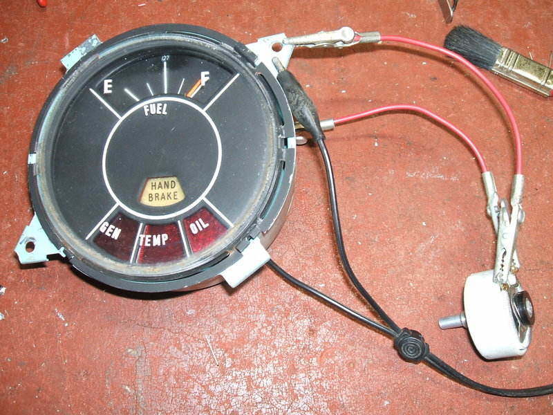
Repaired fuel gauge being tested. The rheostat simulates the petrol tank sender.
Repaired fuel gauge being tested. The rheostat simulates the petrol
tank sender.
When those in the vintage car world learn of my electrical background, it's natural to be asked various questions about automotive electrical systems, and to provide assistance in getting something to work properly.
Gauge always shows Empty.
One such interesting repair was a HD Holden
fuel gauge. As it turned out, there was a design fault which I'll get to
later. The problem as the owner described to me, was simply that the gauge
did not work, always showing "empty". He was suspecting the sender might
be faulty, and it was at this time I got involved.
The basic principle of a fuel gauge is
that the gauge is really an ammeter of one form or another, and it simply
measures current flowing through the fuel sender, which is really just
a rheostat.
For this fault, there can only be three
possibilities; 1) no 12V supply, 2) open circuit gauge, 3) open circuit
sender.
A simple test to start with is to disconnect
the fuel sender at the petrol tank, and see if there's any voltage coming
down the wire from the gauge. If there is, it means the supply and the
gauge are probably OK. In this situation, there wasn't any voltage.
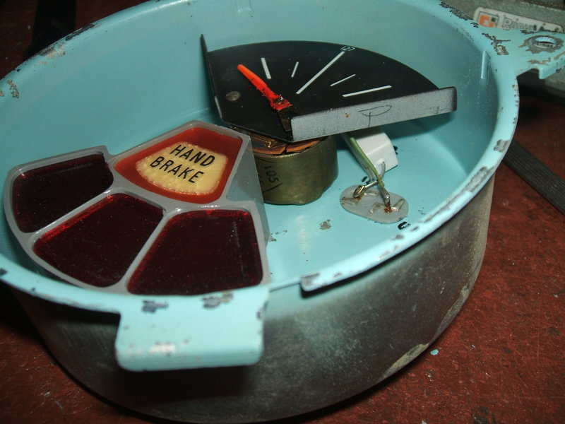
Now it was time to extract the gauge from
the dash. 12V was present at the "bat" terminal, but nothing at the "sender"
terminal. Obviously, the gauge was open circuit.
The two way connector at top left is for the sender and 12V connections.
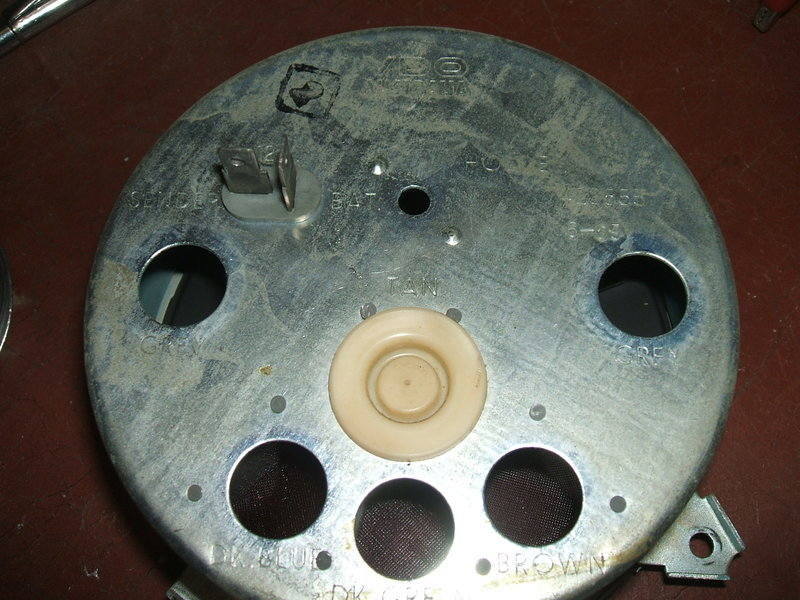
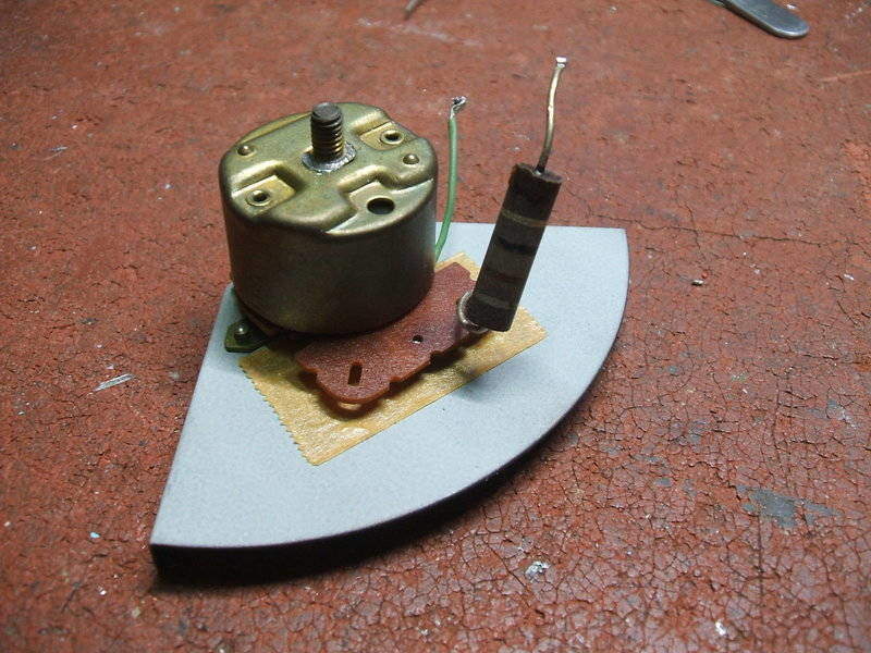
The face of the gauge is crimped on, but easily removed. Once open I could see a meter movement and a rather darkened 1W resistor.
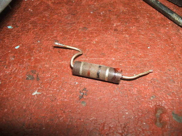
Open circuit resistor.
The question was, what is the value of
the resistor? It looked like 82 ohms, but I wasn't certain given
the body colour, and the fact that bands on a burned resistor are not always
their original colour.
I quick internet search brought up two
useful things; this resistor burning out is not uncommon, and the sender
is 30 ohms. However, I was sceptical of one forum's advice that the resistor
was 12 ohms.
At this point, a friend into old Holdens
came to the rescue because he had a working example of a similar gauge
from another model. It was indeed 82 ohms. I could imagine that it could
be interpreted as 12 ohms if it was read in the wrong direction, however.
It's 82 ohms, not 12 ohms as one forum suggests.
Dual Coil Meter.
If the gauge was just a simple ammeter,
it would work in laboratory conditions well enough. However, it must be
remembered that the car electrical system voltage fluctuates from around
12 to 14V. Thus, a simple ammeter would indicate a varying fuel level depending
on the engine revs and state of battery charge. Some cars have a voltage
regulator for the instruments to prevent this problem. In the Holden, there
is no such regulator - the gauge is simply fed with battery voltage of
whatever value that may be. So as to prevent voltage fluctuations affecting
the gauge, a special dual coil meter movement is used.
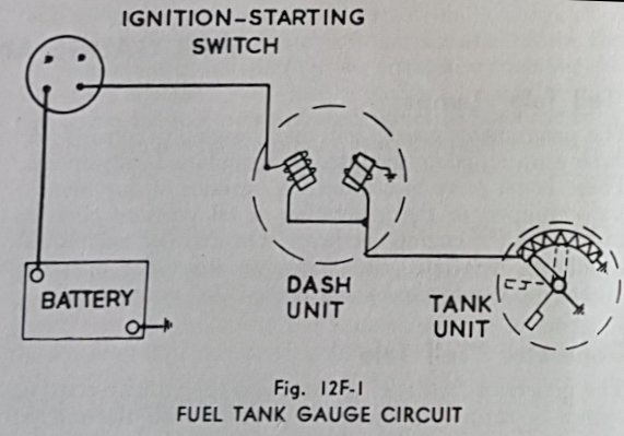
Simplified diagram of the fuel gauge circuit.
In essence, the meter's magnetic field
which drives the indicator needle is the combination of that from two coils.
The magnetic fields are such that they cancel each other out.
Looking at the above diagram, it can be
imagined that if the battery voltage rises, current through the left side
coil will increase, and so will its magnetic field, causing the needle
to deflect from its original position. However, the current in this coil
flows not only through the sender, but also to another coil. Therefore,
the magnetic field in this coil also increases, and because of its placement,
it starts to cancel out the field from the main coil. Thus, the needle
remains steady.
This is very simplified explanation, but
should help understand why it's made this way. Indeed, over an 11 to 14V
range, I found the reading did not fluctuate, once the gauge had been repaired.
In the above diagram, the resistor is
in series with the battery feed to the left side coil. Evidently, some
gauges made by another manufacture use a higher resistance coil instead
and don't include the resistor. The gauge I repaired with the resistor
is a VDO.
Repair of the Gauge.
The question now, was why did the resistor
burn out? Even though it was an IRC carbon resistor, low value examples
are usually very stable. If it was in the tens of k-ohms, it would have
been no surprise, but this was only 82 ohms.
Some further testing revealed we had a
design fault, and the resistor was being overloaded, but more of that later.
First thing was to confirm the resistor
value. The sender specifications were 30 ohms for a full tank, and 0 ohms
for an empty tank. This can be simulated with an ordinary rheostat - see
the first photo on this page. 82 ohms worked perfectly, with the gauge
showing an empty to full variation with the rheostat adjusted from 0 to
30 ohms. As a matter of curiosity, I tried 12 ohms. It too 'worked', but
the current was much higher, and could possibly damage the coil windings
over time - to say nothing of the fuel sender. At around half an
amp, the 12 ohm 1W resistor won't last very long either.
Because it was obvious that the 1W rating
was inadequate, I installed a 5W resistor. Short of the car's charging
system failing and the battery going open circuit, this new resistor can
never burn out again.
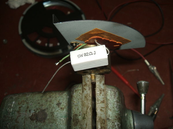
Unless the laws of physics change or the charging system fails,
this new 5W resistor cannot burn out.
The whole lot was then reinstalled in the gauge housing:
A Trap!
It is easy to assume that just the "bat"
and "sender" connections need to be used when testing the gauge. This is
not so, and one will think the gauge is still faulty after resistor replacement.
The
case of the gauge must be earthed! Unfortunately, there is no earth
wire running to the gauge as part of the instrument wiring, and unless
the gauge is screwed into the dash it won't work. When testing outside
the car, the negative must be connected to the case, as well as the substitute
sender.
Design Fault.
Some measurements made under varying operating
conditions show what the problem is.
| Sender Position | 12V Supply | 14.4V Supply |
| "Full" (30R) | 108mA (956mW) | 129mA (1.36W) |
| "Empty" (0R) | 127mA (1.32W) | 152mA (1.9W) |
The above table shows the resistor current
and power dissipation with 12V and 14.4V supplies, and with the petrol
tank full and empty.
One gets the impression that the designers
in the VDO laboratory only ever tested the resistor operating conditions
with a 12V power supply, and with an assumed full tank of petrol. In this
situation, the resistor is just within ratings. The worst case scenario
is with the battery charging and the tank near empty. Here, the dissipation
is almost double the rating!
From this, it could be assumed that those
owners who drove with a full tank all the time are less likely to have
their gauge fail.
It is true that resistors will survive
a degree of overload for some time, but as these cars are now over 50 years
old, we shouldn't be surprised at the failure. Replacement of the resistor
with a 5W type will always ensure it is always operating well within ratings.