One of the most misunderstood aspects of
the Model T is the ignition system.
The coils and timer system goes back to
the Quadricycle, with the power source being battery only, until the Models
N,R,S, which had the option of an accessory dynamo, and finally the T,
which introduced the flywheel magneto. With nearly 16 million Ts, and
thousands of the preceding models using this system, one would have to
be suspicious of claims of unreliability.
Being of such apparent simplicity, the
method of operation and initial adjustment is a trap for the unwary. Simply
assuming the coils are glorified door buzzers with a high voltage output,
leads so many owners into trouble. Left frustrated and unable to get good
results, a more familiar ignition system then gets installed. However,
with the understanding of some key points, and a methodical set up procedure,
the Ford ignition system is as effective and trouble free as any other.
Coil Rebuilding.
Unless they are new reproductions, coils
will need to be rebuilt before use. They may well buzz and produce a nice
fat spark, but this is just the start of the trap many fall into.
Firstly, the ninety odd year old internal
capacitor, being of wax paper construction, will be leaky. Not necessarily
leaky enough to prevent a spark being produced, but it will be leaky. This
leakage may increase with temperature and voltage input to the coil, further
compounding the problem. The end result is the output from the coil is
not consistent and not as high as it should be. In the extreme case, the
coil will buzz but be unable to produce a spark.
Secondly, the condition of the coil points
and their setting is important. Incorrect settings can indeed provide a
strong spark, but rough running is the likely result.
Some coils have open circuit high voltage
windings. These will still often produce a spark as the high voltage jumps
the break in the winding. However, not only is there a loss of high voltage
for the spark plug, but the continual arcing between the broken ends of
the winding will erode it away until the gap is so large that the coil
fails to produce an output.
Before rebuilding a coil, the resistance
of the secondary winding needs to be tested with an ohmmeter. Typically
it should be around 3000 ohms. While reproduction windings are available,
they are tricky to fit, and unless you have a set of the rarer coil types
used in the very early cars, its easier just to find another coil with
good windings.
How the coil works.
The door buzzer approach is only a simplistic
way of looking at coil operation. There is however, much more to it.
Basically, energy is stored in the soft iron core of the coil and released
at a controlled rate, through the high voltage winding and into the spark
plug. The capacitor controls how fast this energy is released.
The amount of energy stored in the iron
core is determined by how much current flows through the low voltage primary
winding, and for how long. These factors are largely determined by the
points adjustment and supply voltage.
First, let us examine the low voltage
side of the coil. When current from a battery or magneto is fed into the
coil, current flows through the primary winding of the coil. A magnetic
field thus builds up around the iron core.
This magnetic field does not reach its
maximum strength immediately, but takes a finite time, which is determined
by a number of things, one of which is the coil current. The higher the
current, the faster the magnetic field builds up.
If current is allowed to flow beyond the
time at which the maximum magnetic field has built up (a few milliseconds),
the core becomes saturated, and the energy is now wasted as heat. This
is why we sometimes see a coil where the pitch has oozed from the casing;
chances are the current was set too high.
The iron core has a secondary purpose
which is to attract the lower vibrator point, thus interrupting the circuit
before the core can become saturated.
Once the current is interrupted, the point
springs back, completes the circuit and the process starts again. This
happens about 300 times per second. Hence, the characteristic buzz.
The Capacitor.
With the sudden interruption of the current
when the points open, the energy stored in the iron core is rapidly released.
Because the magnetic field collapses faster than it took to build up, the
primary winding actually generates something much higher than the battery
or magneto voltage. In fact, its enough to arc across the points as they
open. This is the points arcing seen on a Ford coil with an open circuit
capacitor.
We can slow down the rate of magnetic
field collapse by connecting a capacitor across the points. The capacitor
absorbs the energy at a specific rate of time, and reduces the voltage
across the opening points to a non destructive level. Typically, this may
be around 300V when the coil is operating from a 6 volt battery. (Note
that this figure was measured with a particularly good coil and others
may differ!)
Needless to say, the value of capacitor
is important as it not only affects output voltage but also points life.
The capacity is 0.4 to 0.45 microfarads for KW coils and should be rated
for at least 400 volts working.
Unbeknown to most T owners who have attempted
to replace coil capacitors is another very important rating. This is the
dv/dt rating, which is the rate of voltage change over a specified time
period. Put simply, if the capacitor is forced to charge too quickly it
will overheat and fail.
The Ford coil requires a capacitor of
at least 600 volts per microsecond. That is, if you were to charge the
capacitor up to 600 volts in less than one microsecond, the rating would
be exceeded and it will eventually fail.
Ordinary polyester capacitors sold by
most component suppliers like Jaycar and Altronics, are rated at about
100 microvolts per second. This is why so many folk experience failed capacitors
when attempting to rebuild coils, even if the correct capacity and voltage
ratings have been used. Suitable replacements will be discussed later.
Unfortunately, most coils in the past have had completely unsuitable
capacitors installed by owners not familiar with coil operation. This is
one reason for the prolific amount of cars today fitted with distributor
ignition.
How is the Spark Plug
Voltage Produced?
Having produced our pulses of 300 odd
volts across the primary winding, simple transformer action is used to
step this up. A secondary winding of many more turns is wound over the
primary. The collapsing magnetic field will therefore induce a higher voltage,
the value of which is determined by the ratio of the number of primary
turns to the number of secondary turns. The primary winding of a typical
KW coil has 212 turns and the secondary winding has 16,600 turns. Thus
the turns ratio is 78:1. Now, what happens when the 300V is stepped up
78 times? The magical figure of 23,000 volts is produced; more than enough
to reliably jump the gap of a spark plug under compression.
The astute reader may wonder about coils
with an open circuit capacitor and why they fail to produce output. After
all, with much higher voltage across the points shouldnt this in turn
produce a greater spark plug voltage? In theory, yes, but when air ionises
and breaks down it forms an arc at those opening points. The voltage across
the points gap then drops considerably because an electrical arc is a conductor.
Most of those intending to rebuild their coils will be glad to know that the technical information presented so far is not actually necessary, but it does illustrate why it is necessary to rebuild original coils and with the correct capacitor.
Preparing the Coil
for Rebuild.
I find a scouring pad good for cleaning
the wood surface to get old dust and grime off it. If the coil has been
painted this could cause problems, if the paint has a conductive pigment.
Therefore, it should be removed from around the terminals and points mounting
nuts. PVA glue is ideal for repairing the wooden parts, if required.
To access the internals, it is first necessary
to remove the two or three panel pins at the bottom of the coil box. The
lid should just slide downwards, unless it has been stuck in position by
the pitch inside the box. If so, gently prying will usually release it.
In some cases its necessary to break apart the box but this isnt as drastic
as it sounds because it will usually come apart cleanly at the joins.
The messy part comes with removing the
pitch around the capacitor. The capacitor occupies the entire length of
the box on the left hand side. Immediately to its right is a strip of wood
or a piece of glass used to insulate it from the actual coil windings.
The old capacitor must of course be removed. Depending on the size of the
new capacitor, the insulating strip of wood or glass also needs to be removed.
It is no longer required when a new plastic bodied capacitor is installed.
Be careful not to damage the coil windings
with whatever implement is being used to dig them out. In the process,
pieces of pitch will fly everywhere and stick to everything. It is better
to chip out the pitch cold rather than to heat it for it will come out
in chunks rather than a gooey mess.
An easier way is to simply prise off the
side of the box next to the capacitor. The side should come off cleanly
at the finger joints, since it is not glued. Once the old capacitor is
out, the side can be replaced, using PVA glue to secure it.
As the capacitor is extracted, cut off
its two connecting wires close to the body; one at each end.
Removing the Nuts.
Next, remove the points assembly; this
involves removing all the nuts on the top of the coil. Unfortunately, removing
these nuts can be problematic because they are often rusted tight, particularly
on coils stored in less than optimum conditions. The nuts are available
from the usual parts suppliers, but unfortunately the screws are not, and
they are of an obscure thread. I use an equivalent diameter BA size brass
screw and nut as a replacement if the originals are damaged. Important
to note is that the only thing stopping the screw turning is a square shaped
chamfer under its head. If the screw is forced, this wears away the keyway
in the wood making the screw even looser. CRC and the like can sometimes
help free the nut, but often it has to be ground off. If the screw is one
with a connection to the internal wiring, the soldered joint inside will
often fail when the screw is forced when trying to undo a stubborn nut.
With early brass top coils, see that the
insulators are in good order, otherwise the points might be shorted out.
Capacitor Replacement.
As explained previously, there are very
few capacitors suitable for use in Ford coils. The original capacitor has
a value of 0.4 to 0.45 microfarads. The nearest value available today is
0.47 microfarads which is well within tolerance.
It is futile obtaining the capacitor from
any of the usual hobby type electronics part suppliers because it will
have insufficient dv/dt rating, and will eventually fail, no matter how
high the working voltage. While points capacitors used for distributor
ignition systems may look enticing, they have inadequate dv/dt rating.
Electrolytic capacitors are the worst possible type one could choose. Not
only are they for DC only, but are completely unsuitable for pulse circuits
and will fail immediately.
There are only a few kinds of capacitor
which are suitable. The first is a polypropylene type available from Farnell
and other specialised suppliers. However, its dimensions make it awkward
to fit inside the box and it is rather expensive.
The best type of capacitor is a Sprague
Orange Drop which is available from several Model T parts suppliers;
in particular Langs and Snyders.
Unfortunately, some suppliers are still selling ordinary polyester capacitors
which fail. Another type was also available direct from the no longer extant
Fun Projects. Not only do these easily fit in the coil box, but they are
very inexpensive; around $2.00 each.
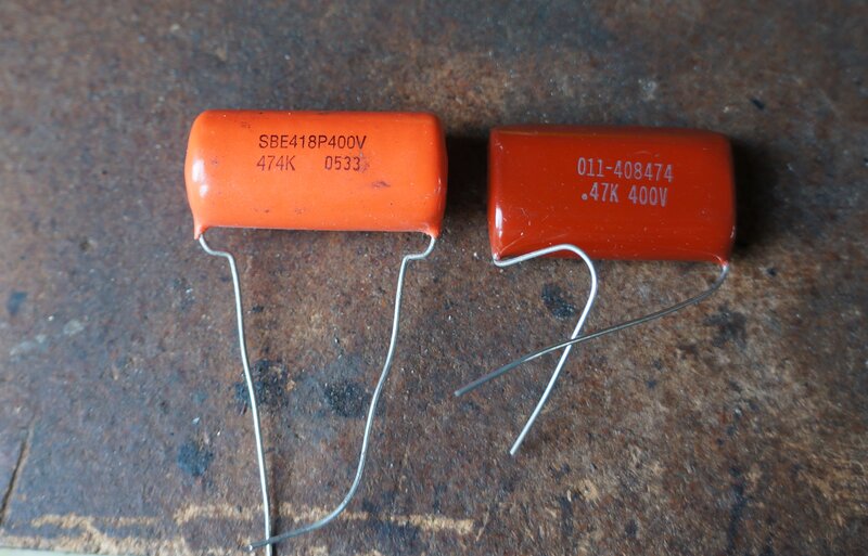
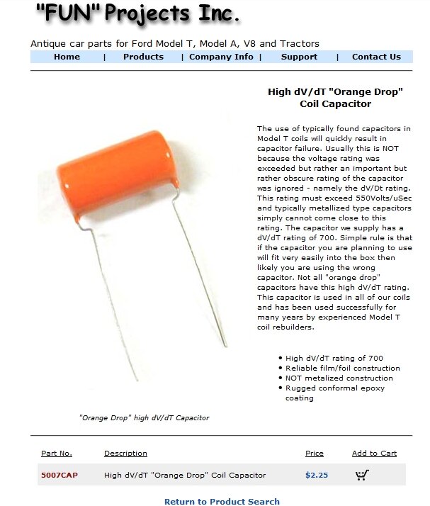
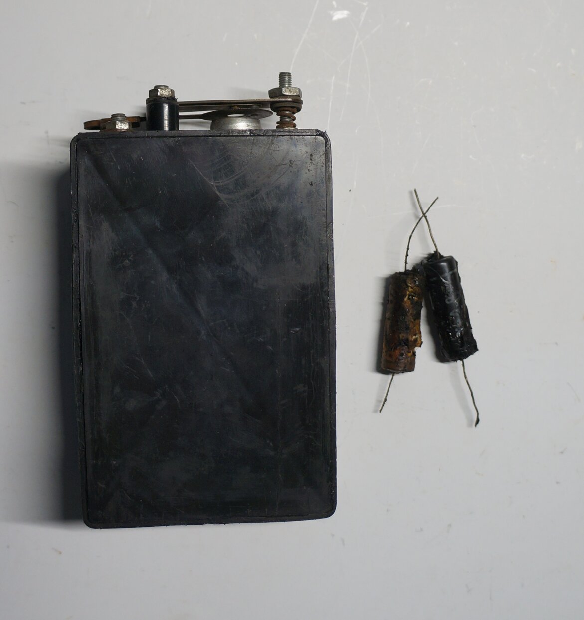
Correct capacitors. At left is the Sprague type with a dv/dt of
700v/us, and at right is a type sourced by Fun Projects with a dv/dt rating
of 1700V/us.
The story of why it is essential to use
the correct capacitor was described further on the Fun Projects site. Essentially,
the capacitor has to be able to tolerate a very high voltage within a very
short time.
Postcript 2022: Fun Projects no
longer exists, but the correct capacitors are still available from Langs
and Snyders.
Again, I need to emphasise incorrect capacitors
will end in frustration. Provided the correct type is used, the coils will
happily operate from a 30V magneto for a lifetime, without the capacitor
failing.
Installation is simply a matter or connecting
its leads to the wires cut off the old capacitor. The joints should be
twisted before soldering, given the vibration the connections will be subjected
to. I dont advise re potting the capacitor until the coil is tested, just
in case there are other faults.
Points Checking and
Replacement.
Because the coil box wood is soft, it
may have been noticed that the two cylindrical spacers used to support
the upper point have sunk into the wood, likewise the attachment of the
lower point bridge.
Leaving things in that condition will
prevent correct point alignment, but one can simply pack up the depression
in the wood with washers to restore the original level.
The screws and nuts need to be cleaned
of rust because this can result in non operation of the coil.
The point gap adjustment nut (the one
everyone fiddles with when they shouldnt) has fibre washers to separate
the spring from the upper contact.
If they have crumbled away they will need
replacement. The fibre washer is not strictly necessary with the wooden
top coils, and a steel or brass one can be used instead. Brass top coils
do require the fibre washers, otherwise the top of the coil will be connected
to the upper point and short out.
Old points can be reused provided pitting
is not severe and most of the contact surface is present. It is possible
to clean them up for a new lease of life, but any filing must be done as
squarely as possible, otherwise the full contact will not be made, resulting
in overheating and erosion of the small part that does make contact.
Given that new points are inexpensive,
it is worth replacing them when rebuilding a coil unless the old ones are
in excellent condition. New points are available from the usual Model T
parts suppliers, as are other parts for the coils.
Installing the Points.
Replacing the points is straightforward
enough, but if the screws securing them to the box keep turning or need
replacement, now is the time to deal with it. These screws are of an obscure
thread but replacement nuts are available. If authenticity is not important
they can be re threaded or replaced with something more convenient.
When screwing down the nuts, see that
the points are set squarely. This is done by holding down the upper contact,
against the lower contact and seeing that the two contacts are fully touching.
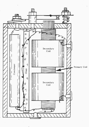
Next, the points gap adjusting nut can
be set (point C in the diagram). To do this, hold down the lower vibrator
contact until it touches the iron core. Using a feeler gauge, screw down
the points adjusting nut until the upper vibrator contact has a 0.031
clearance.
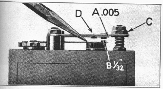
The cushion spring is the final static
adjustment. Here, with the lower contact held against the core, there needs
to be about 0.005 between the cushion spring and the upper vibrator, shown
at point A. This is achieved by slightly bending the upper vibrator which
can be done by gently tapping on point D.
Note that the points are horizontal with
respect to the coil casing. Often, the spacers for the upper contact have
sunk into the soft wood. Use 5mm washers to restore the correct spacing.
If the lower contact cannot be made horizontal, chances are the iron core
has migrated upwards. One way to restore its correct position is to heat
the coil by passing a few amps through the primary winding, and then pushing
the core back.
Unless the coil geometry is correct to
start with, it will be very difficult to adjust it for correct operation.
Once the points have been statically set it is now time to set the current and check for double sparking. This is an area where many run into trouble, again resulting in frustration and discarding of the original ignition system. Suitable test apparatus is required, and there is no shortcut.
Adjusting the Coils.
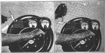
Until recently, the best method was to
use a hand cranked coil tester. The procedure is outlined in the Ford Service
Manual, which every T owner should have, so I wont go into detail here,
except to say that the machine is cranked at sufficient speed to show 6
volts. Then, the current of the coil is set to draw 1.3 amps. Coil current
is set by means of adjusting the tension of the lower vibrator point. One
way of doing this is to use a pair of long nose pliers and bend the lower
contact bridge up to increase current or down to decrease it. The
service manual shows a small hammer being used for the same purpose. A
small portable tester, operating on similar principles, was once made by
Fun Projects, and was called the "Strobo Spark". It is no longer available.
Eliminating the Double
Sparking.
There should be 16 evenly spaced individual
sparks around the spark ring of the coil tester. If there are groups of
multiple sparks then the cushion spring tension needs to be corrected by
bending the upper vibrator point near where the cushion spring rivet is.
Again, the procedure is outlined in the service manual. The important point
here is that if this is not checked, rough running on magneto is a possible
result.
However, adjusting the coils by means
of a hand cranked, or other mechanical tester is now obsolete. The main
limitation is that it cannot display coil firing time. This means that
while the multiple sparking can be adjusted out, there is no guarantee
that the coils will each take the exact time to fire as the others in the
set. Nowadays, electronic methods are preferred.
Electronic Testing.
In view of recent technology, the superior
method of electronic testing is now possible. This is an article in itself
which can be read here.
The Model T owner is strongly advised
to investigate the ECCT; the Electronically
Cranked Coil Tester. This device allows coils to be set so they all
fire equally, and without multiple sparking. For the technical user, the
instrument provides a detailed coil analysis. Furthermore, those with a
magneto can properly test that too. All in all, it's a comprehensive Model
T ignition diagnostic tool.
"Buzz Box" Coil Testers.
Familiar to many, these simply consist
of the coil being placed into a jig which connects it to a battery via
an ammeter. A spark gap is provided to load the coil and simulate a spark
plug. These devices have their place and can be useful, provided their
limitations are understood. This method of testing will not allow the user
to eliminate multiple sparking, nor can equal firing time to be adjusted.
In short, this kind of tester can get coils going in an emergency, or be
used as a basic go/ no-go test, but it is important to remember that the
car's performance is unlikley to be optimum as a result of adjusting coils
this way.
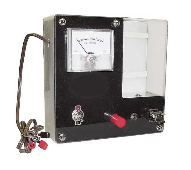
Buzz Box coil tester. Not recommended for accurate adjustment, but
will get the car drivable.
Note that for those who have ideas of using
a 12V battery with this kind of coil tester, the current readings are completely
different, and setting to 1.3A at 12V will result in short point life as
well as difficult magneto operation.
When a coil is run at more than 6V, the
current automatically reduces but the power input to the coil remains roughly
the same, although it is not a completely linear relationship. This is
one reason the 30V AC from the magneto does not overload the coil as might
be first thought.
The source of 6V for the coil tester should
be a battery of reasonable capacity, otherwise the voltage will drop under
load and give erroneous results. For those who dont have a 6V car
battery, a new 6V alkaline lantern battery (of the type that fits Dolphin
or Big Jim torches) can be used providing the tests are kept short. Incidentally,
such a battery has enough capacity to run Ford coils and get you home if
your magneto or normal car battery has failed.
Coil still Faulty?
In some instances a rebuilt coil fails
to work. There are several things to check here. Most common is rusty nuts
preventing good connection between the point assembly and internal wiring.
One instance I encountered was where the new points looked perfect but
one of the actual points was found to be insulated from the vibrator spring.
It had simply not been riveted tightly during assembly. Dry or broken solder
joints to the points mounting screws are another common fault. These should
be inspected closely when installing the new capacitor.
Another possible problem is the connections
to the three brass terminals on the side of the box. Two problems can happen
here. One is with the soldered joints. Sometimes the enamel was not completely
stripped from the winding wire when the coil was manufactured. While the
solder looks like it has completely covered the terminal, removing it will
show up if this is the problem. Ensure the solder takes to the actual wire
when resoldering these terminals. Another fault is often really to do with
the coil box in the car and how the coils fit into it. It can be that the
contacts simply do not make good contact with the coil terminals because
of warpage of wood, etc. This is often the cause of "it works in the tester
but not always in the car".
Open circuit secondary windings are possible
but not common. Unfortunately, some open circuit secondaries have been
the result of over zealous capacitor removal. It's a very fine wire, so
be careful.
Battery Only Operation.
Operating conditions for coils are quite
different on DC (battery) and AC (magneto), and the multiple sparking is
less of a problem with DC. This gives rise to the rough running on magneto
but smooth on battery phenomenon when the coils havent been set up correctly.
A word on battery versus magneto operation
would be pertinent at this point. Suffice to say, with attention paid to
a few points, battery operation is satisfactory, and one should not feel
unable to use the Ford coils if the car does not have a working magneto.
Conveniently, the ideal operating voltage on DC is between 6 and 12V. As
an example of performance, 75+ km/h can often be achieved in a car with
a 6 volt electrical system and no magneto. For 6V operation, attention
must be paid to the initial timing otherwise high speed performance will
drop off. As it was, cars in the U.S. were set with an initial timing of
15 degrees ATDC with the timing lever fully retarded. This was done to
prevent kick back when starting on magneto. In Australia, with our RHD
cars, it is not clear what the initial timing was set to; whether it was
also 15 degrees or not. In practice, Australian cars are set with a timing
of about 2 degrees ATDC. The reason for this discrepancy is that there
is no timing gauge tool for setting the timing on RHD cars, and just after
top dead centre is the logical firing point at full retard - this gives
the greatest range of timing control without the risk of kick back when
starting. As it turns out, with only 2 degrees initial timing, there is
enough advance available for good high speed operation. So, for those using
6V only for their coils, the initial timing should be checked to ensure
optimum performance.
Migration of the contact material from
one point to another has been claimed to be a problem with DC operation,
with the result being one point loses material to the other. It has to
be questioned under what circumstances these claims have been made, because
my observations are that on 6V it occurs at an insignificant rate, probably
on par with magneto operation, but is more prevalent on 12V. Even then,
it is so gradual as to be practically irrelevant, and this has been proven
by a number of cars in the club. At this point in time, I have covered
nearly 30,000km with my original coil points running on 6V. They are still
in excellent condition.
Re-potting the Capacitor.
If all has gone to plan, and the coil
is now working and set correctly, the capacitor needs to be secured. One
can re use the old pitch by melting the pieces in a tin can over a weak
blowtorch flame. However, there will not be enough to fill the entire void
unless one has saved the pitch from other defective coils, but it is usually
enough to secure the newer, smaller capacitor. Another method is to use
expanding foam. This can easily be cut away with a knife if repairs have
to be made in the future, but is quite rigid when set.
Provided the coil restoration has been
done correctly, they should be faultless for many years, with possibly
a check on a coil tester every few years to see that contact adjustment
is still optimum. There have not been any reports of the proper high dv/dt
capacitors failing.
Plastic Coils.
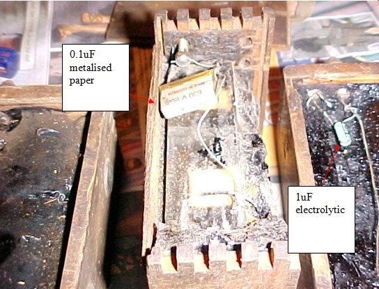
Plastic coil with two kinds of capacitor that may be found inside.
Information on these coils is non-existant.
They appear to be still manufactured. What I have been able to determine
is that the capacitor value is too low at 0.1uF. Primary coil inductance
is less than the wooden coils, and the peak current is higher.
To use these in your Model T, the capacitor
needs to be replaced with the correct 0.47uF high dv/dt type. It would
appear these coils are designed for 6V operation. To get rid of double
sparking, when setting these coils on the ECCT, it seems best to adjust
for a shorter firing time; about 3 or 4 degrees earlier. (Note that the
ECCT operates at 12V).
In terms of construction, these coils
are very good - except of course the capacitor is the usual weak point,
being the wrong type. However, because they have different characteristics
to the wooden coils, they should not be mixed. The coil set in a car should
either be all plastic or all wood; not a mixture of types. I have no experience
with plastic coils operating from a magneto.
Replacing the capacitor is easier than
the wooden types, since it is smaller. Also, the plastic doesn't come apart
or warp. The lid is secured simply by using the hot pitch as an adhesive
when the coils were assembled. After replacing the capacitor, the lid can
be secured by using silicone sealant around the edges and smeared over
the pitch.