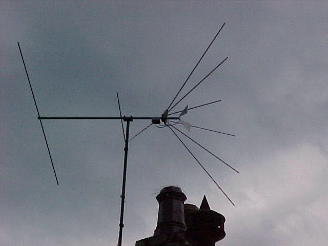
After many experiments and a lot of work, my Fan aerial is up and providing perfect pictures on both UHF and VHF.
After many experiments and a lot of work, my Fan aerial is up and
providing perfect pictures on both UHF and VHF.
My construction is largely based on an Radio, Television & Hobbies article first published in December 1956 and updated in November 1958. It's one of those projects that had stuck in my mind for years and finally upon re reading some 1950's TV articles I decided to build it. I'd known of the Fan (or Conical) type design for years of course but a few things surprised me about it. Why did it suddenly vanish in Australia after about 1959? Was there something wrong with the design? I have seen only one partially surviving example in Australia (a Channel Master 313) but that's all.
Background.
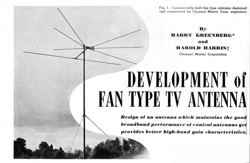
From "Radio & Television News", May 1950.
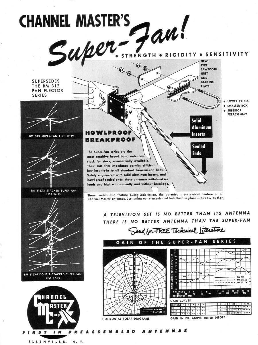
The Fan aerial design came from Channel Master in the U.S., with development starting in late 1949. It was for many years there, the most popular TV aerial design. It was simple, cheap, and has a fairly flat response across the VHF band. In May 1950 we see one of the first ads; their model 313 "Super Fan" which remained in production for about 10 years.
One of the first advertisements, "Radio & Television News", May 1950.
The Channel Master Super Fan was available
in Australia with the start of TV in 1956. By then, a few mechanical improvements
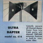
had resulted in it becoming the 313A. Back in the U.S., one could convert
the 313 to also work on UHF by means of the 414 "Ultra Dapter", or one
could just buy a complete 413 aerial instead.
Of course, most other aerial manufacturers
copied the design and it is seen in catalogs, such as those of Radio Shack
until the early 1970's, but in Australia the design had been long obsolete.
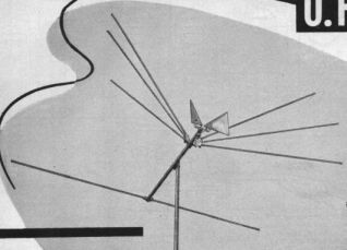
This JFD Jetenna 383 is typical of VHF/UHF combined aerials. The
bowtie elements and a diplexer are added to the front of the VHF dipole.
How does it work?
Operation is simple. It is an improvement
on a standard low band dipole with reflector. An ordinary dipole happens
to respond not only to its designed frequency, but also the the third harmonic.
This is how the one dipole covers both bands 1 and 3. For example, Ch.
2 on 63Mc/s x 3 = 189Mc/s which is pretty much in the middle of Ch's. 7-10.
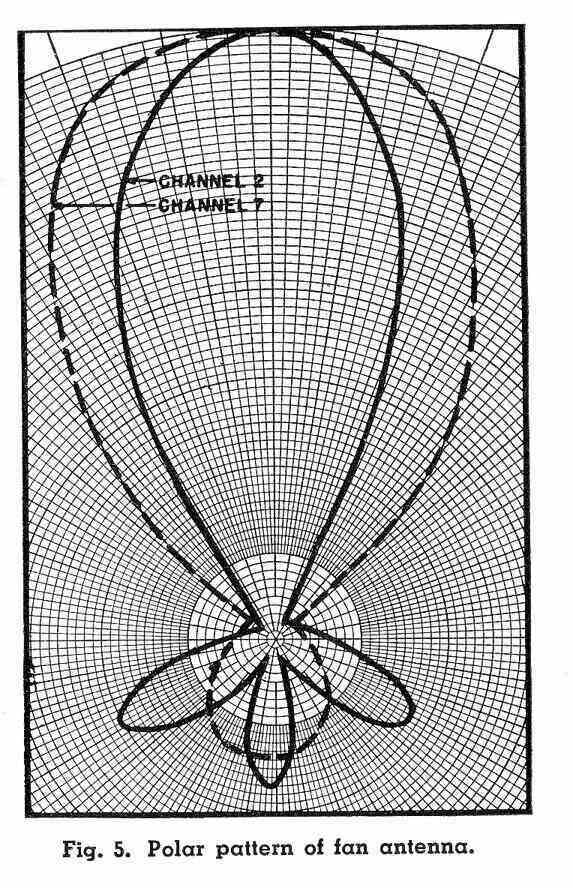
By fanning the dipole at about 40 degrees, an improvement in bandwidth
over a straight dipole is obtained. However, while the dipole works at
three times the fundamental frequency, the directional properties are poor,
with two lobes off to the sides. By bringing the elements forward into
the "V" formation, the lobes are brought together as one.
While I haven't seen any commercial examples
with it, RTVH&H included a reflector for the high band channels, which
they claimed did make a measurable, although not huge, difference.
Where UHF reception is added, an ordinary
bowtie arrangement is used, and makes use of the VHF elements as a reflector.
A diplexer is required to combine the two signals, or separate transmission
lines need to be run to the receiver.
Building the RTV&H design.
I was slightly hesitant to believe that
such a simple aerial would work in my area, about 80km from Sydney's TV
transmitters at Gore Hill. However, looking at the published data courtesy
of Channel Master, it appeared that the gain wasn't that low; in fact no
lower than many modern commercial types. And, there was mention of someone
in Kiama getting good results, in the follow up RTVH&H article. So,
that settled it! One problem of course was that it was only a VHF design,
which would mean having to keep the separate UHF aerial for Ch. 28 and
31. But, I remembered some of the UHF articles in my 1950's American magazines,
and some vague mention of existing VHF aerials working on UHF in good signal
areas. Following this up revealed more than I'd hoped for. The Fan aerials
could be fitted with UHF bowtie elements, and these were available as an
optional accessory. Again, the published figures of gain didn't look too
bad. In any case, if the UHF bit didn't work out, I could still use the
existing UHF aerial and diplexer.
Modifications.
One of the aspects of the RTVH design
that caused a lot of thought was that they'd used brass tubing for the
elements, and the central insulator was a hardwood block. The problem was
in the mounting of the elements to the block. Brass could be soldered,
but as I was going to use aluminium tubing this wouldn't be possible with
the design of their brackets. So, a major rethink was in order. I studied
the commercial designs and based mine on these. While commercial concerns
had the luxury of moulded plastic and aluminium, I was relegated to a simpler
kind of construction. After a lot of thought, I came up with making the
central insulator from pieces of bakelite laminated together, and the six
dipole elements could be attached by small panels of aluminium bent forward
at 35 degrees.
Close up of the bakelite insulator and mounting for the six elements.
Bolts pass through the bakelite into the boom to prevent twisting.
I used 25mm tubing for the boom and 12.5mm
for all the elements; these being consistent with commercial practice.
The tubing was easily obtained at Bunnings. I did use some stainless steel
screws and nuts, but experience in my locality is that nickel plated brass
work quite well with aluminium. I would not use that combination in a coastal
area however.
An ordinary tube cutter made a professional
job of all the cutting, but one thing which was tricky was to get the holes
along the boom straight. For, if they aren't, the reflectors won't be parallel
with each other or the dipoles. The way to do this is to rule a line along
each side of the boom and drill each side separately; not to drill from
one side and out the other.
First tests.
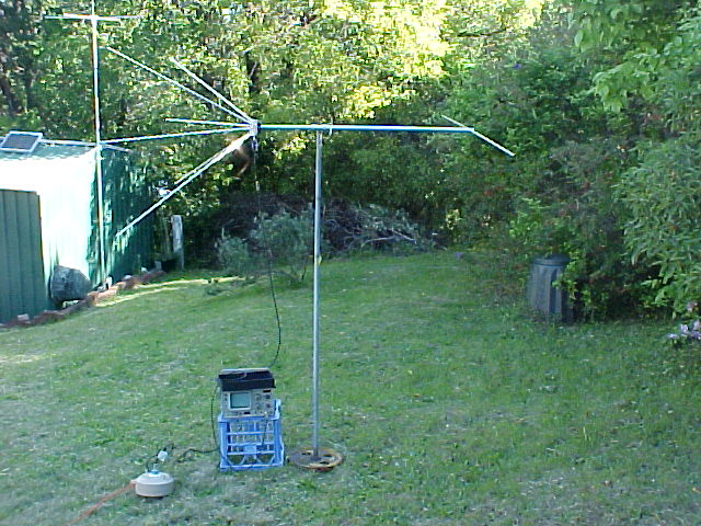
In the backyard with spectrum analyser for the initial testing.
First impressions on VHF were very good.
With the aerial mounted on a 2m high portable mast in the backyard, all
VHF channels came in with ample strength. What was particularly pleasing
was how level the digital channels were. It seemed the 'flat response'
of the Fan really was true. Connected to a portable television, the signal
was free of ghosting. It was also pleasing to see the FM signals coming
in strongly; this meant I'd not require a separate aerial for those.
On UHF things were bad. In fact, SBS 28
and TSN 31 were barely visible. However, the aerial wasn't far above ground
level and it had the neighbours house between it and the distant Gore Hill
transmitters. Even so, there was no way this aerial would be usable for
UHF as it was. I would have to add the UHF dipole.
Adding UHF.
This was where I was on my own, for although
RTV&H had provided dimensions for the VHF fan, I had nothing to go
on for the UHF section. Careful examination of advertisements showed a
UHF bowtie mounted in front of the VHF dipole. Some technical descriptions
indicated the VHF dipole acted as a reflector. From this, and the
pictures we could see the bowtie would be angled forward the same amount
as the VHF dipole. The distance between the two wasn't stated, but that
would be easy enough to test with a field strength meter to find the optimum.
What had me more curious was how to design the UHF dipole.
I would love to have known the dimensions of this!
I could not find any literature as to the
"how" of UHF bowtie design. All I knew was that the principle was the same
as fanning the VHF elements. I thus reasoned that the end to end length
must therefore be half a wavelength at the lowest channel. There were vague
references to "16 inches" in one article but that didn't sound very precise,
and precision is important for UHF, where millimetres make a difference.
I remembered Silicon Chip had done a UHF bowtie aerial project in the mid
1990's. Although, frustratingly, this article didn't explain how it was
designed, it did give me a set of dimensions. So, I made up a bowtie accordingly,
but with the elements bent forward as per the VHF section. I used a piece
of Lexan for the centre insulator.
I tried it as it was on its own and was
able to get quite reasonable UHF pictures with no reflector, so it looked
promising enough to continue. Next step was to try it in front of the VHF
elements. Here, a measurable improvement was obtained, peaking at about
13cm from the VHF dipole. I wasn't really surprised at the distance; it's
pretty much a quarter wavelength for the band 4 UHF channels.
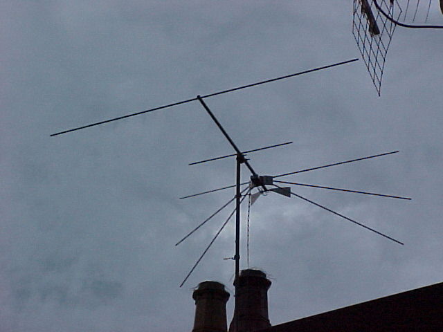
The UHF bowtie can be seen at the front of the completed aerial.
Next step was to make a proper mechanical
job of it, so I attached a 13cm length of aluminium tubing to the front
of the VHF aerial and then mounted the UHF elements on this.
In retrospect, I could have used a longer
one section boom without the join, but I wasn't convinced of the UHF performance
at the start of the project.
With the aerial set up on the portable
mast in the front yard, with only a hedge now blocking the signal, it was
possible to get almost 1mV on UHF. Things were looking good, but I wanted
to use one transmission line.
The Diplexer.
As both dipoles are balanced and I wanted
to use one length of 300 ohm ribbon down to the house, it was obvious I'd
need a 300 ohm diplexer. But, such things have not existed for a long time,
and especially in Australia where the use of ribbon on UHF had always been
discouraged. Again with nothing to go on, a fair bit of experiment was
called for and I almost gave up with the idea because of poor results.
I had seen an article in Radio Electronics
in the mid 60's for a homemade 300 ohm diplexer and so constructed it.
Alas, it was a failure! Problem was that the UHF dipole was sucking out
much of the VHF signal. There didn't seem to be enough isolation between
the two dipoles. Looking closer into this I could see what was probably
happening.
For one thing, the UHF bowtie does have
a response at VHF, and in fact provides almost snow free pictures, even
at my distance! The fact that the UHF dipole is placed more forward than
the VHF one would mean a phase difference in received signal, and thus
the probability of some cancellation if the phase was subtractive.
While I'm normally against the idea of
using a splitter to combine aerials, I did try it here in view of the good
isolation between ports. But again, there was loss of signal, with UHF
only 400uV. I tried other methods of combining without a diplexer but always
ran into problems.
The choices I was left with now were:
1) make a 300 ohm diplexer work, 2) run two transmission lines, 3) have
a masthead amplifier with separate VHF and UHF inputs up at the aerial.
Using a masthead amplifier would be expensive; they cost about $60. I was
almost going to go with the two transmission line option but decided to
have a closer look at a commercially made diplexer first. This had two
300 ohm inputs and a 75 ohm output. The main difference between it and
my previous attempt was that the UHF dipole isolating condensers were 3pF
instead of 10pF. So, with a bit of scepticism of such a low value passing
enough signal I tried it, and that was it! Barely any attenuation on either
VHF or UHF.
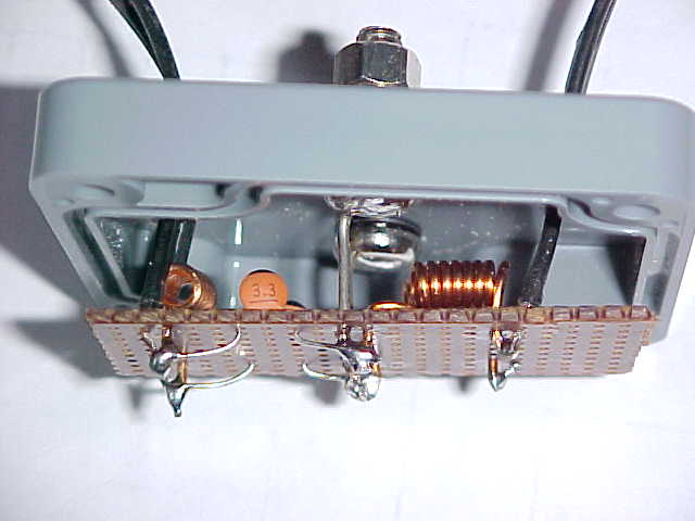
Inside of homemade diplexer. Parts were mounted on a scrap of matrix
board and enclosed in a weatherproof box.
Thus encouraged, I mounted the diplexer circuit in a plastic box which in turn was mounted under an aluminium enclosure to keep the UV off the plastic. A clamp then was made to secure this just behind the VHF dipole.
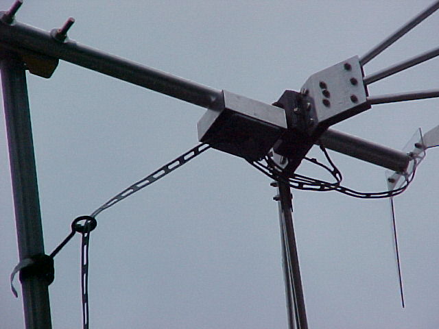
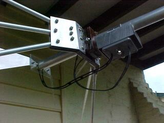
This shows how the diplexer is mounted to the boom and connected
to the dipoles and transmission line.
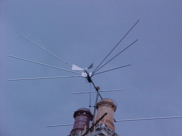
At last the aerial was complete and could be mounted up on the mast.
Rear view of Fan aerial pointed at Gore Hill. In the top right of
the pic is the reflector for the UHF aerial pointed at Knight's Hill.
The last part of this whole project was
to feed the signal into the house distribution system. This took a bit
of experimentation but the end result was the best TV pictures I've had
in 15 years.
I have a six way splitter feeding various
rooms, and as can be imagined it has fairly high attenuation; about 10dB
per port. Then in some rooms may be a 3 or 4 way splitter to feed the various
VCR's and TV's. With cable losses added to that we can say about 15-20dB
is lost along the way. So, a lot of amplification is needed prior to splitting.
I also have Knight's Hill UHF signals fed into the system. And here is
the opportunity for a multitude of problems if it's not done correctly.
A masthead or distribution amplifier is
a wideband design, operating from about 45Mc/s to 850Mc/s. To flatly amplify
this bandwidth with 30dB gain is quite a task and there is a risk of intermodulation
distortion. Think of everything between those two frequency limits being
fed into a high gain amplifier. Non linearities will see to it that the
signals will to some degree mix and create new signals; those are the ones
that cause patterning across the screen. The higher the gain, the worse
the problem.
The way around this is to amplify as narrow
a band as possible. In my set up, I require separate amplifiers for Gore
Hill VHF, Gore Hill UHF, Knight's Hill UHF, and FM. FM is the worst culprit
if it gets into the TV amplifiers, so here the FM filter must be in circuit.
Postscript August 2025.
This aerial has been up since Xmas 2010.
It's fared very well, with some maintenance required - largely because
of cockatoo damage. One of the top fan elements was bent by a cockatoo,
so was replaced. The reflector now has additional brackets securing it
to the boom. Again, cockatoos and also wind caused the boom holes to enlarge
slightly as the reflector moved about. The UHF dipole insulator broke during
strong wind - the sunlight had weakened it. Its transmission line to the
diplexer was also damaged by cockatoos. The 300 ohm transmission line down
to the house was replaced with a heavier duty foam type, since the original
had poor UV resistance and had badly cracked.
Analog transmissions ceased on December
3rd 2013, so the UHF dipole has not been used since then, and neither has
the band 1 reception capability (Ch. 2). The digital transmissions are
all in band 3.
In theory, it should be possible to build
a smaller aerial operating for only band 3, using the same principles.
However, the world is now a very different place than it was in 2013, and
it looks like free to air TV will soon be a thing of the past, as viewers
migrate to internet streaming instead.