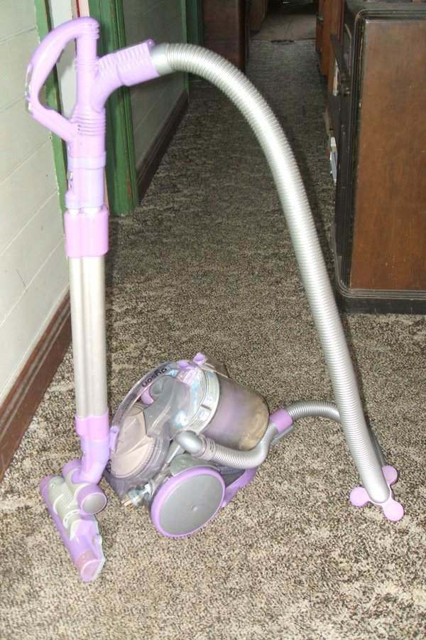
Dyson would consider this particular DC05 to be well past its use-by date but I keep finding ways to keep it going.
There has been a lot of fanfare with Dyson
products each time they are released. They stand out because of their unusual
design. However, from what I have experienced and researched, not is all
as it seems.
Product support turns out to be very poor,
and parts become unavailable after a short time - assuming they were available
in the first place. It seems to be a case of wanting you to replace rather
than repair.
The plastic used for the DC05 is a fire
hazard as will be shown later. Furthermore, there was a recall of the DC05
in 2010 after the handle came apart in some units exposing live connections.
I find the instructions for the DC05 very
poor, not really telling you anything about the vacuum cleaner itself.
Dyson would consider this particular DC05 to be well past its use-by
date but I keep finding ways to keep it going.
The DC05 came in two versions, the base model, and the Motorhead model, which is the one I have. In this, the vacuum head contains a motorised brush which can be switched off for smooth floors, or on for carpets. A third switch setting runs the brush at reduced speed and switches off the suction. This is for the application of "Zorb" - a carpet dry cleaning powder unique to Dyson. This is poured over the carpet and brushed in using the Motorhead.
My Dyson DC05 appeared in 2010, when it
was given to me by an HRSA member who found it in a council clean up campaign.
Knowing how expensive they were, I was rather pleased to become its new
owner. It had been well used with both HEPA filters completely blocked.
By the look of it, the DC05 had been used to clean up after house renovations
- it looked like gyprock powder in the filters. The fault was the motor.
Initially, I replaced the brushes but joy was short lived - the commutator
was in poor condition and I suspect damaged windings. The motors are available
on ebay, and after learning there were two types, I ordered the Panasonic
type which is what was in my machine. The two kinds are not interchangeable.
I also ordered new HEPA filters.
Performance was astounding! I had never
seen a vacuum cleaner perform so well, and I could see the Dyson hype was
justified. To me, no other vacuum cleaner would ever be acceptable again.
Motorhead Repair.
After a few years, problems developed
with the Motorhead brush drive. By July 2017, the belt had lost teeth and
the motor pulley was wearing down. The pulley is made of plastic which
appeared rather soft and not designed to last in this application. Unfortunately,
neither part was available from Dyson or Dyson parts suppliers.
In fact, it appears that these parts were
never actually available! It is bizarre that something like the brush belt
was
not available. Instead, one is expected to purchase a complete new Motorhead.
New Belt.
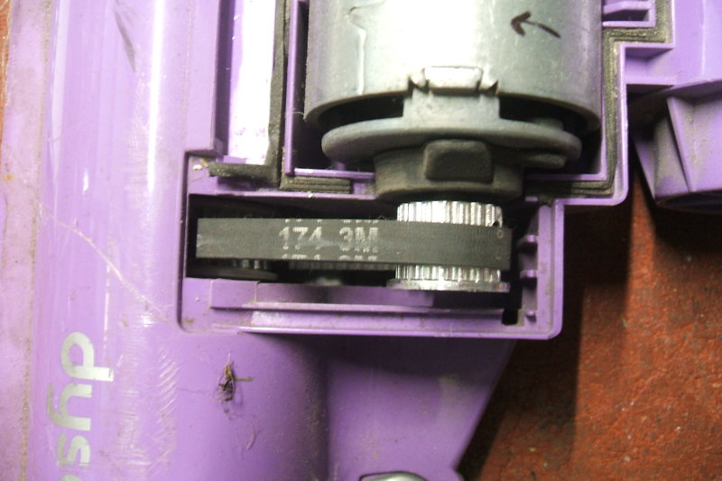
The belt is a toothed type commonly used
in laser printers and similar items. It would seem that it should be a
generic part, and indeed, many ebay sellers exist for such things. By measuring
the distance between the belt teeth, it was determined
that the pitch was 3mm. Width was 6mm.
Counting the teeth showed there to be 174 of them. Visible amongst the
remaining markings on the original belt was "174". There was also a "3"
and a "6" which confirmed the pitch and width.
I bought the new belt from ebay seller
"boltonbearings" in the UK. Size is 174-3M-6
New Pulley.
The pulley was more difficult - all the
teeth had worn to the point of not being able to count them. However, some
idea could be ascertained by the diameter of the remnant pulley.
Initially it appeared to be a 14 tooth
pulley, and one was ordered. These pulleys are available on ebay under
the title of "Timing belt pulley". The numbering system tells what the
size is; for example 3M14T - 3mm pitch, 14 teeth.
Bore size is also available in different
sizes; I chose 6.35mm.
The original plastic pulley is moulded over a knurled brass boss which threads onto the motor shaft. The plastic needs to be removed so the boss can be used with the new pulley. I had to drill out the bore of the new pulley to 7mm to fit the boss, and the boss also needed a slight turning down. Also, the new pulley is much wider than the original and part of it needs to be cut off. I did this turning down using my Unimat miniature lathe. I also used the lathe for drilling out the bore.
It all looked very good and the new belt
had the right pitch - it fitted the brush pulley perfectly. Alas, there
was too much slack. The new pulley was too small.
So, another was ordered; this time I decided
to get both 16 and 17 tooth versions. Unfortunately, they never arrived.
This appears to be not uncommon with ebay suppliers from China. Luckily
they are not expensive.
A different supplier was used to place
another order, and these ones did arrive. It was found that the 17 tooth
pulley was the right size, and it was bored and turned down as before.
These pulleys are secured with two grub screws. As the part that had to
be turned off is the collar where the grub screws are, I had to drill and
tap the toothed section to take the grub screws. This was easily done.
The grub screws were 4mm.
One this was done, it was all like new
again, and a lot more durable with the aluminium pulley.
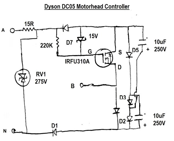
The Motorhead runs off 240V AC from wires embedded in the vacuum cleaner hose. Inside the unit is a 230V DC motor and a PCB which has a dual colour LED among other parts. The circuit was traced out. The motor has never been available as a spare part.
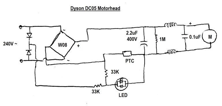
The basic circuit is of a W08 bridge rectifier
feeding the motor. In series with the negative supply of the motor is a
PTC thermistor. If the brush motor is jammed up because of an obstruction,
it draws excessive current which causes the PTC thermistor to heat up and
go high resistance. Thus, the motor is overload protected. The dual colour
LED is normally green when power is applied. Under overload conditions
it changes to red. It's quite an ingenious but simple circuit that does
this. The LED is a two terminal device with the actual LED's inside connected
inversely. Thus, the LED shows green for one polarity, and red for the
other. Under normal conditions, the LED is fed via one of two diodes (depending
on mains polarity) and the 33K resistor connected to the junction of the
diodes. Polarity is such that the LED glows green. The junction of the
PTC and 2.2uF capacitor is negative. The PTC is low resistance, and therefore
the second 33K resistor is effectively connected across the LED. At only
2V across the LED, it has no effect.
Under conditions of overload, 240V DC
appears across the PTC. Now, because the PTC is in the negative return
of the motor circuit, the junction of the PTC and 2.2uF is now positive,
relative to the negative terminal of the bridge rectifier. The LED polarity
is now reversed and it glows red. The second 33K now limits the current.
RFI is reduced by the two chokes and 0.1uF
capacitor. This is actually a 275V AC type. The 2.2uF provides some partial
filtering for the motor's DC. If this capacitor was of higher value, the
motor would actually be fed with 340V DC (peak of the 240V mains supply)
which would be excessive.
For the purposes of testing, the motor
itself runs happily on 12V DC at low speed.
New belt and aluminium pulley fitted.
Some of the live PCB tracks can be seen.
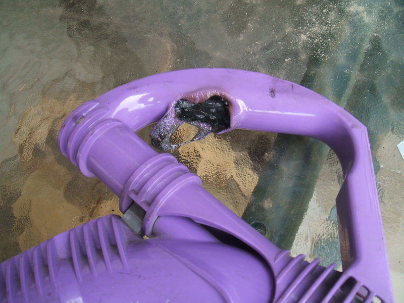
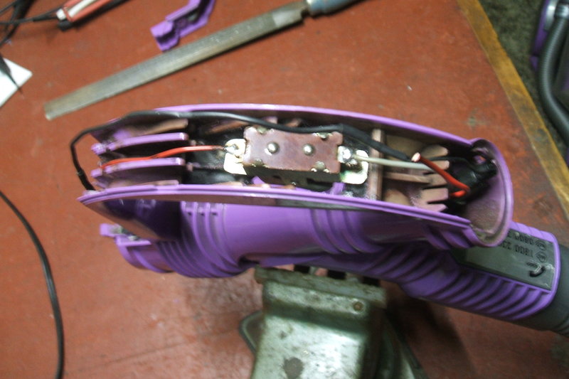
Opening the handle is surprisingly simple with only one Torx screw to be removed.
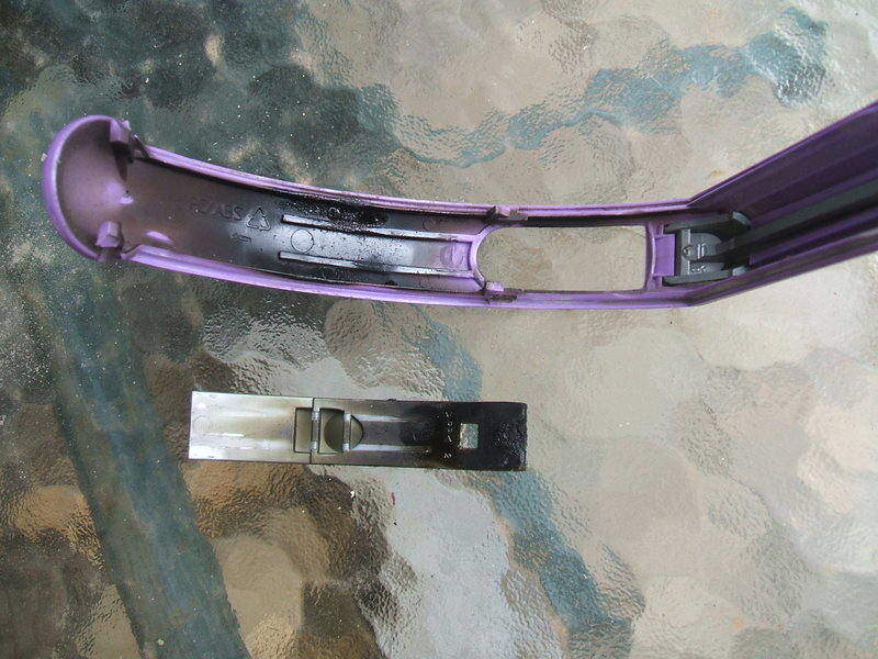
Insides covered in black sticky substance.
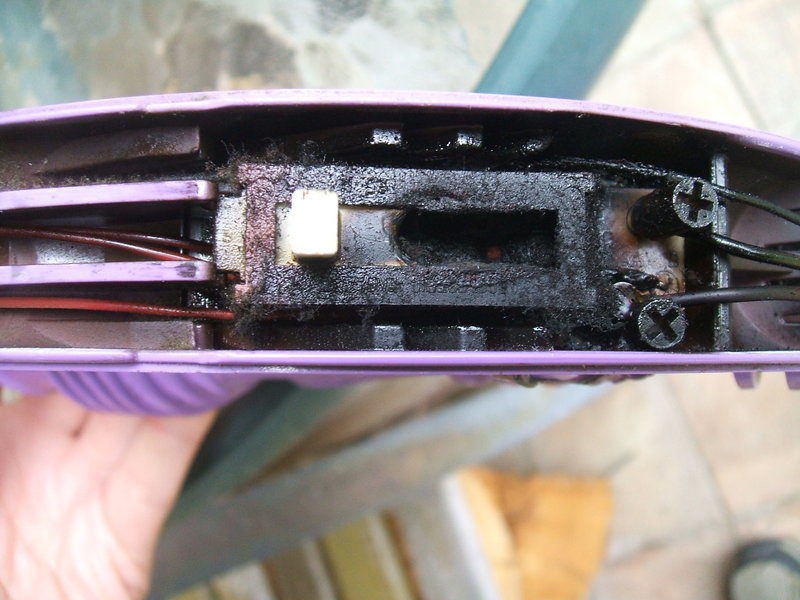
Cause of the burn up. The switch is poor quality.
It had been noted that for a long time
the switch had not provided reliable connection; it being necessary to
move the slider critically to get both suction and the Motorhead to operate.
There is also a PCB in the handle which
controls the Motorhead.
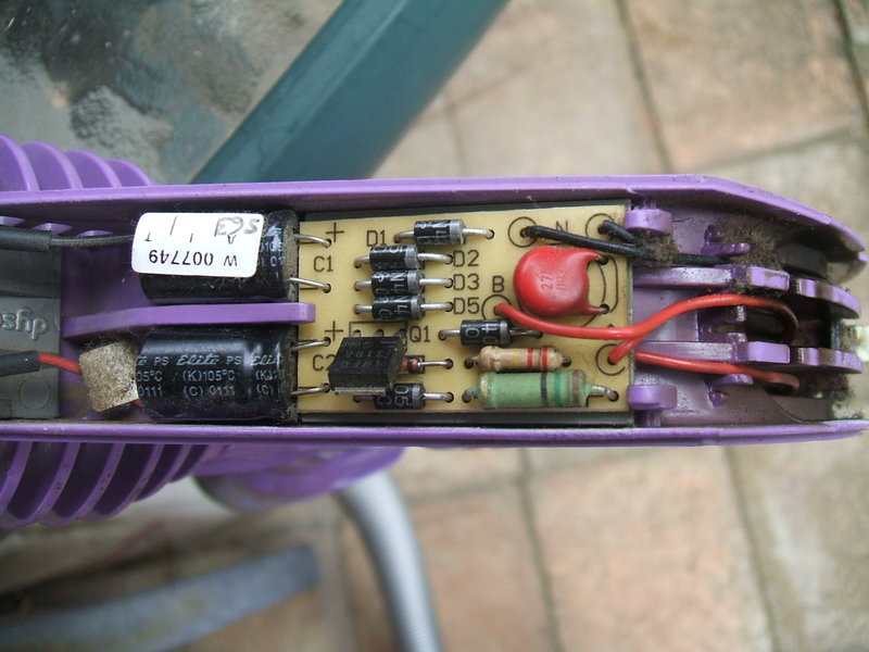
Brush speed controller.
The switch has four positions; Off, suction
only, suction with brush, and brush only. In the brush only position, the
brush motor runs at reduced speed. As such it was assumed this PCB was
used to obtain the reduced speed.
The circuit was traced out.
Three wires are embedded in the hose between
the vacuum cleaner body and the hose handle. The hose is detachable at
the vacuum cleaner body. The wires connect to the switch in the handle.
One wire is the neutral, required for the Motorhead, another is the incoming
live supply from the mains, and the third is the live supply back to the
suction motor.
Two wires leave the handle to feed the
Motorhead. They are embedded in the telescopic wand. The wand is detachable,
and the Motorhead can be connected directly to the handle if required.
N is the common neutral connection,
common to the mains neutral, suction motor neutral, and Motorhead neutral.
The Motorhead is connected to N and B when Zorb is selected.
A
is the mains active (live).
The circuit is unusual and I do not fully
understand it. It is clearly a half wave device, and tests confirm this.
Normally, a simple half wave speed reduced comprises a single diode and
nothing else. It works by chopping off every alternate half of the mains
cycle, with the result being the load is fed with half power.
There is an inline fuse (1A M205) in the
neutral, located in the handle just behind the switch. This protects the
Motorhead and control circuit only.


Normal half wave control provides 170Vrms to the load. To the right
is the waveform fed to the Motorhead when this controller is switched in.
Here, the resultant output is much less
than half power. Judging from the brightness of an incandescent lamp connected
instead of the Motorhead, it looked to be about 70V. Obviously, the
MOSFET is the active component. Given no heatsink, it was clearly operating
as a switch, and not as a variable resistor. Looking at the waveform, it
appears the MOSFET switches on when a certain voltage on the mains sine
wave is reached, and then switches off when the voltage reduces back to
that level.
At this point, it is unclear just how
the circuit switches at the correct time, despite the simplicity of the
circuit. It seems to be load independent because the same waveform was
obtained with a 7W light bulb.
There is a BZXC79C15 zener diode across
the MOSFET gate which prevents the gate seeing negative voltage, and also
ensuring the gate cannot go positive by more than 15V. This is standard
practice with many circuits. The gate is biassed on with the 220K resistor.
As I have never used the "Zorb" function, and never will, the low speed function for the Motorhead brush is not actually required. This means the controller PCB can be removed, and all that is required is a simple single pole switch in the handle for the full 240V AC to the Motorhead. One room in my house has particularly long carpet which jams up the Motorhead. For this reason, it's necessary to be able to turn off the brush motor.
New Switches.
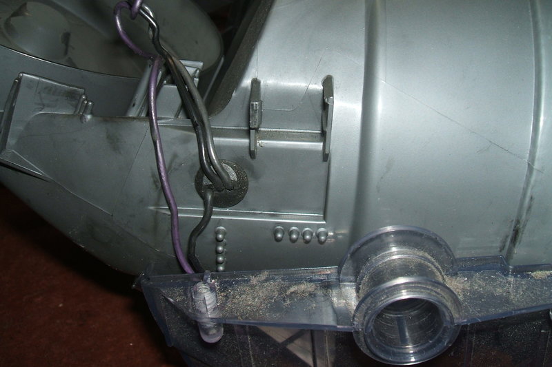
Motor wires emerge here. The black wires are connected together.
Purple is mains live to the handle switch, black is neutral, and grey is
switched live to motor. Note unused switch mounting.
First thing to do was install the main
switch on the motor housing. Generic switches are readily available on
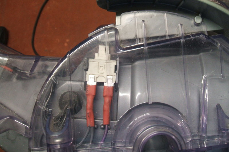
ebay and one was purchased. Connection is via 4.8mm quick connect lugs.
The switch fitted straight into the moulded clips, and the actuator worked
perfectly.
At this point, the vacuum cleaner was
now operative as the base model.
Mains switch installed. Machine is now functional as the base model
DC05.
Next was to deal with the handle switch
for the brush motor. I filed away the burnt parts of the handle that
were protruding so as to give a flat surface again. Looking through my
collection of switches, I found one that was actually long enough to bridge
the elongated hole.
As the speed controller was no longer
going to be used, the PCB was removed. Thus, the switch only needed to
be a simple SPST type. It was secured to the handle housing with miniature
nuts and bolts.
It was found the inline fuse had blown,
so this also had to be replaced.
Switch mounted in handle over burnt out hole.
The original switch slider was replaced to fill the hole in the top of the handle. It relies on the plastic moulding to keep it in position; the switch is not needed.
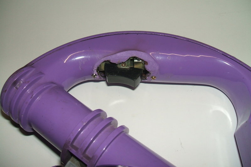
Not very pretty, the new Motorhead switch is functional.
All worked perfectly, and the DC05 Motorhead is now functional again. In fact, I would say it will be more reliable without that original slide switch - a poor choice for a high power inductive load.
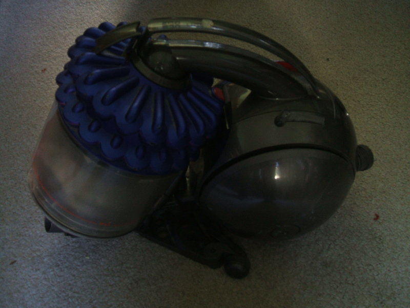
This DC-54 came my way, and what a disappointment!
It had been 'got at' with a couple of the Torx screws missing underneath
where the steering mechanism attaches. The machine didn't power up at all,
and before getting involved, experience tells that it's best to have a
quick look at the motor before getting involved too far.
What a daft design! Dyson would have you
believe their cyclone bin is perfect and is the reason that their vacuum
cleaners 'never lose suction'. The reality is that it isn't, and the DC-54
is a good demonstration of that. You see, not everything is caught in the
bin. In the DC-05 and other models, there's a filter between the bin and
the motor. In the DC-54, the air from the bin passes straight into the
turbine and out through the back of the motor. Then there's a filter -
after
the
dirt has been sucked through the motor. This filter is not a user replaceable
or washable part. It is interesting to note a label visible when the bin
is removed to say that the machine should not be used with plaster, ashes,
or rubble. How limiting is that!?
In my example, there was human hair right
through the turbine, jamming it up, and it had passed through the motor
into the exhaust filter. The motor itself was inoperative with the brushes
worn to the point where no contact was made. The brush material was dispersed
throughout the filter. I noted the nut securing the turbine was missing
and the washer was found in the filter. Perhaps the nut is stuck in a turbine
blade?
Anyway, all that didn't give me much enthusiasm
to repair it. Dirt being sucked through a motor, all over the bearings
and commutator and past the windings. Not very clever.