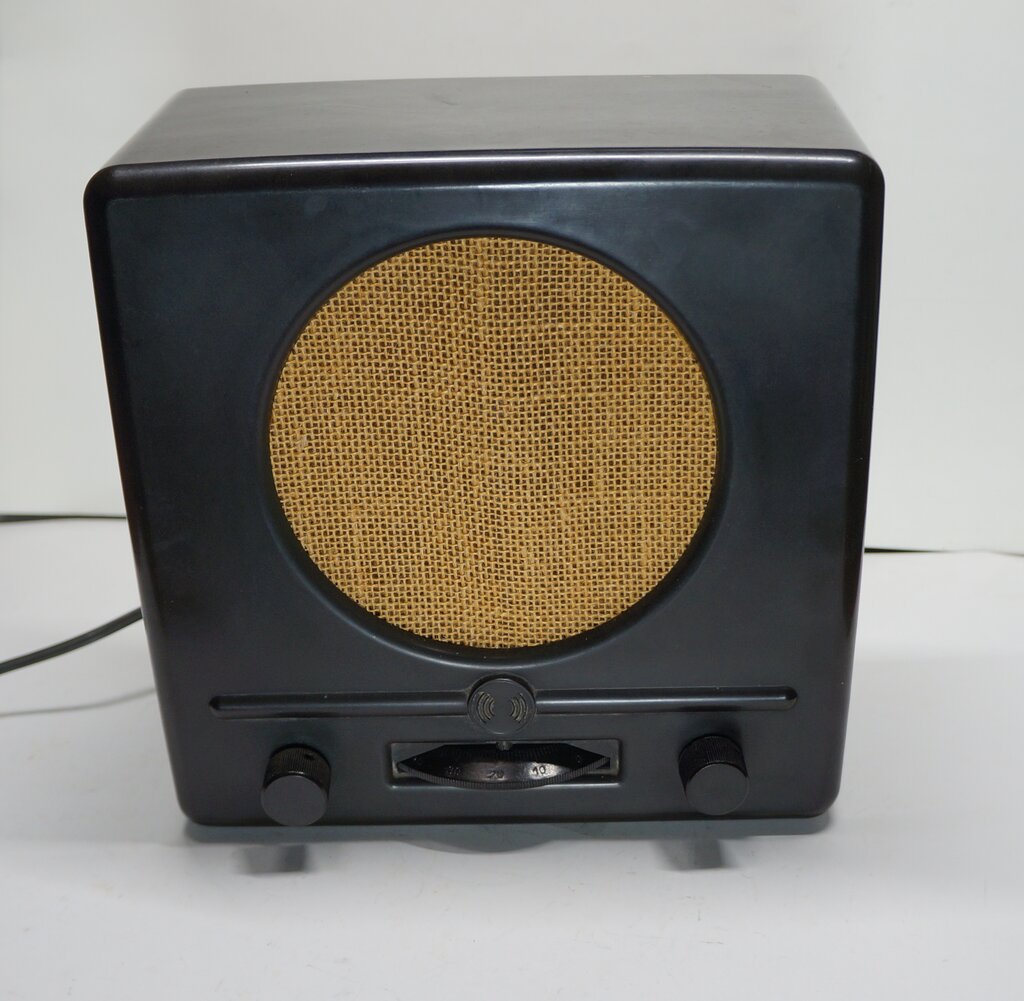
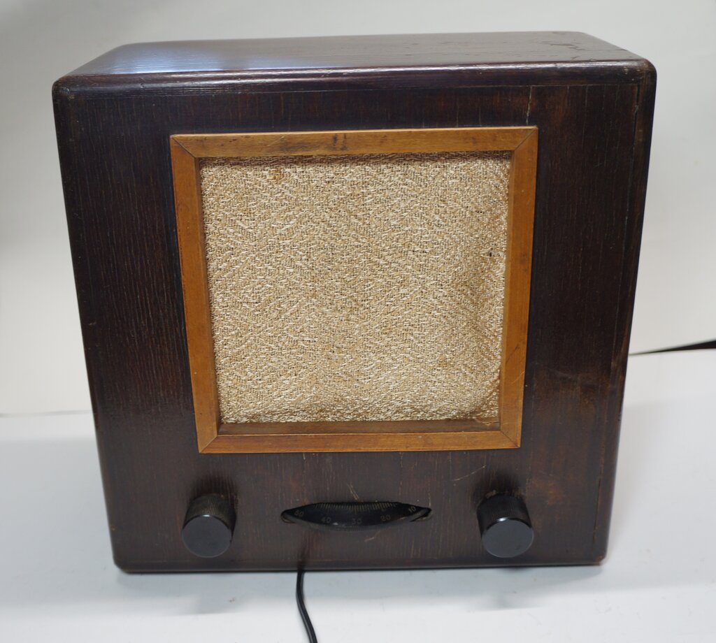
Note the absence of the Swastika - this set is post war.
Note the absence of the Swastika - this set is post war.
The DKE 1938 (or DKE 38) belongs to the Volksempfänger (peoples' receiver) series of German receivers. These were built to a low price, with the intention of all German homes being equipped with a radio receiver, and thus able to receive Nazi propaganda. They were manufactured by 28 existing manufacturers, all to the same design.
The first in the series was the VE301 from 1933. This model number is derived from Volks Empfänger 30th 1 (January) - the day the Nazi party came to power in 1933. It used a three valve regenerative circuit for operation on AC mains. Battery and DC mains versions were subsequently produced. Reception covers the MW and LW bands.
In 1938 came the DKE 1938. (Deutschen Klein Empfänger - German small receiver). This was a further simplification, being a two valve AC/DC design. Two new valves were designed by Telefunken specifically for this set; the VCL11 and VY2. A three valve version was also made for battery operation. This set continued to be produced post war, along with a few other designs, although of course without the Nazi symbols.
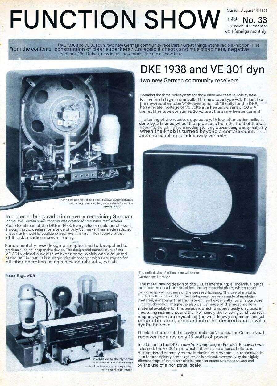
English translation from "Funkschau", issue 33, 1938.
I had known of the Peoples' Receivers (or 'Nazi Radios', as I call them) for many years, since there had been articles in magazines, and they had come up for sale at HRSA auctions. The fact that they were a mass produced minimalist regenerative receiver is what always interested me. And of course, my liking for live chassis series heater designs.
Then, in July 2025, a fellow HRSA member
very kindly offered me a DKE 1938. I was delighted to accept it, since
I had always wanted to know how well these sets really worked. My collecting
also tends to gravitate to the more unusual type of design. It has often
been claimed that these sets were deliberately designed to be insensitive,
so as to prevent reception from neighbouring (Allied) countries. I've always
been sceptical of this for two reasons; a regenerative circuit is by its
nature very sensitive, and what if the listener was situated adjacent to
a border, with an Allied transmitter nearby?
The DKE 1938.
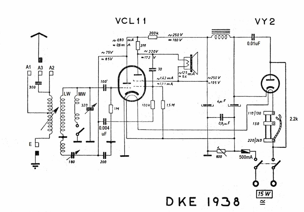
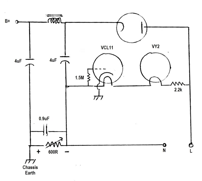
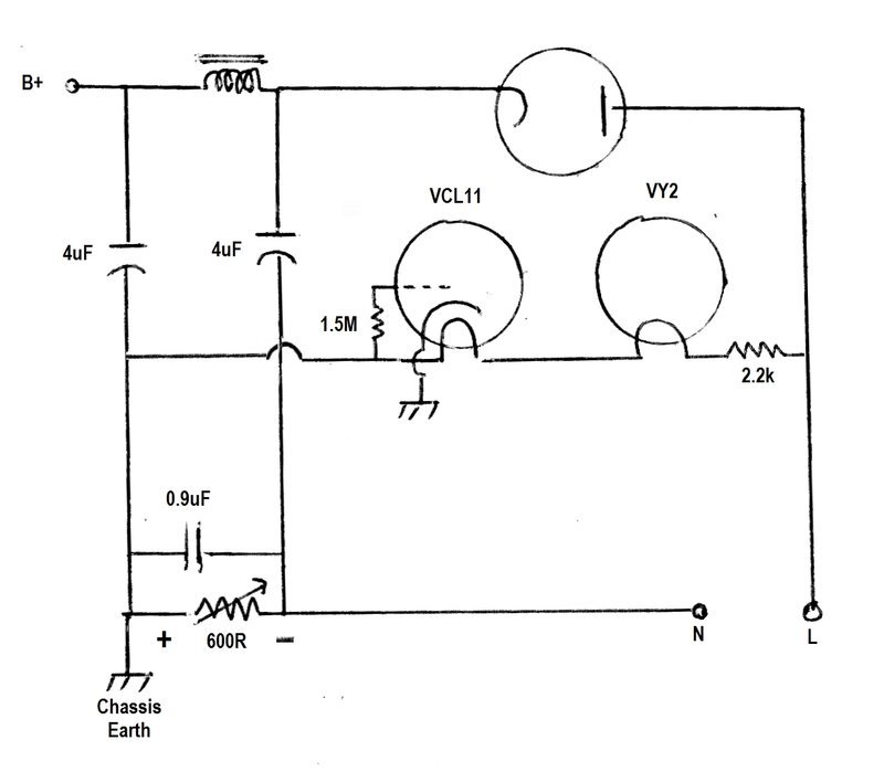
Circuit of the DKE 1938. Voltages and currents marked "~" are for
220V AC mains, and "=" for 220V DC. For longevity of the VY2, a 330 ohm
1W resistor should be connected in series with its plate or cathode.
Detector.
The VCL11 triode (C section) functions
as a regenerative detector in a very typical circuit. The aerial coil design
is quite interesting, however. The primary is mounted on a swinging mechanism
so that the degree of coupling is user adjustable. This is the function
of the knob on the left hand side. The intention is for the volume of the
set to be controlled by varying the coupling. This saves the cost of a
potentiometer. Additionally, in areas of high signal strength with multiple
stations, reducing the coupling improves selectivity. To further help with
selectivity, there are three aerial input sockets. Two of these select
either the full primary winding (A2), or a tapping (A1). The third (A3)
connects the aerial to the full primary via a 300pF condenser.
Depending on the length of aerial used,
and the reception conditions, the choice of input is made for best volume
and selectivity.
There is an iron dust core in the primary
coil. The bottom of the aerial coil connects to the external earth connection
in the usual way. Despite being a live chassis design, no isolating condensers
are required, since the primary coil is itself isolated from the set circuitry.
Because of this, the set requires an external earth to function.
The aerial coil secondary is tuned by the 320pF variable condenser. Note that there are two secondary coils; one for each band. The larger coil tunes the LW band. When MW is required, the additional coil is connected in parallel, which reduces the overall inductance, thus increasing the resonant frequency.
Band switching is done by a cam switch on the tuning condenser itself. The tuning condenser physically rotates over 360 degrees, and the dial is divided in half with two 0-100 scales. One scale is white (MW) and the other is red (LW). For half the rotation the cam switch is closed. The end result is that you are tuning over the same capacitance range for both scales, but for the white one the extra winding is in circuit. It makes for simple operation, since one just tunes in the required LW or MW station, without manually switching bands.
The detector is a typical grid leak circuit with 100pF condenser and 1M resistor. Detection takes place between the grid and cathode, since these function as a diode in this configuration. The 100pF and 1M perform as the diode load, as far as detection is concerned. The grid thus develops the demodulated audio component, which is then amplified by the triode circuit. The amplified audio signal appears at the plate, across the 200k load resistor. The RF component is largely bypassed to earth via the 200pF condenser. RF entering the following audio stage is undesirable since it can lead to instability.
Regeneration.
Since the RF component of the input signal
feeds the grid, it too is amplified. By feeding some of this back into
the tuned circuit, so that the feedback is positive, further amplification
is possible. By feeding amplified RF back into the input, the input signal
is effectively much stronger, which then of course means a stronger audio
signal. Additionally, selectivity is vastly improved since the feedback
makes up for losses in the tuned circuit.
If the amount of RF feedback is excessive,
the circuit will oscillate and reception will be unintelligible. If the
feedback is minimal, so too is the regenerated signal. Therefore, the optimum
amount of feedback is as high as possible without the circuit starting
to oscillate. The feedback is adjustable by the 180pF variable condenser.
This acts as a variable impedance to the amount of RF flowing to the feedback
winding.
While most of the RF signal at the triode
plate is bypassed, there is still enough to provide sufficient feedback.
Because of such factors as aerial loading,
supply voltage variations, and the amount of feedback depending on what
frequency the set is tuned to, the regeneration control has to be user
adjustable. This is the knob on the right hand side. Since the amount of
feedback controls the sensitivity, one could envisage this control being
used to adjust the volume. It will indeed do this, but selectivity will
worsen as the volume is reduced. At the minimum setting, selectivity will
be not much better than a crystal set.
The proper way to operate a regenerative
detector is with the feedback as high as possible without oscillation,
and then controlling the volume either by adjusting the RF input (as done
here), or by a volume control in the following audio stage.
Audio Output.
The output stage uses the beam tetrode
(L section) of the VCL11. The audio from the detector feeds the tetrode
grid via the 0.004uF isolating condenser and 100k 'grid stopper' resistor.
The latter acts with the grid to cathode capacitance to form a low pass
filter. It improves stability of the tetrode, since any feedback which
might cause instability is likely to be at higher frequencies. In this
circuit, it also removes additional RF signal still present at the triode
plate.
The screen grid and plate are connected
to the B+ and speaker respectively, in the usual way. Speaker impedance
is 17k. Somewhat surprisingly for an inexpensive simple receiver, there
is negative feedback. This is provided by the 2M resistor. It is connected
in a shunt feedback circuit between the two plates. Effectively, this is
the same (in terms of the audio component) as connecting it between the
tetrode plate and tetrode grid. Since the plate is 180 degrees out of phase
with the grid, the feedback is negative. The amount of feedback is roughly
the ratio between the 2M resistor, and the 200k in parallel with the resistance
of the triode. Literature concerning the design implies that negative feedback
is more for mains hum reduction than improving sound quality.
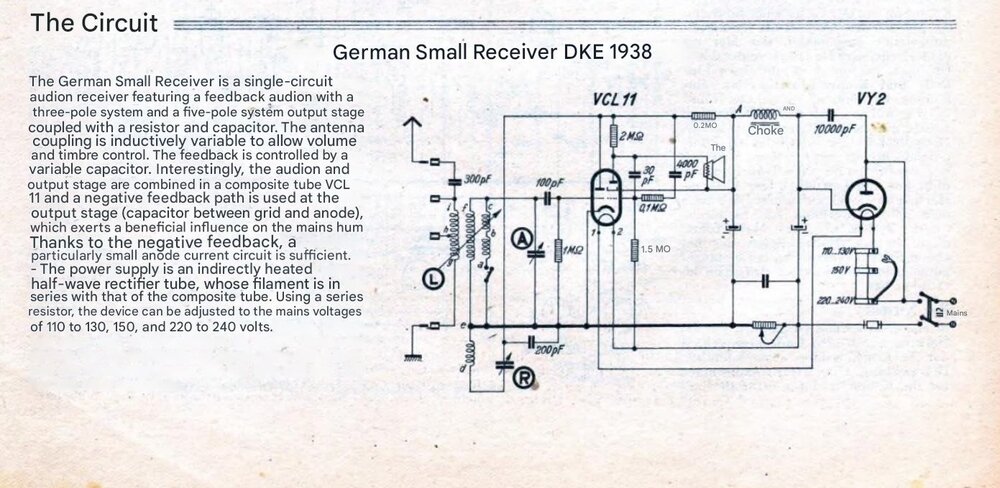
English translation from "Funkschau", issue 35, 1938. Note the reference
to mains hum and negative feedback.
By connecting the 2M resistor between plates,
it makes use of the existing 0.004uF isolating condenser, saving another
component. There is one additional negative feedback path, which is via
the 30pF condenser. It is connected directly between the tetrode plate
and grid. As can be imagined, with such a low value, its effect will only
be for the higher frequencies. Again, it contributes to stability, and
reduces the amount of RF present at the tetrode plate. This is important,
since the speaker wires could otherwise radiate RF back into the nearby
tuned circuit.
Note the VCL11 has a common cathode. This
is earthed for correct operation of the grid leak detector which operates
without bias. The tetrode receives its grid bias via the 1.5M resistor,
which is supplied from a back bias circuit in the power supply.
Power Supply.
A conventional AC/DC series heater type
power supply is used. The heater current is the unusual value of 50mA (hence
the "V" designation). The rectifier is a VY2, with a 30V heater, and added
to the 90V required by the VCL11, the total heater voltage is 120V.
The set is designed to operate at 110-130V,
150V, or 220- 240V. The valve heaters will be slightly under run on 110V,
and slightly over run on 240V, but this is within 10% tolerance. The heater
dropper is tapped at 600 ohms for operation on 150V, and an additional
1.6k is added for 220-240V. No adjustment is provided for the B+ voltage
with different mains voltage inputs. The set has been designed for 220V
mains as the default, and presumably one just accepts reduced performance
with the low B+, when operating from 110V.
The mains is rectified by the VY2, which feeds a conventional filter circuit consisting of a choke and two 4uF electrolytic condensers. Across the rectifier is a 0.01uF capacitor which removes modulation hum. This is often necessary with live chassis circuits, because the direct connection to the mains means that RF picked up on the mains supply is more likely to find its way into the set. Rather disturbingly, there is no surge limiter for the rectifier, with the mains fed straight into the VY2 plate, and the cathode straight into the first filter capacitor. The problem is the high peak charging current is detrimental to the cathode.
A 500mA fuse provides short circuit protection should some internal part of the set come into contact with an earthed object. It's placed in series with the earthy side of the power supply, since this is directly connected to one side of the mains. The short circuit current on the other side of the mains is limited by the heater dropper and internal resistance of the VY2. The 500mA fuse is inadequate to protect against a B+ short, and the rectifier will fail instead. A double pole switch on the back of the set switches the mains supply.
While the grub screws for the knobs are accessible, there is no shock hazard because the control shafts are isolated.
The Preset Resistor.
In the negative supply is a 600 ohm adjustable
resistor, bypassed with the unusual condenser value of 0.9uF. This is the
back bias supply which provides the VCL11 tetrode with its negative bias.
There is some contention about the designation of this control. In the
DKE 1938 instructions, it is designated as "Entbrummer", which means 'hum
eliminator'. The instructions say to adjust it if the set hums too loudly,
which is only necessary after changing a valve or supply voltage.
The indisputable fact is that this 600
ohm resistor is a back bias circuit, and adjusting it varies the bias to
the VCL11 tetrode. How this is supposed to reduce the hum is questionable,
and furthermore, misadjustment will result in no bias and excessive current
flow.
Providing this as a user adjustable preset
is rather unwise, since a non technical person would have no idea if the
VCL11 is destined for a short life, once they've randomly twiddled it with
a screwdriver. However, the part about adjusting it after changing the
valve or mains voltage does make sense, and is what I would expect. Reducing
the bias would be applicable with the lower B+ on 110V. Sensibly, later
sets have a 300 ohm fixed resistor instead of the adjustable control. One
has to wonder how many VCL11's were, and still are being damaged by incorrect
adjustment.
It is worth noting that the earlier AC only set, the VE301 does have a hum control. This is the genuine thing; being a centre tapped pot across the heater supply for the output valve. This is necessary to balance the heater supply, since the output valve is directly heated. My strong suspicion is that a non technical draught person has used the same instructions when compiling those for the DKE 1938.
Minimising the Metal Content.
There is very little metal in the design.
The most obvious and expensive part to eliminate is the power transformer,
using a dropper resistor instead. Perhaps one of the most attention getting
aspects, is the construction of the speaker. It's made of compressed fibre
and uses a high impedance driver reminiscent of a 1920's cone speaker.
An aluminium/nickel (Alnico) permanent magnet is used. Using a high impedance
driver eliminates all the copper and iron that a speaker transformer would
require. The avoidance of metal in construction is also emphasised with
the chassis itself, being of something akin to phenolic/paxolin/SRBP (synthetic
resin bonded paper). This material is also used for the variable condensers,
which are of a plastic dielectric type. The cabinet itself is bakelite
with a fibre board back.
Surprisingly, there is a filter choke,
albeit a small one. Much later versions used a filter resistor instead.
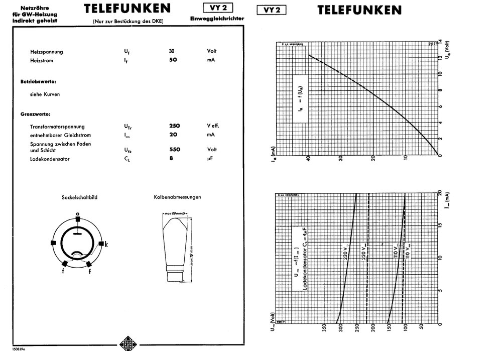
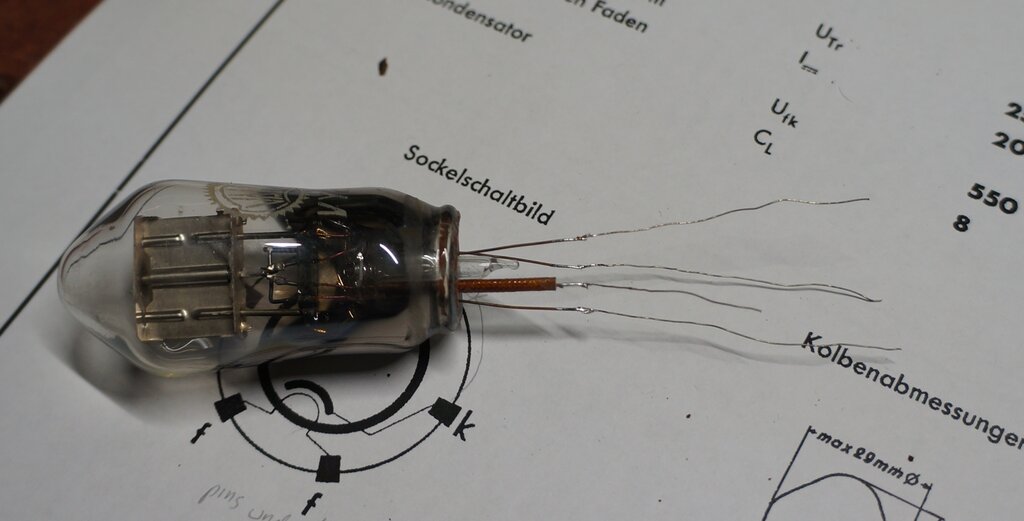
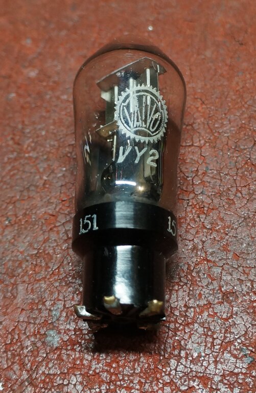
Data for the VY2. This is a small half wave rectifier with only 20mA
current rating. Base type is P5, which was used with very few valves.
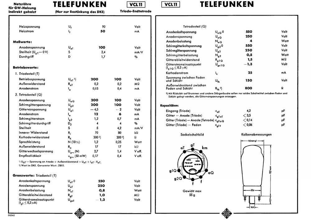
The VCL11 uses a slightly more common G8A base. The valve is a triode
with beam tetrode, sharing a common cathode. Gain of the beam tetrode is
slightly higher than a 6V6, but power output is considerably lower.
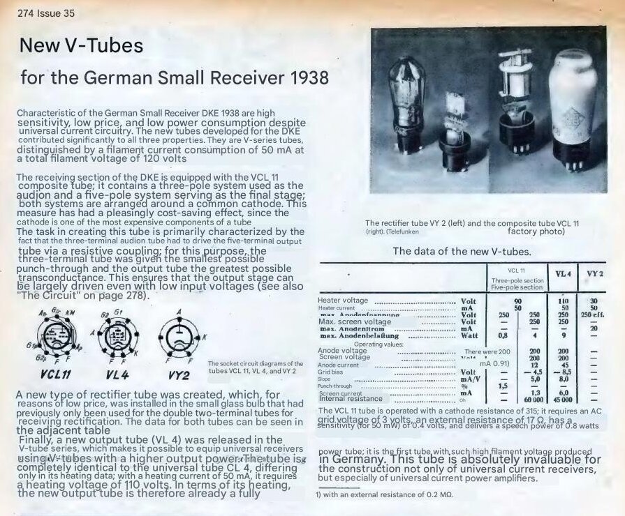
English translation from "Funkschau", issue 35, 1938.
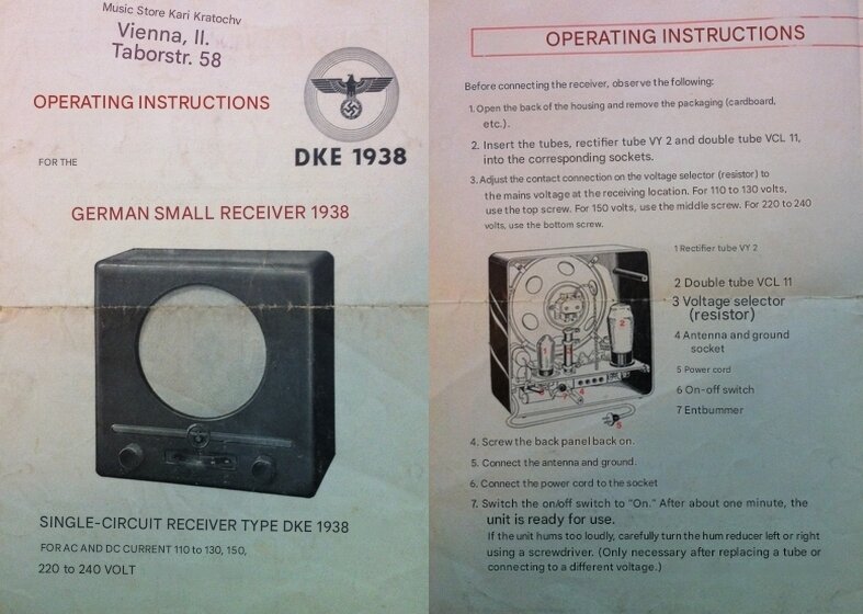
Instructions translated to English.
The instructions appear a bit vague in parts, and it would appear that the user was assumed to be familiar with radio, to get the best out of it. In step 5, it is assumed the user knows what a ground connection is, although the back cover of the set does show a symbol for a connection to a water pipe. Step 7 describes adjusting the preset resistor. As mentioned previously, the user would have no idea if the output valve is correctly biassed. In step 9, the procedure for "correctly selecting the antenna socket" is glossed over. Step 10 describes in a vague way how to adjust the regeneration control. It does say not to let it oscillate, but nothing beyond that. We do get something meaningful with the aerial coupling, or "volume" control, and how it can improve selectivity. Perhaps one should take into consideration at the time, that people in general had a better understanding of radio, and a lot of it would be common sense. I doubt the modern generation would be able to operate the set with these instructions.
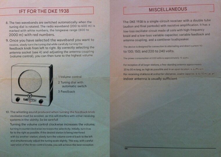
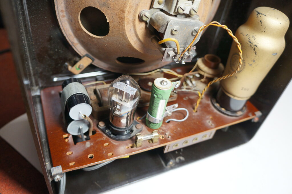
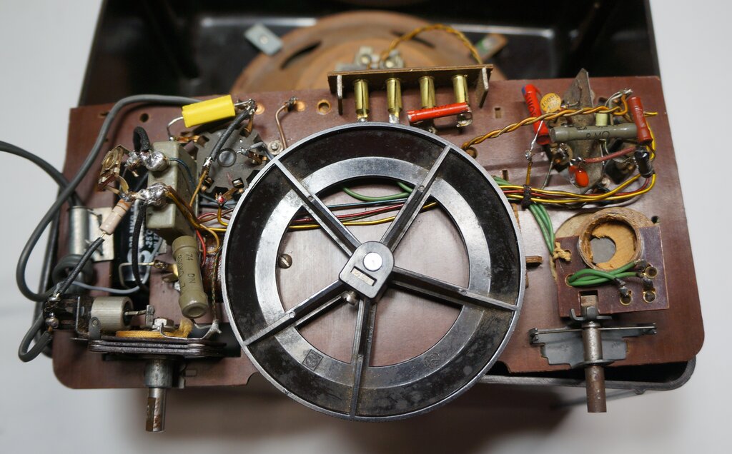
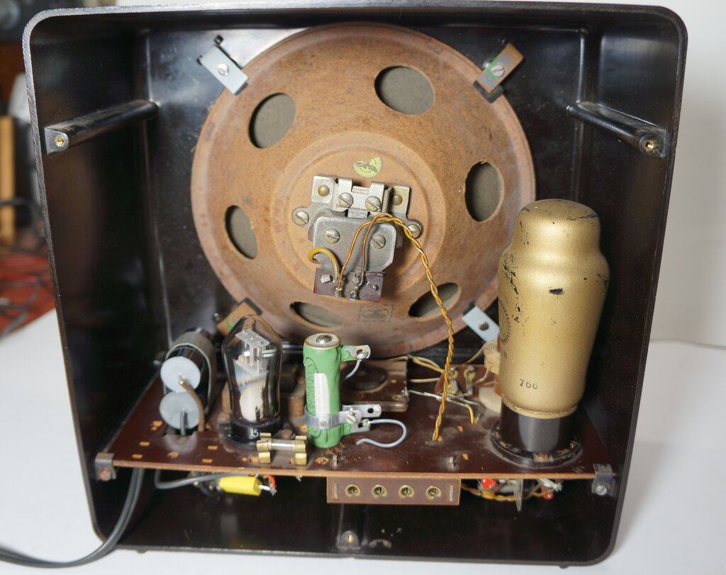
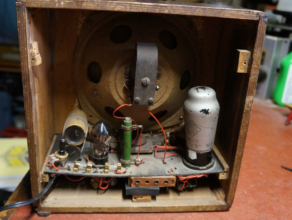
Under the chassis. Note the swinging aerial coil at the right.
The bias control was obviously not original,
having been replaced by a modern 1k trimpot. The first filter capacitor
was a 4.7uF 400V electrolytic removed from other equipment, with one of
its connections in mid air to a length of the above mentioned brown wire.
Above the chassis was the 2nd filter capacitor, this time a 16uF 350V Philips
from the 1950's. Across the rectifier was a silicon diode type IN1490.
Instead of the 0.01uF capacitor was a combined 0.033uF + 120 ohm snubber
network. Such devices are intended to be connected across switches to reduce
sparking. The capacitor absorbs the voltage which otherwise causes the
spark, and the resistor limits the discharge current when the capacitor
is charged and the switch is closed. The intentions were good, but the
120 ohm might reduce the efficiency of the capacitor. The other component
replaced was the 100pF grid leak.
There had been an extraneous component
added; a 2500pF condenser from the earth terminal to the side of the mains
connected to the fuseholder. It would appear the previous restorer didn't
want the inconvenience of having to make an earth connection, instead using
the mains for this purpose. No wonder I was getting a slight spark when
connecting the aerial. Given that such a connection would be liable to
contribute to hum, and that the condenser was inadequately rated at 500V
DC, it had to go. For 240V AC, the peak is 340V, which means the peak to
peak, which is what the condenser is exposed to, is 680V.
A better way to achieve an earth connection
using the mains, would be to fit the set with a three core cable, with
the earth wire connected to the earth terminal.
The bypass condenser across the trimpot
looked period correct, but although it was branded Bosch, the writing was
English. It is hard to be sure, but I suspect it was not original. It is
1uF. The grid coupling condenser was found to be 2500pF, rather than the
listed 4000pF, but looked original.
The only resistor slightly out of tolerance
was the 200k, which measured 240k. In view of it being non critical, I
left it in situ.
Above the chassis, the most obvious replacement was the dropper resistor. This had been replaced with a 200 ohm and 2000 ohm 20W resistor in series. Also, the steel clamp for the filter condensers had been squeezed together to secure the single 16uF present.
The aerial coil had me confused for a while because it rotated normally until I took the chassis out. Thereafter, it could not be swung into the fully coupled position. It turned out that the iron core slug had slipped out of position, jamming up the mechanism. With the chassis horizontal, it naturally fell into its correct position. The iron core is secured in a wooden dowel which sits in the coil former. A small amount of glue fixed that problem.
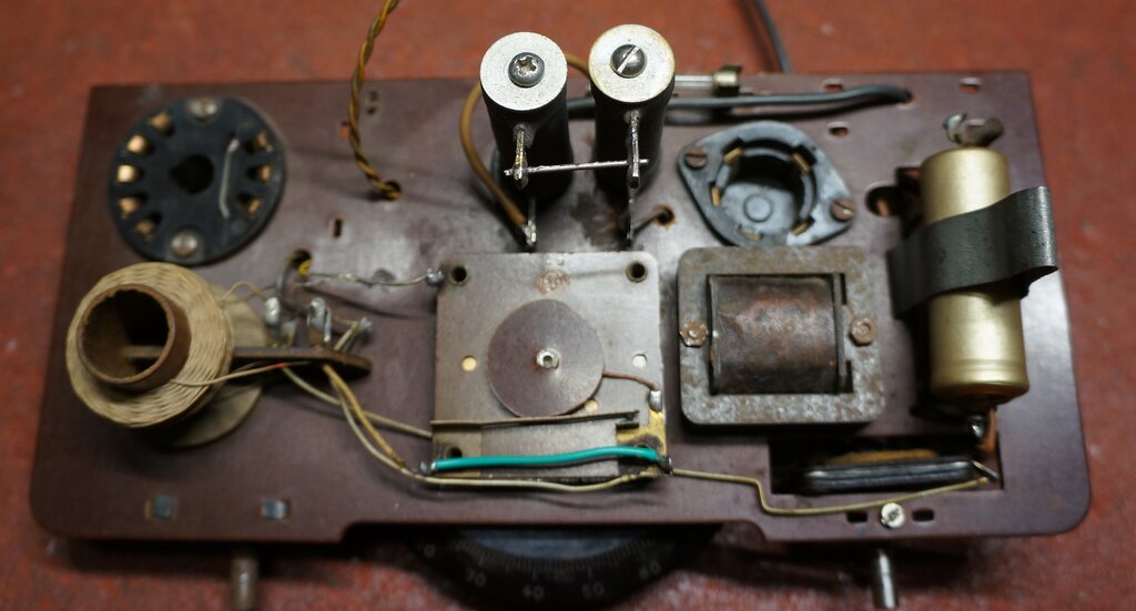
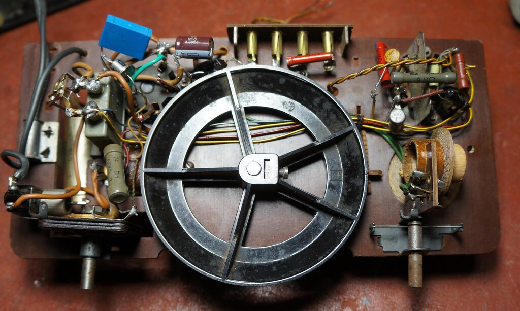
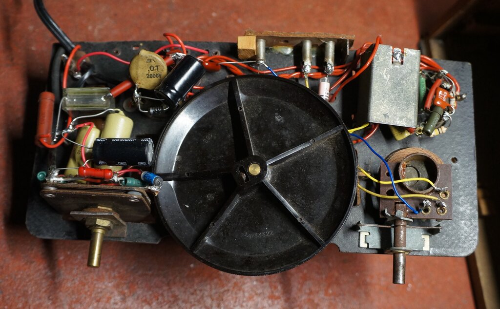
Above chassis with valves removed. Note the band switch has been
bridged out with the green wire.
Also noticed was the MW switch had been bridged out. I did test the radio as it was, and got results of sorts. There was some hum, and the output power and sensitivity wasn't as good as I thought it should be.
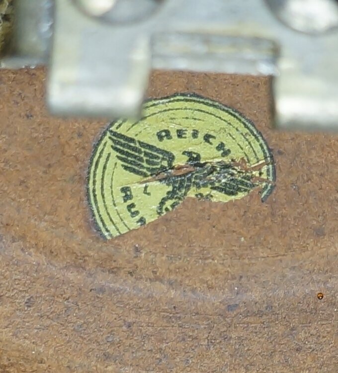
Nazi Symbols.
This particular set was manufactured post
war, and thus did not have the Swastika on the front panel. Instead, there
is a rather bland arrangement of arcs. However, inside the set several
of the parts did include eagle and Swastika symbols. This suggests that
wartime stock was still being used up.

Sticker hiding the symbol on the VCL11.
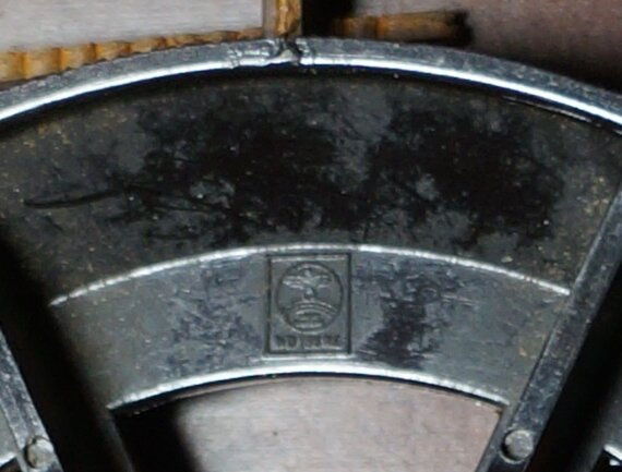
Tuning dial.
Speaker frame.

Tuning condenser.
Dropper Resistor.
I calculated that for 240V, the dropper
resistor should really be 240 -120 / 0.05 = 2400 ohms. Given the rarity
of the valves, it's best to do the right thing by them. Also, two resistors
looked out of place, especially as the 200 ohm one was grossly over rated,
dissipating only half a watt. Not that it matters of course from an electrical
point of view, but it really is overkill. And besides, a proper single
adjustable resistor would be more original. I found Rockby had 2500 ohm
20W adjustable resistors, so ordered two. Just as well as I did, because
one of those supplied was a fixed resistor instead. The actual power dissipation
in the dropper is only 6W, but 20W is the lowest conveniently available.
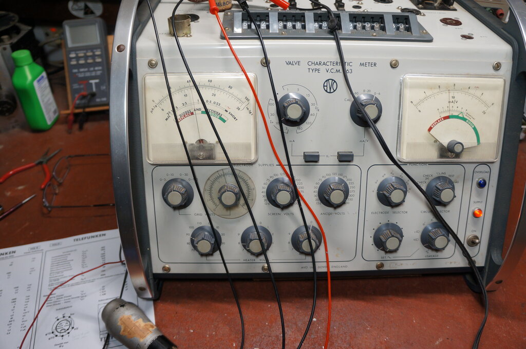
Given the diode bypass, I was sufficiently suspicious of the VY2. I was able to test it on the AVO VCM-163 and found it to be virtually open circuit. It could barely pass 50uA!
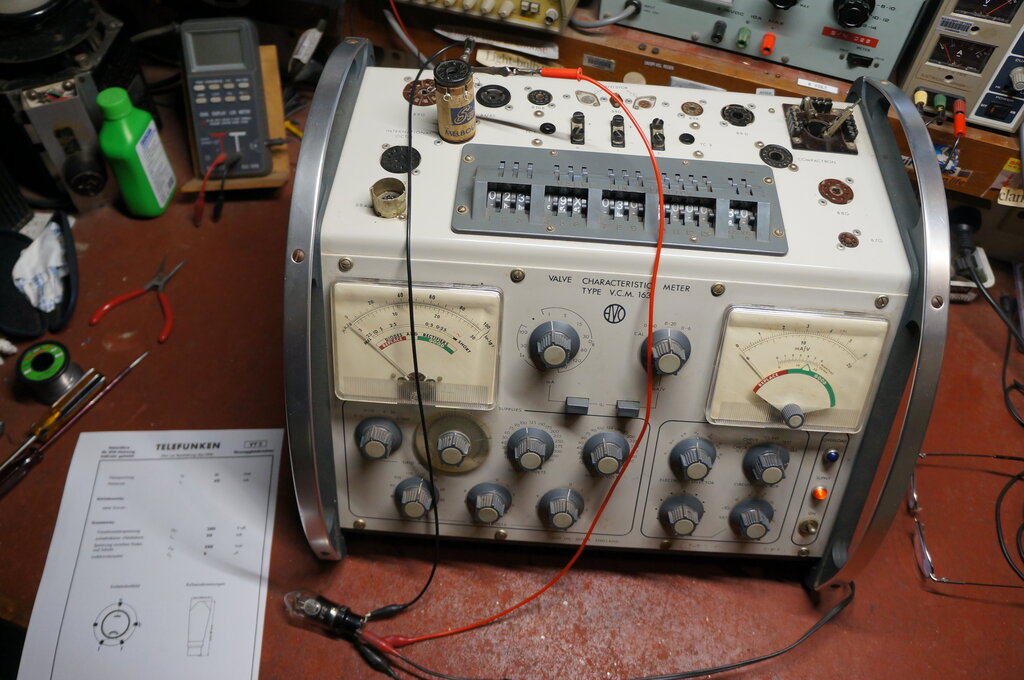
Testing the VY2.
Rebuilding the VY2.
No wonder the silicon diode had been installed.
What to do? An elegant way out of the problem would be to install a diode
inside the base, so that for all purposes the valve looked and functioned
normally. There's plenty of room for the diode, and as the base was slightly
loose, it didn't take much effort to remove it. Care had to be taken to
remove all the solder from the pins, and an electric pump type solder sucker
was used for this. Fortunately, there's only four wires.
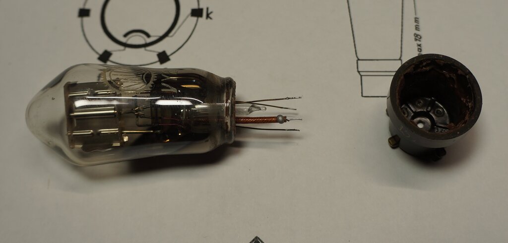
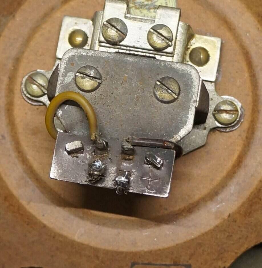
Base removed from VY2.
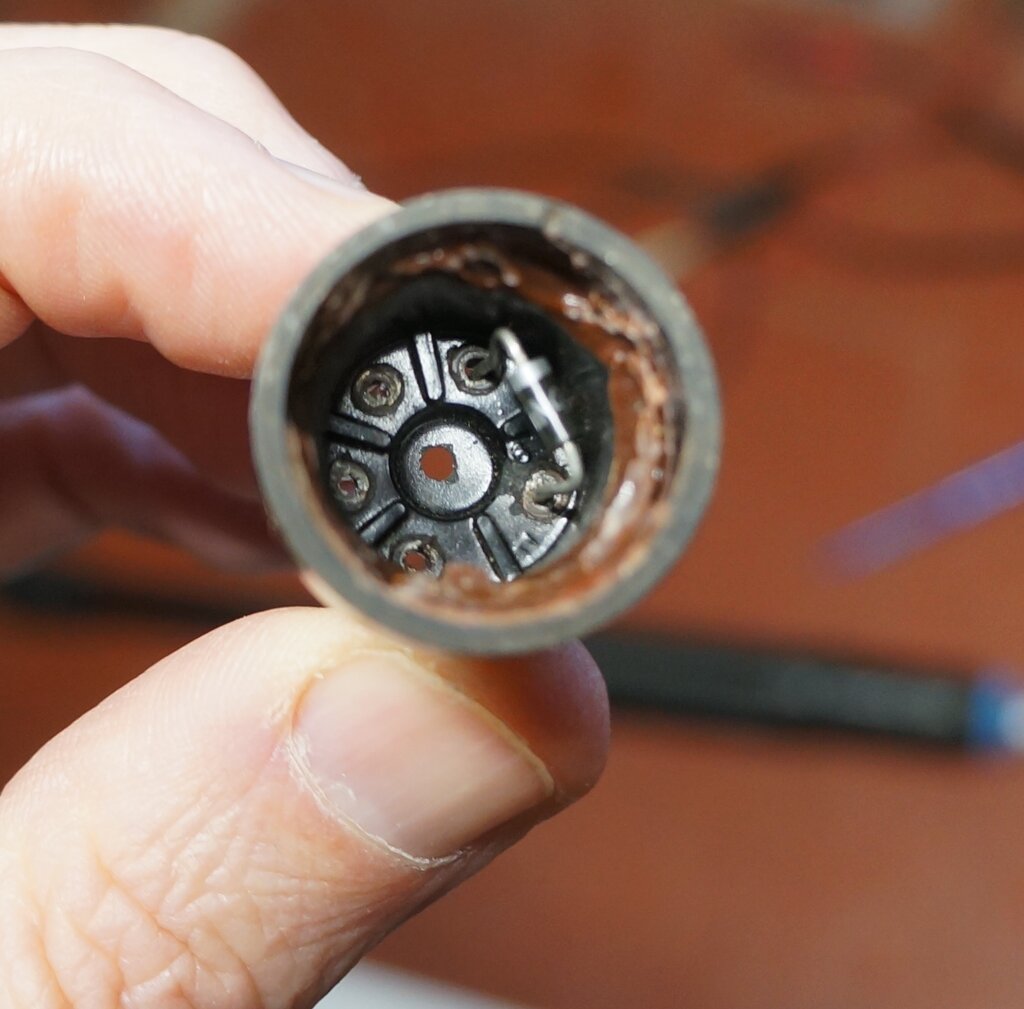
1N4007 diode installed.
Strands of wire soldered on to facilitate threading through the
base pins.
Valve reassembled. No one would ever know!
I used black silastic to secure the base
back onto the glass. Not only can the excess be easily removed after it
has dried, but if necessary the base can be removed again. I am always
loathe to glue bases on with epoxy, etc.
The VY2 is only used for its heater to
drop the correct voltage. It tests and functions like a 'proper' VY2, except
for a lower voltage drop, which brings up another subject.
Surge Limiter.
It is bad practice to operate rectifiers
straight from the mains into a filter condenser. The capacitor appears
initially as a short circuit until it charges. Then towards the top of
each cycle, the rectifier has to supply not only the current of the set,
but also the current to charge the condenser. Valve data usually lists
the minimum series resistance, which in most instances is already part
of the transformer secondary winding. For direct mains operation, a separate
resistor is required, since the mains supply has virtually no impedance.
Unfortunately, the DKE has no surge limiter
resistance. This would explain why so few VY2's have survived. I installed
a 330 ohm 1W resistor, should a functional VY2 ever be installed, but also
it compensates for the lower voltage drop when the silicon diode is used.
The snubber network across the rectifier
was replaced with a 0.01uF 1kV capacitor. Such a high voltage rating is
required because when the first filter condenser is charged to +250V, and
the mains is at the peak of the negative cycle (-340V), the voltage across
the rectifier will be 590V.
Filter Condensers.
The 16uF filter had to go. Not only it
was grossly different to the 'correct' value, but I wanted the set to function
electrically as original, which included seeing what the hum was like with
4uF. Modern electrolytics are much smaller than the originals, and the
large metal strap above the chassis really needed something to fill it.
If it was some common Australian mantel radio I wouldn't have bothered,
but for a historical set like this, I felt some effort should be made to
keep the aesthetics.
To this end, I found modern 400V polypropylene
capacitors to be a pretty good substitute. They're available in 4uF and
are sold for speaker crossover networks. I bought a pair on eBay. Dimensions
are 20mm diameter by 35mm long. That's smaller than the original, but they
look the part. It was necessary to shorten the strap slightly to ensure
a good fit. A 5/8" socket spanner makes a good mandrel to bend the curve
into the strap.
4uF condensers and dropper resistor look the part, even though they're
new.
Mistake Found - No Bias.
While installing the new dropper, and
tidying up the wiring I discovered an interesting mistake. The heaters
had been powered through the back bias circuit! The result of this incorrect
connection was also that the VCL11 tetrode was operating with no bias.
Given that it's unlikely the radio had
been used much since its 'restoration', I felt the VCL11 had probably not
been too badly damaged. It would explain the poor performance when I first
tried the set.
The parallel combination of the 1uF and
1k trimpot (set to 264 ohms) had been carrying the 50mA of heater current
without complaint. I measured 11V AC across the back bias circuit. Had
the bias actually been connected to the VCL11, the hum would have been
intolerable.
It's probably because of this that the
mistake went unnoticed, and the set was just assumed to be 'another poor
performing DKE'.
Original basic circuit of power supply.
To see what went wrong, examine the above
circuit, which is as the set was originally built. For physical wiring
convenience, the 1.5M grid resistor earth connection shares the same wire
as the earthy side of the VCL11 heater. It is connected at the valve socket
between the grid and earthy heater pins.
Because of the current flow through the
back bias resistor, a voltage is developed with the polarity shown. The
set's earth reference, and VCL11 cathode, is therefore positive with respect
to the negative terminal of the first filter condenser. It follows that
the grid is therefore negative with respect to the chassis earth, by the
amount of voltage across the bias resistor (typically -4.5V).
Now, look at the circuit as found:
Power supply circuit as found.
The return wire from the VCL11 heater was
mistakenly connected to the wrong side of the back bias network, so that
all the heater current was flowing through it. The voltage drop in this
situation was 11V AC. With the mains supply being 240V to start with, this
drop is insignificant, and the heaters work normally. The heater current
is low enough not to burn out the trimpot.
However, now with the 1.5M resistor connected
to the cathode, there is no voltage between the grid and cathode. The tetrode
has no bias and draws maximum current.
Testing the VCL11.
Of course, having tested the VY2, the
VCL11 was also tested. Since the valve tester has neither socket for these
types, an adaptor with an octal plug and clip leads was made up. Conveniently,
the settings for the VY2 and VCL11 were actually listed.
Testing the VCL11.
The triode tested very well at 1.9mA/V transconductance. The ideal is 2.4mA/V. The plate current was actually slightly high at 2.45mA instead of 2mA. Unfortunately, the tetrode was not so good. The transconductance was 2.2mA/V instead of 5mA/V, and the plate current was 4.1mA instead of 12mA. These figures are by no means bad enough to prevent the valve being used, but it would still leave the question as to what the set was really capable of.
At first power up, the set was run from a Variac, just in case I'd made a mistake with the heater circuit. It would be sad to apply 240V directly to one of the valves! This all checked out OK, but noticed the VY2 was only getting about 14V across its heater, yet the VCL11 was correct. Evidently there was some difference in current draw between the two heaters. Testing the VY2 revealed that at 30V, it drew 75mA. Either the valve was slightly gassy or there was a partial short in the heater itself. Neither is repairable obviously, so it was decided to simply use the full 2.5k of the dropper resistor to compensate. The heater glow of the VY2 is barely visible. Fortunately, the silicon diode bypass doesn't care about the heater.
The set seemed to work very well. It was a noticeable improvement over operating with no bias. Next was to check the bias setting. Plate current was up around 20mA, so the trimpot was adjusted to bring it back down to around 12mA. This was surprising, since the valve tester indicated it was weak. However, it must be remembered that the testing was done with 200V on the plate and screen, and in this set the B+ is around 250V.
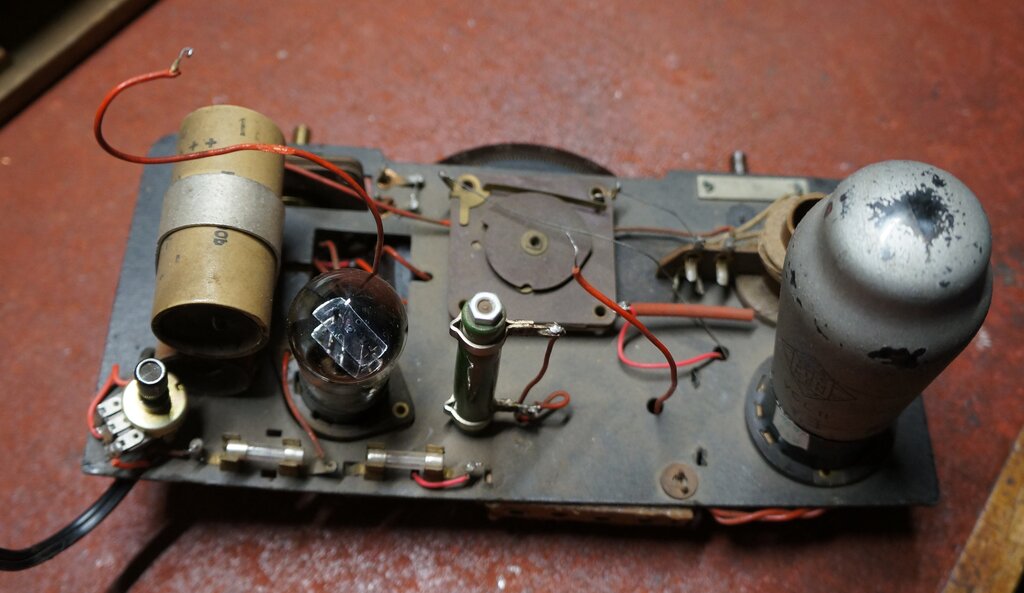
Under chassis restoration complete.
Speaker Polarity.
Where direct current flows through a speaker
or headphones using permanent magnets, polarity is important. If connected
so the magnetic field aids that of the magnet, all is good. If connected
so the magnetic field repels, the magnet will be weakened over time.
The DKE speaker has polarity markings.
If there were no polarity markings, the way to test it is to see which
way the cone moves with the application of DC. The voice coil or diaphragm
should be drawn towards the magnet when polarity is correct. I wonder how
many of these sets have weakened speaker magnets because the polarity was
not observed during restoration.
Note the "+" symbol. This is connected to the B+ supply.
Two of the clamps securing the speaker to the cabinet were missing, but easily reproduced. Conveniently, the screws are M3.
Grid Emission.
Unfortunately, I became aware of the plate
current gradually creeping up, and the need to readjust the trimpot. This
looked like grid emission. High gain power valves are prone to this, since
their cathode operates at a high temperature, and the grid is very close
to the cathode.
It becomes more problematic the higher
the grid resistor is. In this instance 1.5M is rather high to start with.
Generally, it should be no higher than about 470k, and preferably lower
if possible. Another consideration is how old these valves are now, and
the possibility of an imperfect vacuum, which only exacerbates the situation.
I had checked the grid coupler on a 500V Megger tester, and it was perfect with no leakage. To be certain, I replaced it but the grid bias still dropped over time. Then after a longer period of time, a hum developed. I found that increasing the 1uF back bias bypass to 47uF eliminated it, but that was just masking the fault. It appeared the VCL11 also suffered heater to cathode leakage. With a heater voltage of 90, it's perhaps not surprising that it would be a difficult valve to keep hum out of. It's a lot harder to prevent hum radiation or leakage at 90V than at 6.3V!
The Telefunken VCL11 was confirmed faulty
when I tried another (made by Valvo). Not only was the hum gone, but the
sound quality was even better, and more what I thought it should be. Alas,
the Valvo VCL11 also suffers from grid emission, although not enough to
make it unusable. Bias is around -8V for 12mA plate current. The Telefunken
VCL11 could still be pressed into service, if the grid resistor was reduced
to the minimum - about 200k before the gain would noticeably drop off.
Doing so would possibly require the coupling condenser to be increased,
to retain the low frequency response. The back bias bypass capacitor would
have to be increased to eliminate the hum - or operate the heater from
DC.
Of note was that the Valvo VCL11 took
considerably longer to warm up. It took something like a minute, with the
heater voltage increasing very slowly from cold. It was also noticed that
the cool down time was longer than normal. This suggests a different construction
of the heater with a lot more thermal mass - possibly a result of improved
heater to cathode insulation.
Inside the back. Note the two new speaker clamps.
The notion that the DKE is deliberately designed not to pick up distant stations is completely false. While in terms of RF voltage fed into the aerial terminal, it is obviously not as sensitive as a superhet, a good aerial makes up for that. A high gain receiver with a low gain aerial, vs. a low gain receiver with a high gain aerial ends up with much the same receiving ability.
Back cover in place with new M3 screws.
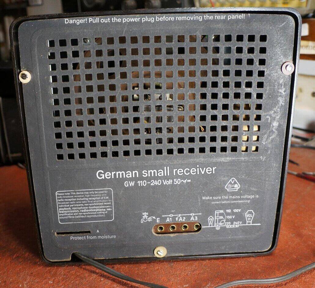
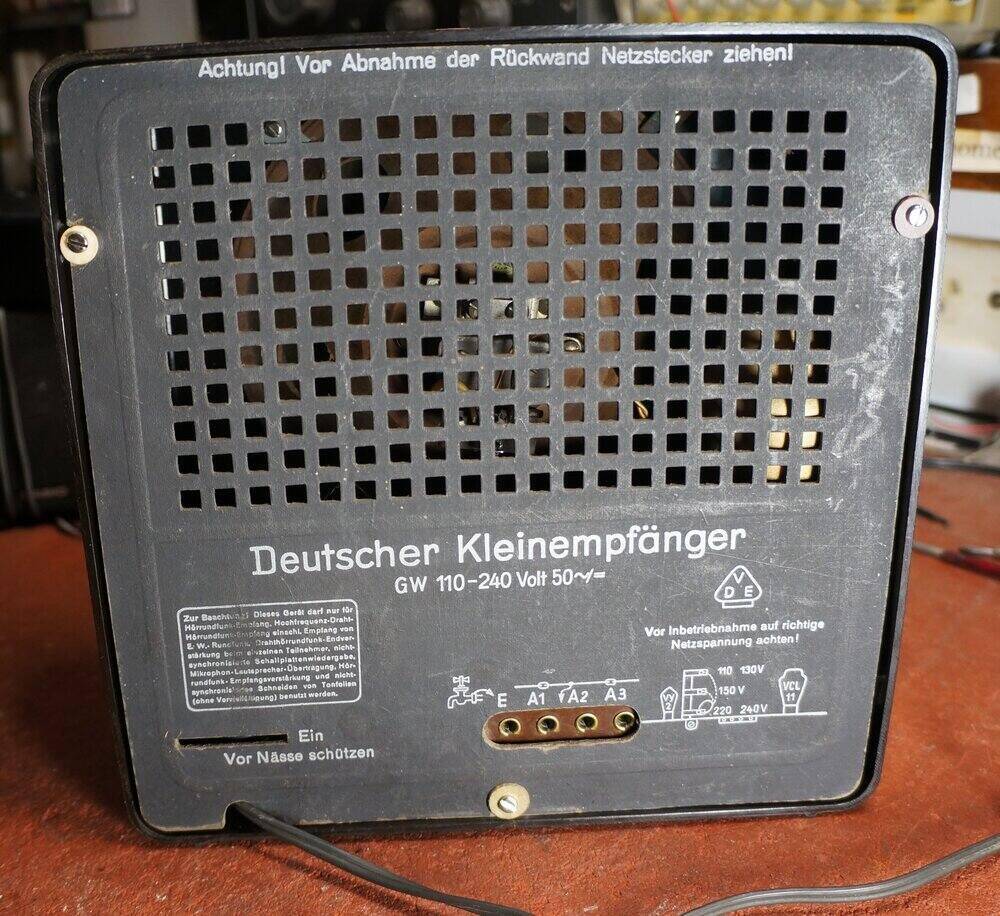
Back translated to English. "Ein" should have been translated to
"On", since this is where the power switch was in the earlier models.
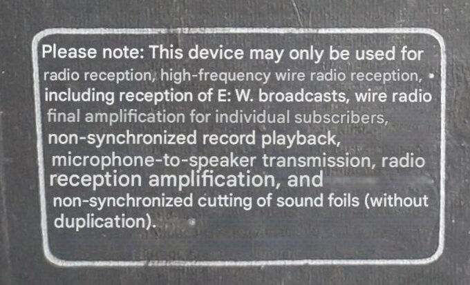
Close-up English translation of bottom corner. One wonders, after
that exhaustive list of permitted uses, what else could it be used for?
The source of the 'working' VCL11 was this wooden cased receiver. It appears that this receiver is built to a lower cost of the bakelite version. The cabinet is of very rudimentary construction, reminiscent of something home made. The back of the cabinet was cardboard, cut from that of another receiver of "Orion" brand.
Note the horseshoe speaker magnet. Chassis supported on foam block.
The chassis is nothing more than cardboard. Unfortunately, after many years it can no longer support the components mounted thereon, and has developed a severe sag. It has been propped up on a foam block visible under the aerial terminals.
It appears someone has completely rewired the set , and many of the components have been replaced. Not surprisingly, the VY2 has been bypassed with a silicon diode. This is a later version with a filter resistor instead of a choke. It is not clear if it's original or not, but there are only two aerial terminals, instead of three. The A2 connection is missing. Our would be restorer has also connected a capacitor between the earth terminal and the B+ negative.
Two fuses are present. The replacement
dropper resistor is fixed at 3k, which would suggest the heaters are being
under run. The 4uF filter condensers are still present, although not connected.
With the wiring all the same colour, it is difficult to trace out the circuit.
At this stage I have no plans to restore
this set, but I did power it up after reconnecting the second electrolytic,
which had one connection floating in mid air. Performance was abysmal.
There is obviously some fault present. It was able to receive a nearby
airport beacon on LW, and one of the high power 50kW ABC stations about
50km away, but the volume was a fraction of what it should be.