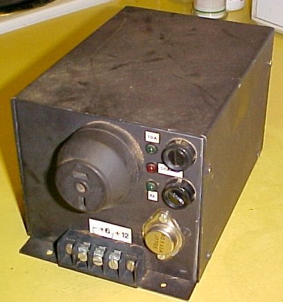
Front view of converter shows 12V output socket, terminals, fuses and switching transistor.
Front view of converter shows 12V output socket, terminals, fuses
and switching transistor.
This project came about as the Model T
is equipped with a six volt electrical system and I'd bought a small air
compressor for tyre inflation that only worked on 12V. Having said that,
the more heavy duty model of the same compressor does in fact work quite
well on 6V. The higher the motor current of a 12V motor, the more likely
it will work satisfactorily on 6V.
Of course this unit can be used to power
other things; for example a Peltier effect car fridge, CB radio, mobile
phone etc.
Commercially made Converters.
6 to 12 volt converters have been a commonly
available commercially made product in the past. During the 1960's and
70's there were still many 6 volt cars in use, but most solid state car
radios and tape players were 12v only and so there existed a need for these
converters. Particularly common were VW Beetles up to 1966, and it's at
VW swap meets where such converters will often be found. Usually they sell
between $2 and $10. There's not a great demand for them these days, as
unfortunately many vintage cars have been converted to 12V. New ones can
still be purchased from some Model T parts, and other vintage suppliers,
but they're considerably more expensive. And of course, 2nd hand ones appear
on Ebay.
The design is much the same across the
different brands. In Australia, the Japanese "Bellsonic", once sold
by Dick Smith was particularly common. They use a two transistor oscillator
driving a step up transformer (often a ferrite toroid) with the same
transistors rectifying the stepped up voltage by means of their base emitter
junctions. The load current flowing through the base emitter junction gives
rise to a certain advantage. It is possible to arrange the converter to
automatically start when the load is turned on, thus obviating the need
for a switch on the converter. The Bellsonic unit is however, manually
switched, because there is a bleed resistor and pilot light permanently
across its output to assist with regulation. It is designed for under
dash installation where it's easily accessible.
Generally, the output is around 2A, although
I have one from a Porsche which provides about 6A.
As my compressor draws much more than
this, the commercially made units weren't really suitable for my needs,
hence the design you see here.
Designing a 6 to 12V converter.
Initially, I tried duplicating a typical
commercial unit by winding various transformers and experimenting with
differing methods of driving the transistors, but didn't really improve
on the commercial models. There was a 6 to 12V converter design published
in Electronics Australia during 1974 using an iron cored Ferguson transformer
which helped to understand the operation, but it was becoming clear that
to be able to draw say 8A at 12V would mean an input current of at least
16A at 6V. That's a lot of current and when one takes into account things
like transistor saturation voltage at that sort of current and the fact
we have only 6V to start with, a different approach was called for. One
important thing to consider was that the converter was only going to be
used for short durations with the high current loads; a few minutes to
pump up the tyres, or half an hour with the car fridge.
So why not use a small sealed lead acid
battery to supply the heavy current, but charge it at a lesser current,
which a simple converter can handle during its idle period? As it happened
I had a pair of 12V 4.2Ah SLA batteries looking for a use.
The idea worked out very well, and the
converter has been in operation since 2003.
The converter would have to be as small
as possible given lack of space in the Model T. The logical place for it
would be under the front seat. With not much space and the batteries in
the same enclosure, the design would had to be simple. While the idea of
one of my beloved vibrator power supplies and a home wound transformer
were tempting, the unit would be too bulky. And a vibrator supply on its
own had to be ruled out immediately; the switching contacts are only rated
at around 4A, meaning less than 2A for a 12V output, with efficiency taken
into account.
The Circuit and How it Works.
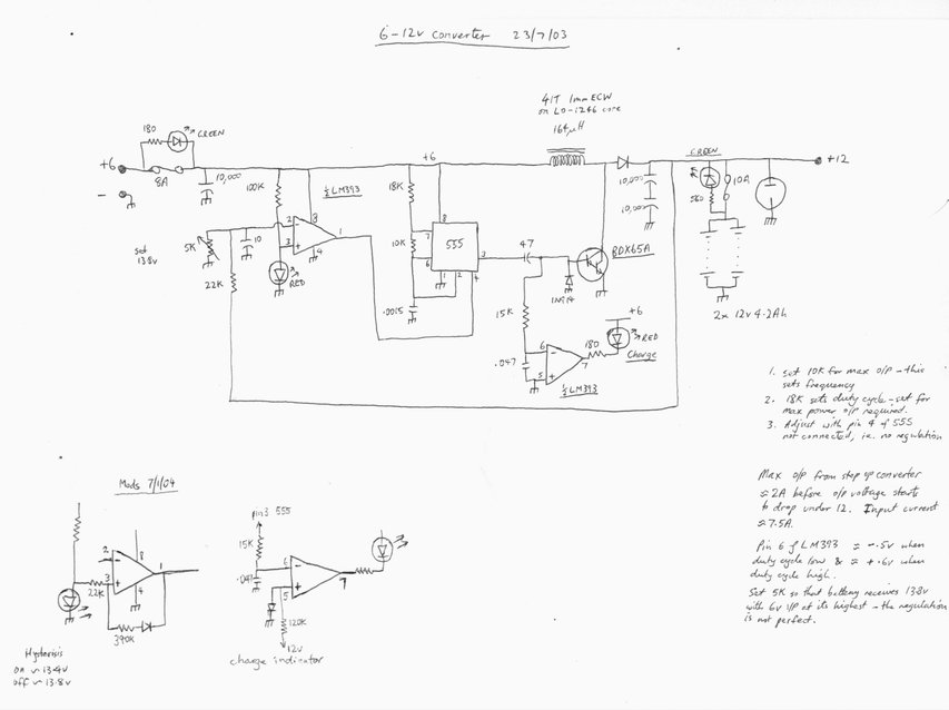
The circuit is essentially a simple switching converter to provide a voltage step up which provides 13.8V to charge a small battery. When the battery voltage reaches 13.8, the converter shuts off.
Step up circuit.
The incoming 6V supply is protected by
an 8A fuse. This is necessary in case the switching transistor shorts out,
which is the normal mode of failure with semiconductors. Filtering to reducing
incoming spikes, and ripple going back into the 6V supply, is performed
by a 10,000uF electrolytic condenser.
At the heart of the converter is the 555
oscillator. The frequency and duty cycle of the square wave output at pin
3 is set to provide the maximum current and voltage output from the converter.
These parameters are largely determined by the characteristics of the 164uH
choke. I used a ferrite toroid wound with 1mm copper wire for this.
When the BDX65A transistor is switched
on, current flows through the choke and builds up a magnetic field. When
the transistor turns off, the magnetic field collapses, creating a voltage
somewhat higher than the supply. It's standard solid state voltage converter
design. This higher voltage is rectified by a high speed power diode and
filtered by 5,000uF of capacitance.
Capacitive drive is used for the BDX65A.
As it's a Darlington type, not a huge amount of drive is required to ensure
saturation. Using capacitive coupling from the 555 means that if the oscillator
fails, the transistor cannot be permanently switched on. (Some commercially
made switchmode supply designers could take note of that).
When the output of the 555 goes high,
current flows through the 47uF and into the base. When the 555 output goes
low, the 47uF discharges through the 1N914 base diode and ensures the transistor
is cut off. This provides a clean switching waveform.
Unloaded, the output will rise to over
20V. The converter needs circuitry to prevent this as it would cause the
battery to be overcharged, damage loads connected to the converter, and
the converter would continuously run, always draining the car's 6V accumulator.
Regulation.
An LM393 comparator is used to sense when
the DC output reaches 13.8V. The output voltage is sampled and compared
with the voltage reference, which is a red led. Leds make good voltage
references because they are stable at around 2V and don't require much
current. If the voltage at pin 2 of the LM393 rises above 2V, pin 1 will
go low and shut off the 555. The converter then stops and will not restart
until the voltage has fallen again. This rapid turning on and off results
in an average voltage of 13.8 across the battery.
A later improvement as shown was to introduce
a degree of hysterisis with the comparator. This was because the converter
never really shuts off and was putting a small but constant drain on the
6V supply. A small amount of positive feedback was provided by the 390K
and 22K. The 13.8V now has to fall to 13.4V before the converter switches
on.
What happens now is there is a short burst
of about a second every few minutes where the battery is kept topped up.
Of course, as the 12V output is drained
the converter runs for a longer period, and with high loads runs continuously.
Charge Indicator.
To indicate the operation of the converter,
a red led is driven by the other half of the LM393. The negative input
is fed from the base of the BDX65A via a simple isolating resistor
and capacitor filter. When the transistor
is being driven, there exists a small negative voltage at the base due
to the 1N914. Thus the LM393 turns on, driving the led.
However, it was found that the led wasn't
always switching off when it should, and jacking up the positive input
by 600mV solved this. This meant there really had to be a definite negative
voltage at pin 6 to activate the charge led.
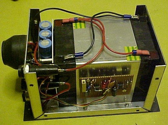
Inside the unit. The circuit was built on a piece of Veroboard.
The choke is mounted on the panel under the three electrolytic condensers.
Output.
In view of the battery load, the 5,000uF
filter capacitance might seem superfluous, but it serves two purposes.
First, to keep ripple down as the battery ages, and secondly for the setup
adjustment it's easier to run the converter without the battery to set
the voltage trimpot, so something is needed to filter the output.
On its own without the battery, continuous
output is around 2A at 12V. However, it shouldn't be used like this because
of the constantly changing voltage output. Unlike other switchmode supplies
which vary the duty cycle of the switching waveform, this one simply drives
at full output until the maximum required voltage is reached, then switches
off until it falls beyond a slightly lower point. This was done for simplicity.
While the duty cycle of a 555 can be varied by controlling the voltage
on pin 5, this also varies the frequency and reduces efficiency in the
choke circuit.
The battery is fused before it reaches
any other circuitry or the outside world. As with the input fuse, led indicators
show blown fuses. I thought this was a good idea as when out in the car
and something goes wrong it means one can narrow it down at a glance rather
than having to get out a test lamp or meter and start pulling things apart.
Construction.
I built up an aluminium box to fit under
the front seat. This also houses the two 12V 4.2A SLA batteries. On the
front are all the led indicators, fuses, and terminals. I provided a two
pin polarised socket of the type used in the house for the home lighting
plant, to which the 12V appliances can be plugged in. The unit is permanently
connected to the 6V accumulator in the car and runs even when the battery
isolation switch is off. There is another 10A fuse in an inline holder
to protect the always live supply to the converter.
As I've pointed out elsewhere, it is essential
not to let lead acid batteries discharge as they will be permanently ruined.
Apart from natural self discharge, there is a 500uA drain from the voltage
sensing circuit. While I always have the 6V accumulator connected to a
maintainer when at home, there is no problem with the converter discharging
it over several days away from home.
Operation.
This is completely automatic; one simply
uses the 12V load as required. However, due to the actual converter circuit
only being able to provide about 2A, one can see if more than this
is drawn, the SLA battery will discharge. With a 4A load one could, in
theory, run the converter for about four hours before its internal battery
is flat.
The other thing to keep in mind is the
charge rate from the car generator. I've set this to 5A, but at full output
the 6 to 12V converter pulls 7.5A from the car battery. With 12V loads
under about 2A, one can drive all day without anything discharging.
In practice, these limitations have not
caused any problems. The tyre compressor is only run for a few minutes,
and a trip to the shops and back with the 4A car fridge is less than an
hour.
Has anyone spotted the potential advantage
of incorporating the SLA battery? Well, it means that if the 6V car accumulator
was completely flat or faulty and one was away from home, then a jumper
wire can be run from the 12V terminal to the coil box and one could continue
driving. The CB radio or mobile phone is also not put out of action.
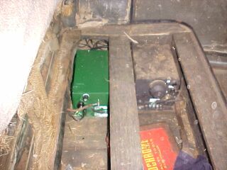
6 to 12V converter mounted under the front seat next to the radio.
While the converter worked well, it did require replacement of the SLA batteries after a few years. Given the cost of these, I eventually decided to replace the converter with a commercially made unit which can provide 6.3A at 12V. It appears to have been made in Germany and intended to be used in a Porsche. It can run the tyre compressor under load.