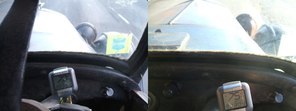
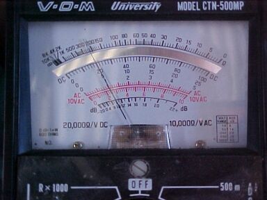
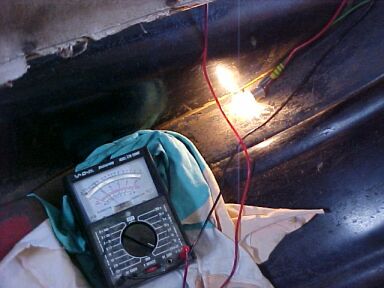
Here we see speeds of 70 and 75km/h are attainable in a Model T Ford with the original four coils powered from the 6V electrical system. This car does not have a magneto.
One of the challenges often faced by the Model T owner is a faulty magneto. Unfortunately, this usually leads to the installation of some other form of ignition system, usually a distributor. There seems to be an underlying assumption that a Model T can only be used with its original four coil ignition system, if it has a functioning magneto. This, in actual fact is not correct, and the existing 6 volt electrical system is quite sufficient.
Here we see speeds of 70 and 75km/h are attainable in a Model T
Ford with the original four coils powered from the 6V electrical system.
This car does not have a magneto.
Background to the Model
T ignition system.
The Ford ignition system comprises four
separate ignition coils, each with its own vibrator contacts. These are
connected directly to each of the four spark plugs. As to which spark plug
is firing at any given time, that is determined by switching the low voltage
supply to each coil in turn. This is done by a device called a "commutator"
or "timer". It is mounted at the end of the camshaft and is essentially
a four way switch. Similar to a distributor, but it switches the low voltage.
The supply for the ignition coils comes
from either a magneto or a battery.
Much has been written on the subject in
various Model T literature and on the Model
T Forum. Suffice to say, the magneto provides about 6 to 30V AC, the
voltage and frequency dependent on engine speed. Because of how the coils
operate, and the waveform produced by the magneto, the ignition timing
operates differently when operating on the magneto than when on battery.
The Ford coils also can operate on a battery.
This is the 6 volt accumulator in the 1919-1927 cars. Prior to this, the
battery was optional and could consist of a number of different types,
a dry cell "Hot Shot" (similar to a modern day 6V lantern battery), a collection
of No.6 dry cells making a 6 or 9V battery, or a 6 or 12V storage battery
- this being more likely if the car had been updated to include electric
lighting.
The battery option was provided in the
1909 -1919 cars simply because unless the magneto is perfect the car is
much easier to start on battery. The continuous spark helps apart from
the battery voltage being higher than what comes from the magneto when
turning the engine by hand.
Prior to the Model T, cars like the Model
N which used the four coil and commutator system ran on battery only, although
there was an accessory dynamo which was available from 3rd party suppliers.
However, the problem was dry cells can't
be recharged and no means was provided to charge storage batteries in these
cars. So, it was an inconvenience having to replace dry cells all the time,
or to take the storage battery to a garage to be recharged. Needless to
say, some drivers were stranded with flat batteries.
One of the improvements that the Model
T was to include, was not to have to rely on a battery at all. This is
where the flywheel magneto comes into the picture. 16 magnets mounted around
the flywheel induced current to flow in adjacent coils mounted on the back
of the engine block.
Magneto problems.
Unfortunately, the idealistic design has
a number of disadvantages. Over time the magnets weaken, with the vibration
and hot temperatures assisting with their deterioration. So, although not
approved of by Ford, methods were developed to recharge the magnets in
the car. The distance between the magnets and field coils is critical.
Too close and they hit each other at 2000 rpm resulting in broken magnets
and damaged field coils. Too far apart, as happens when the 3rd crankshaft
bearing wears, and the voltage decreases making for weaker ignition. Sometimes
the magnets are cracked and eventually fly apart.
Then there's the field coils themselves.
These are prone to short circuits. All that hot oil is hard on the insulation.
Sometimes it flakes off and metallic particles become embedded between
turns of the copper coils, reducing output in varying degrees. In some
cases, the coils detach from the bobbin plate and once they come into contact
with the magnets, there's several metres of copper ribbon wrapped around
the flywheel and transmission.
The worst aspect of all this is that the
engine has to be removed to service most faults with the magneto.
In my opinion, it is one aspect of the
Model T design that could have been improved. The external dynamo of the
Model N would seem to be a better idea.
My own car.
The magneto in my own car was partially
operative when I got it, but output was too low to run at idle. I had noticed
damage to one of the field coils where attempts had been made to remove
the starter motor without removing the Bendix first. Apart from this, attempts
to remagnetise the magnets in the car did not work. This was right
at the start of my Model T learning curve back in 2002. I had seen messages
in the Model T Forum that the coils wouldn't operate properly on 6V at
driving speed, and that a 12V supply would have to be used or a distributor
ignition system used. Neither option were acceptable for my car.
But, as it turned out, my car seemed to
operate perfectly well with 6V powering the coils, and other club members
who drove it said that it "drives just like a typical T". And so, I stopped
worrying about the inoperative magneto.
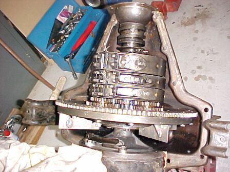
When I rebuilt the engine in January 2010,
I removed the magneto and replaced the magnets with commercially made paddles
to keep the oil circulating function. As it was, the coil insulation had
deteriorated on a number of coils and there was miscellaneous damage from
various objects that had fallen into the transmission. It was no wonder
that recharging attempts failed.
I thought long and hard about restoring
the magneto, but ultimately, the magnets would still weaken over time,
they could still break off at 2000 rpm, and the coils could still detach
themselves making a mess. Plus, I'd driven the car for over seven years
without it and wouldn't miss it. Not only is the flywheel so much easier
to work on, but service access in the transmission is so much better. The
lighter flywheel should also prolong the life of the 3rd bearing.
Regarding the paddles, I used the ones
from Texas T Parts as they were braced against bending. However, the supplied
ring gear bolts cannot be used as they will only jam up and break. Someone
has stuffed up somewhere and there's now three sizes of repro ring gear
bolts doing the rounds.
No magnets to break off, no field coils to come apart, and much
better service access!
The original bolts are #14-24, but one
of the repro parts manufacturers interpreted this as 1/4" -24. Hence we
have two kinds of repro ring gear screw in circulation. Some repro ring
gears are tapped for the 1/4" thread. Some of the oil paddle kits come
with 6 mm screws, and this is what I've used. It is important that the
paddles are made of steel and braced as shown. There have been stories
of unbraced paddles, especially aluminium ones, breaking off. There is
a lot of force against them when the oil is cold.
6 mm x 1 mm screws fit perfectly for the
ring gear and will self lock; the difference in pitch being just enough.
However, they must be high tensile screws or this self locking function
won't work. I notice the kits providing 6 mm screws also provide a 6 mm
tap. I'd be hesitant to use the tap as the screws won't be as tight, and
I'd also check the screws are in fact high tensile.
Running on battery.
Why have some owners said that Ford coils
won't work well on 6V at speed? Invariably, these claims have come from
Model T owners who have used a "timing gauge" to set up their initial timing,
or from those who are using non rebuilt coils, with an ignition system
in average condition, or poor performing spark plugs.
The importance of ignition timing is that
with a low supply voltage, the points take longer to open at 6V than they
do at 12V, or the higher voltage provided by the magneto. The result can
be retarded timing. At 6V, the coils take 3.5ms to fire. On 12V, they take
2ms. 12V has been found to be, from dynamometer testing, to be equivalent
to magneto operation in terms of the car's performance. So, it can be seen
that at high speeds where advance is needed, 6V performance will lag behind,
if
the same timing settings are used. For this reason, there is an
assumption that if battery operation is desired, the battery needs to be
12V. However, my testing and experience has proven this not to be so.
It needs to be pointed out that when the
car is running at speed, that the coil supply voltage is actually closer
to 7V because of the generator charging.
To operate Ford coils successfully on 6V, several requirements must be met, and having said that, everything must be 100%. First, the coils must have new capacitors in them, and they must be the right kind or they will fail. It is amazing what I have seen installed in coils, from 1uF electrolytics to .1uF 400V paper. Needless to say, the owners of them claimed the Ford coil system was incapable of operating properly, and subsequently fitted distributor ignition. 12V operation will often mask faults in defective or misadjusted coils simply by brute force. Once the owner has found that the ignition system appears to work properly with 12V, having masked a defective set of coils, poor timer, or weak spark plugs, the conclusion is come to that 6V will not operate the coils properly.
The coils must to be adjusted correctly, for equal firing time. For this, I designed an electronic coil tester as described here. The ECCT is a commercially available coil tester that also tests for equal firing time. If the coils are set using a "buzz box", or hand cranked coil tester, there is no way of knowing exactly when the coil fires after the timer makes contact. Thus, there is the possibility that the cylinder to cylinder timing is not consistent.
Next is the timer. Roller timers do not
provide a reliable low resistance path, especially at 6V. There are multiple
connections between moving parts, and the roller is prone to bounce as
the contacts and insulating material in the timer case wears. An Anderson
timer provides positive and reliable contact. Also available is the TW
timer. Both these timers make a positive contact throughout the switching
time. However, the Anderson, while of much lower maintenance, does suffer
from timing variation as it wears. I have not tried a New Day timer, but
it would appear to be suitable.
For the spark plugs, Champion X or similar
are essential. I have used Lodge spark plugs with excellent results. The
worst were KLG's and modern plugs with 14mm adaptors.
Initial Timing most important.
An important thing to note is the initial
timing. That is, the firing time ATDC with the timing lever fully up (retarded).
It appears that some owners in the U.S. set the initial timing to 15 degrees
ATDC, because of the availability of a so called "timing gauge". The purpose
of so doing to prevent any kickback when starting on magneto.
For the Australian assembled Canadian
cars, being right hand drive and with the timing adjusting linkage being
quite different, no such tool is known to be available and it has been
customary to set the initial timing for just after (2 degrees) top dead
centre. In the absence of any defined adjustment, it is the most logical
because it provides the full range of timing control. It is mainly for
this reason I had immediate success with 6V operation.
This effectively gives 13 degrees extra
advance over cars that have been adjusted with the timing gauge. Conveniently,
this happens to compensate for the slower firing time of coils on 6V.
With everything set up thus, I can often
get over 75km/h. This is quite sufficient for a Model T. While higher speeds
are possible at times, the risk of breaking something worries me, so I
keep to 75 or below. Also of course, are the extra stresses on the car
if it has to be stopped quickly at that speed.
Requirements for successful 6V operation:
Further Experiments.
In learning about coils running from battery
alone, I have experimented with running them from 9V DC and have spent
some time driving this way. I was not keen on 12V as this causes a shortened
point life, as the blackened points I've replaced on coils so used demonstrate.
Nevertheless, for the sake of completeness in testing, I have tested performance
on 12V short term, by means of a SLA battery to power the coils separate
from the car's 6V electrical system. No more will be said about 12V operation
because I found no real difference between it and 9V. 9V effectively gives
12V performance, but without the points damage.
For long term testing, I created two adaptors that provide 9V, which I describe here. The first one was generator based, making use of one of the interesting properties of the 3rd brush generator used by Ford.
Obtaining 9V from the
Generator:
The Model T generator, being of the 3rd
brush type is a constant current source and will put out much more than
6V if it's allowed to. So was there some way I could use this property?
It's really quite simple. Let's say the
generator is set to 5A. That 5A remains fairly constant over a reasonable
voltage range; certainly up to 9V which is all I'm after. 9V was chosen
because it gives ample advance, but without the amount of points arcing
and deterioration which occurs on 12V.
Simply by connecting a resistor between
the generator and battery we can increase the generator voltage while still
charging the 6V battery at 5A.
Rough calculations indicate the resistor
should be 3V/5A, or about 0.6 Ohms. Simply putting this resistor in the
wire between the ammeter and cut out will provide us with 9V when the engine
is above idle speed. So easy! There's a few refinements however:
The circuit and how it
works.
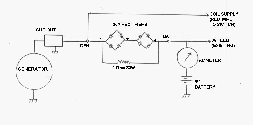
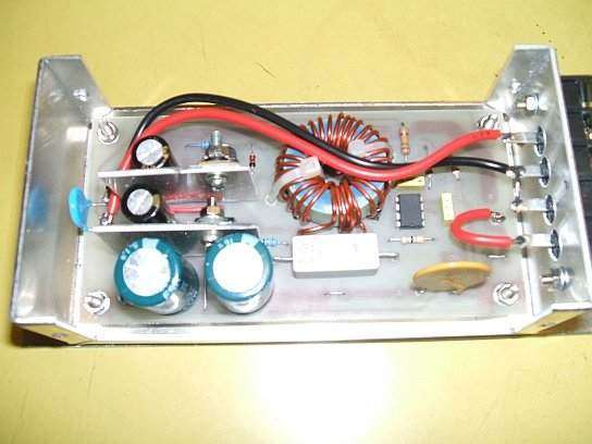
Only two rectifiers and one resistor make up the circuit. It keeps
in with the theme of simplicity inherent to the Model T.
While a simple resistor will work, the
problem is the value is critical, and the charge rate is not perfectly
constant. So, what we need is a device with a constant voltage drop, regardless
of current flow. Silicon diodes are ideal, with a drop of around 600-700mV.
They're easy to get, and for high power applications like this, you can
use 35A bridge rectifiers. Used as voltage dropping devices, a bridge rectifier
can provide the drop of two diodes, or about 1.2V. Note that diodes also
provide a fail safe function. If only a resistor is used and it burns out,
the generator could be damaged as well as anything connected to the boosted
supply. Diodes fail short circuit, so if this happens no harm will come
to anything, and the 9V supply will simply drop but not fail altogether.
SImply add further rectifiers to get the
required voltage. If you only need a 600mV drop, then use only half the
rectifier bridge.
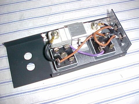
Unit before the perforated cover installed.

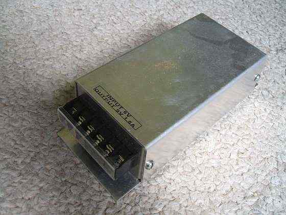
Unit ready for installation in the car.
The bridge rectifiers I used have a diode
drop of 750mV at 5A, so two rectifiers give 3V drop. Perfect. Obviously,
the diodes must be rated at a higher current than the charge rate. For
reliability, 35A ones are the best with ample reserve. Mounting is easy
with a single 4mm hole.
Now, let's analyse the operation but first
assume the coils are running off the 6V battery as normal. The car starts,
and as engine speed increases, the generator voltage increases. At about
8V, the cut out closes and current starts flowing through the 1R resistor.
Not the full 5A, but still some current. As generator output comes up to
9V, the diodes start conducting and there is now a constant 3V drop between
the generator and battery. 5A now flows into the 6V battery via the ammeter,
and the battery charges normally. Now, look at the "Gen" terminal of the
circuit. Because we've added 3V onto the battery voltage, we have 9V at
this point. The red switch wire (that used to go to the magneto) is connected
here, and with the switch in "Mag" position, the coils now receive 9V DC.
Engine above idle. The reason we have 10V is because the battery
is 7V when charging. This drops back to 9V when the headlights are on.
The brilliance of the 12V test lamp is further indication of the success
of this circuit.
So, we switch to "Mag" and happily drive
along at high speed with 9V to the coils. At some point we have to slow
down and let the car idle.
What happens now is the generator voltage
is less than the battery voltage. The cut out has opened, so no supply
from the generator. At this point the coils would be deprived of power,
as the diodes are not conducting in the reverse direction. This is where
the resistor comes into operation.
Current from the battery flows through
the resistor and to the coils. Because of the resistor's presence the coil
voltage will now be a little less than 6V, but as the engine is only idling
that's not important.
The value of resistor is not super critical.
It must be high enough to allow at least 3V drop at the required charge
rate, but it must also reduce coil voltage at idle by the minimum amount.
I can't see anyone charging at less than 5A, so 0.6 Ohm is ideal. 1 Ohm
is close enough.
Next thing is what kind of resistor to
use? Ignition coil ballast resistors are ideal. Easy to mount, high wattage,
and very rugged. They are also of the low resistance required. I found
that what the label says isn't always accurate. I bought several RU51 resistors
which were claimed to be 1.6 Ohm. One measured 1 Ohm which is what I used
in this circuit. It is possible to reduce the value as the resistance wire
is just screwed under the terminal bolts.
Keep in mind that the wattage rating decreases
proportionally when doing this.
And what power does the resistor dissipate?
P=IV. Assuming 5A charge rate, it's 15W.
Limitations.
The circuit will work only with the electromechanical
or diode cut outs. It will not work with the Fun Projects or any other
voltage regulator. Voltage regulated generators (or alternators) will not
work, as they function as constant voltage sources.
Keep in mind the power rating of a Model
T generator is about 100W. The fact it's now outputting 9V (10V on charge)
derates the current that can be drawn.
Power dissipation of the resistor and
diodes needs to be considered and efficiency reduces as charge current
increases. As an example, for a 10A charge rate, about 30W minus the coil
power is going up as heat. I find 5A quite sufficient and have never had
a flat battery despite driving at night or using the radio.
Installation.
The unit installed under the floor. The two pin socket is for the
brake light switch attached to the upper floorboard.
Given the lengths of wires from the harness,
I mounted the unit on the right hand side body rail under one of the existing
bolts. This is a RHD car.
The only new wiring is one wire to go
from the adaptor to the ammeter/battery terminal on the terminal block.
Because I'm using a LHD wiring harness mirror image fashion, the original
generator wire couldn't be used anyway so I'd already made one up previously.
The length of this was already suitable for the adaptor.
Switchmode 6 to 9V converter.
Some problems were observed with the adaptor
circuit previously described. One limitation is that the coils can run
on insufficient voltage at low engine speed. What happens is that when
the engine is going slow enough that the cutout opens, the coils are running
on the battery voltage, minus the voltage drop across the resistor. This
can cause erratic firing. In the worst case scenario, going up a hill in
top gear with the headlights on, the voltage fed into the coils could be
as low as 5V.
Another limitation is that I was given
a Fun Projects voltage regulator which is incompatible with this circuit.
The correct thing to do was to make a regulated 6 to 9V converter to run
the coils. This would have the advantage that the coils would be fed with
9V regardless of what the generator was doing. Even with the battery down
to 5V, coils would still receive 9V.
The circuit I used is a very typical design
based around the MC34063 switchmode IC.
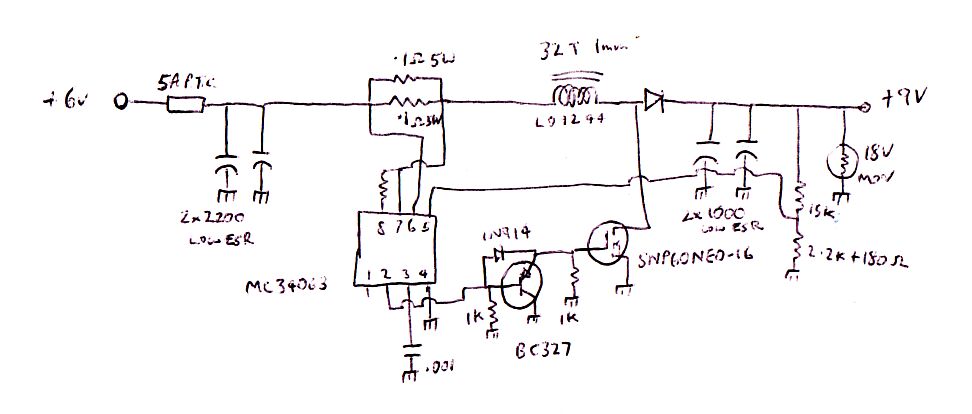
The MC34063 drives a MOSFET in order to
obtain the required output current. I designed it for a continuous 1.5A
output. The MOSFET must be one with a gate voltage of 5V or less given
the low supply voltage. If the MOSFET does not saturate it will overheat
and efficiency will be poor. I used a SNP60NE0-16.
The choke is wound on a Jaycar LO-1244
toroid core. The rectifier is a Schottky type as used in computer power
supplies. Because of the high frequency ripple currents, low ESR electrolytics
are used for input and output filtering. Feedback is provided by the voltage
divider consisting of the 15K and 2.2K + 180R resistors. Changing any of
these resistors will actually allow the circuit to function as a 6 to 12V
converter if desired to run low power 12V appliances.
The BC327 circuit is to speed up the switching
off of the MOSFET to minimise power dissipation.
Protection of the circuit is by a 5A polyswitch
on the incoming 6V supply. This is superior than a fuse, given the likely
possibility of inadvertent short circuits when working on the electrical
system, etc. It has the advantage of being self resetting once the short
is removed. It is necessary in case the MOSFET shorts out, which is the
normal mode of failure. To guard against the spiky back EMF of the coils
getting back into the converter, an 18V MOV is connected across the 9V
output.
Inside the converter. I used the PCB from the June 2003 Silicon
Chip DC-DC converter article and changed components to suit my version.
Enclosed in an aluminium box, the converter easily fits under the
seat.
Performance is excellent. Efficiency is 85%. Typically, for an output of 1.5A at 9V, the input is 2.7A at 5.8V. Note that the coils are not drawing current continuously when the engine is running, so that the average input current is less than this. Standby current is only 3.6mA which means the input can be permanently connected to the battery, provided a maintainer is connected when the car is not in use.
Conclusions - what difference does 9V operation make?
The biggest difference was when I was experimenting
with modern 14mm spark plugs with adaptors. I found running on 6V poor,
with the exhaust pipe glowing red (visible through the handbrake hole in
the floor). Maximum speed was about 65km/h. This was quite different to
the original Lodge spark plugs which performed very well with 6V coil operation.
Alas, the Lodges gradually broke and had
to be replaced. I had used Motorcraft F11 types with some success, but
it turned out Champion X was the best, performing like the Lodge.
So, golden rule is to use Champion X plugs,
or old pink Lodges if you can find them.
Around this time, the car also had carburettor
problems (worn mixture needle and seat). Again, I found it necessary to
use higher voltage, but this was just masking the problem. Once the mixture
needle was turned down to remove the ridge worn into the needle, and the
seat was replaced, the car once again worked perfectly with 6V for the
coils.
Next golden rule is that you won't need
more than 6V if the carburettor is 100%.
With everything in the car 100%, what is
the difference you may ask? Well, not a lot as it turns out. I do a lot
of freeway driving in the Model T because of where I live, so I'm well
acquainted with how fast it goes. What makes more difference than anything
else is the weather - cool moist mornings are the best. There is then no
real noticeable difference between 6,9 or 12V. Once the temperatures warm
up for the afternoon, and the winds come up, there is a drop off in performance.
Switching to 9V will give perhaps a slight improvement, maybe a couple
of extra km/h above the existing 78 odd km/h. For suburban driving at 60km/h
there is no difference at all regardless of weather conditions.
On the down side, coil operation rapidly
deteriorates below 6V. If the headlamps are operating for example, and
the battery is defective, then erratic operation starts to occur. With
the generator putting out only 5A, and the headlights drawing 10A, the
battery voltage can not come up to 6V. However, this is merely indicative
of a faulty battery.
In conclusion therefore, 6V has been proven sufficient to run the ignition coils with good performance. The photos at the top of the page are proof of this. If you like experimenting, by all means try the 9V adaptors presented, preferably the switchmode one, but they're certainly not essential.