This inverter was bought in a box of junk
at an HRSA auction. Not only did I have to have it because it was an inverter,
but obviously it was a vibrator type. It is also the first 32V inverter
to enter my collection.
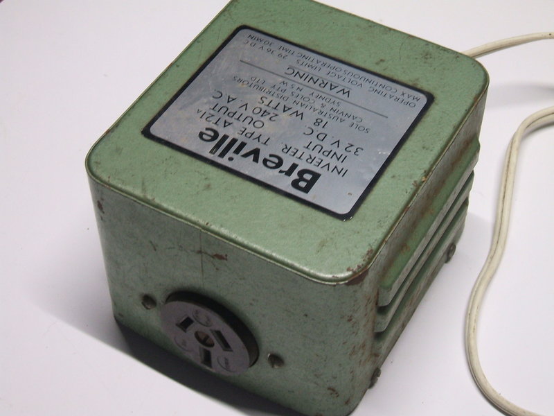
At first glance, it looks like it's based
on some of the Smoothflo designs with the curved cornered enclosure, and
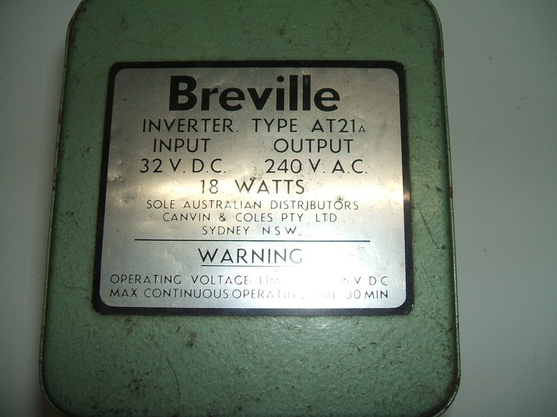
the bottom plate that is always so difficult to remove. Output is 18W at
240V. Input voltage is specified as 29-36V. Mention is made that the inverter
is suitable for a maximum of 30 minutes continuous use. That suggests something
is being operated outside its ratings.
The label on the top gives no clue as to
the operating frequency, but I assumed like other similar inverters that
it would just use an Oak vibrator with a 100c/s frequency. It was something
of a surprise when I opened it to find a German made Kaco 50 cycle vibrator.
Now, while Kaco was a prominent vibrator
manufacturer in Germany, they were not imported into Australia. Here, the
market was dominated by Oak and Ferrocart. Breville would have had to go
out of their way to import the Kaco vibrators. The question is why?
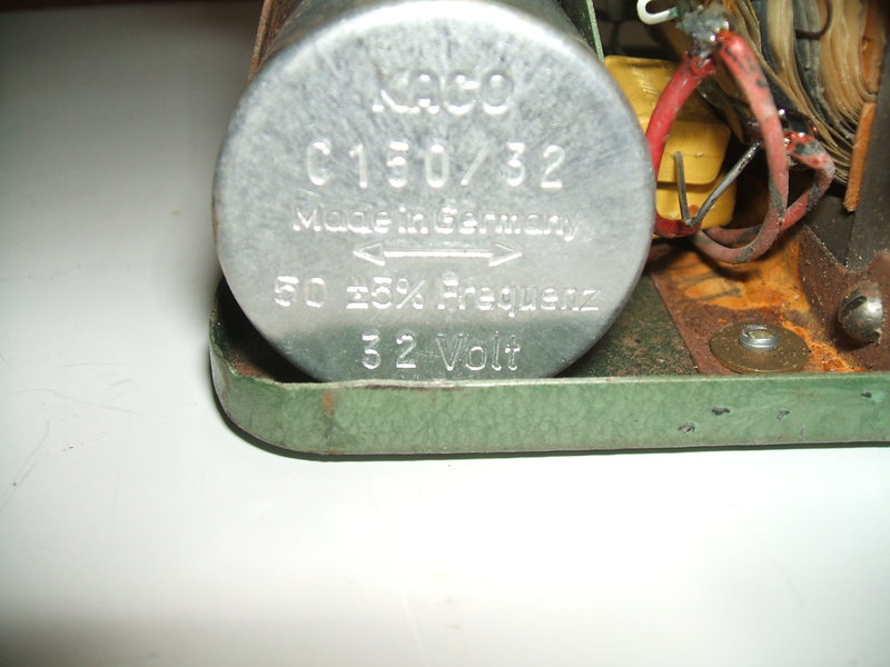
Kaco C150/32 vibrator.
The most likely answer is the need for
a 50 cycle output, and that similar size car radio type vibrators were
not made locally for 50 cycles.
Obviously, the inverter was for a specific
load which was frequency dependent. All the other small Australian made
vibrator inverters described on this site are either 100 cycle or DC. This
suits small mantel radios and AC/DC shavers which is what these inverters
were intended for.
The Breville would most likely be designed
for hair clippers. Breville, of course made such things. Unlike motor driven
shavers, hair clippers rely on a vibrating mechanism, and therefore must
run from 50 cycle AC. The power output (18W) would be about right too.
As well, the rather large buffer capacitor suggested an inductive load.
Subsequent tests proved this to be correct.
Construction.
Cost cutting was clearly a priority here.
The transformer is held in with three rivets, rather than four. The vibrator
has the wires soldered directly to the pins instead of using a socket.
This is especially strange as the vibrator fits a standard octal socket.
The vibrator is held in position by a rather crude "U" shaped clamp.
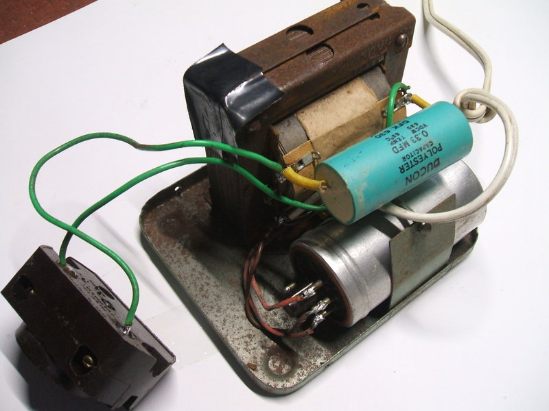
Cheap construction. The capacitors had been replaced before the
photo was taken. The new 0.33uF buffer is shown. Note the wires soldered
to the vibrator pins.
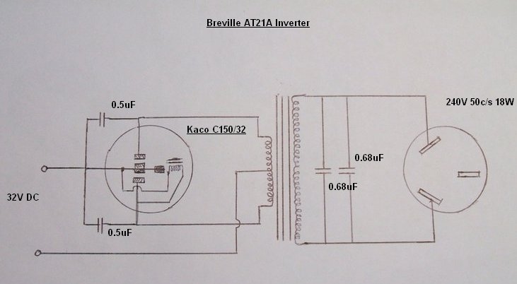
There is nothing unusual about the electrical design, and the circuit is about as simple as it gets. The vibrator is a Kaco CS150/32 which is a shunt drive type with an octal base. One has to wonder why a German company was making 32V vibrators - as far as I'm aware, the ubiquitous 32V home lighting plant so prevalent in Australia was not used there. I can only assume it may have had railway applications - assuming German trains had 32V electrical systems.
A shunt drive vibrator is actually not
a good choice for a general purpose inverter because the reed drive is
somewhat dependent on loading. In the case of a DC-DC supply there is no
problem because the load is resistive and current is drawn only on the
peaks of the transformer secondary voltage. With random inductive and capacitive
loads, this is reflected back to the driving coil and can cause poor or
no starting, or erratic operation.
There are 0.5uF 200V paper capacitors
across the vibrator contacts which would provide some degree of buffer
capacitance, but more likely are there to prevent contact arcing. The absence
of series resistors to limit the current when the contacts close is of
concern.
The main buffer capacitors are two 0.68uF's
in parallel, of 600V rating; one mounted on the transformer tags, and the
other on the output socket. This results in a total of 1.36uF, which I
thought was rather high.
There is no fuse. It is just possible
there was an inline fuse in the twin flex power cable that has since been
chopped off. Given the cost cutting nature of this inverter, I tend to
doubt that however. In fact, I can't recall any shaver type inverter so
far having a fuse. That is most unwise because of the possibility of overloading
the inverter by plugging in unsuitable loads, like a 1kW radiator, or if
the capacitors go short circuit.
Restoration.
First thing of course was to get the vibrator
working. Not surprisingly, being a long disused shunt drive type,
it didn't start. It responded well to the high voltage cleaning method.
I did briefly test the inverter at this point, but it was making very unhappy
sounds and producing awful waveforms. This was to be expected with leaky
paper capacitors still in circuit. In fact, feeding 240V from the mains
via a light bulb, into the transformer secondary, with the vibrator disconnected,
caused the 0.68uF's to get slightly warm.
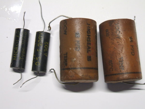
Next was to replace the 0.5uF condensers
across the vibrator contacts. These capacitors were paper "MIcrocaps" dated
1963, which with the vibrator and PVC covered wiring looks about right.
In the case of 6 or 12V inverters, these could be left in situ, but with
a 32V inverter the voltage is high enough for any leakage to be problematic.
The two 0.68uF's were removed. Not surprisingly, they both had about 200K
ohms of leakage when tested on a 500V megger.
All paper condensers were replaced.
Buffer Capacitor.
I temporarily connected 1.5uF of buffer
capacitance across the secondary. With the CRO connected, it was obviously
too much, and the current draw on the 32V side was excessive. It turned
out that on no load, 0.22uF gave the ideal waveform, with an idling current
of about 100mA at 32V.
So what was the two 0.68uF's all about?
Indeed, it was about right for the hair clippers I tried. Being an inductive
load, it is necessary to increase the buffer capacitance. A problem is
that when the inverter is then run with a resistive load, the capacitance
is excessive. It is even more so when the inverter is run with no load.
By the sounds coming from the vibrator and transformer, it would have been
very unwise to run this inverter unloaded. A note should have been included
on the label to warn against this. As the vibrator is very well sealed,
I wasn't going to disfigure it by opening it up to check for arcing. It
certainly sounded like it might be. It was fairly safe to say by now that
this inverter was, a) meant for hair clippers only, and, b) must only be
run with the hair clippers plugged in.
What to do now? The chances of me wanting to use my hair clippers on 32V is zilch, so it was more practical to make the inverter suit more common resistive loads, like light bulbs and portable solid state radio/audio type appliances. The previously ideal 0.22uF buffer is too low for slightly inductive loads, such as those including a power transformer. I found 0.33uF to be the best compromise. Idling current is increased to around 180mA.
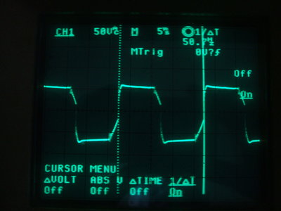
Frequency and voltage measurements. Voltage is measured across the
transformer primary. This is the no load waveform with 0.33uF buffer
capacitance.
As stated in other articles, the buffer capacitance value has to be a compromise for a general purpose inverter. This is because of the different kinds of loads that may be used. The ideal buffer capacitor; that which provides the ideal no load waveform and minimum current draw, suits resistive loads, and loads which draw their current at the voltage peaks (i.e. where the mains is fed into a bridge rectifier such as with switchmode power supplies). With a resistive load drawing current over the whole cycle, the buffer capacitance actually has reduced effect because the load discharges the capacitor faster than it would naturally do so. This is not problematic in terms of excessive voltages appearing, since the loading prevents these occurring. However, input current now flows at the start of the contacts closing, rather than after - as is the case with a correctly operating buffer circuit. In theory this will reduce contact life, and vibrators using in general purpose AC inverters would have a shorter contact life than those used in DC-DC converters. My practical experience over more than ten years seems to indicate this is actually not a problem worth worrying about.
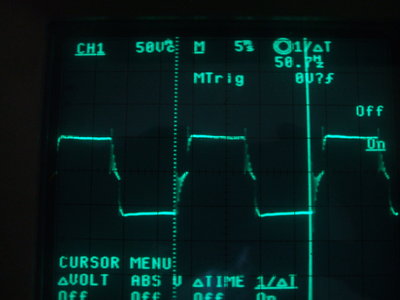
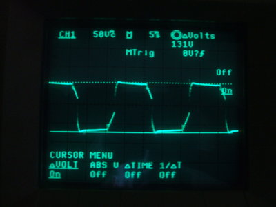
Waveform with an 18W incandescent lamp load. The buffer capacitance
becomes less effective with a resistive load.
When an inductive load is plugged in, the ideal value of capacitance then becomes too small. If a compromise has to made, the capacitance should be higher than normal. This is because too low capacitance will allow excess voltage to occur when the vibrator contacts open, causing arcing and possible transformer insulation damage. Slightly higher than normal capacitance will certainly prevent this, but then the peak current increases, and the timing of the voltage polarity reversal is no longer correct. Given a choice, this is the lesser of two evils. Taken too far however, grossly excess buffer capacitance will also cause arcing and contact damage.
Performance.
The vibrator is undoubtedly the quietest
I have ever heard. It is barely audible. I was surprised that when powering
a solid state AM radio there was virtually no RFI, and this vanished completely
when one side of the 32V supply was earthed. Incidentally, because of the
pulsating current draw, it was necessary to include a 2500uF condenser
across the 32V supply when using a regulated bench supply. Efficiency is
actually very good, with a 15W incandescent lamp load, current draw was
just over 500mA at 32V. The 30 minute maximum run time warning did not
seem to be applicable with the 20W CFL and 18W incandescent light bulb
loads that I tried. The transformer did not run overly warm, and the vibrator
did not make strange noises as they are apt to do when overloaded.
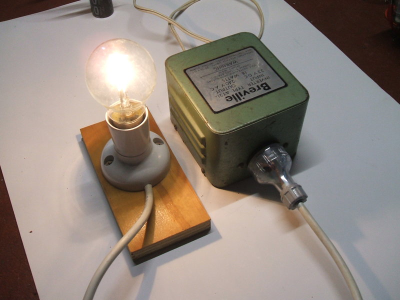
Inverter operating an 18W incandescent light bulb.