From the Australian Ford parts catalog 1927. This can be downloaded here.
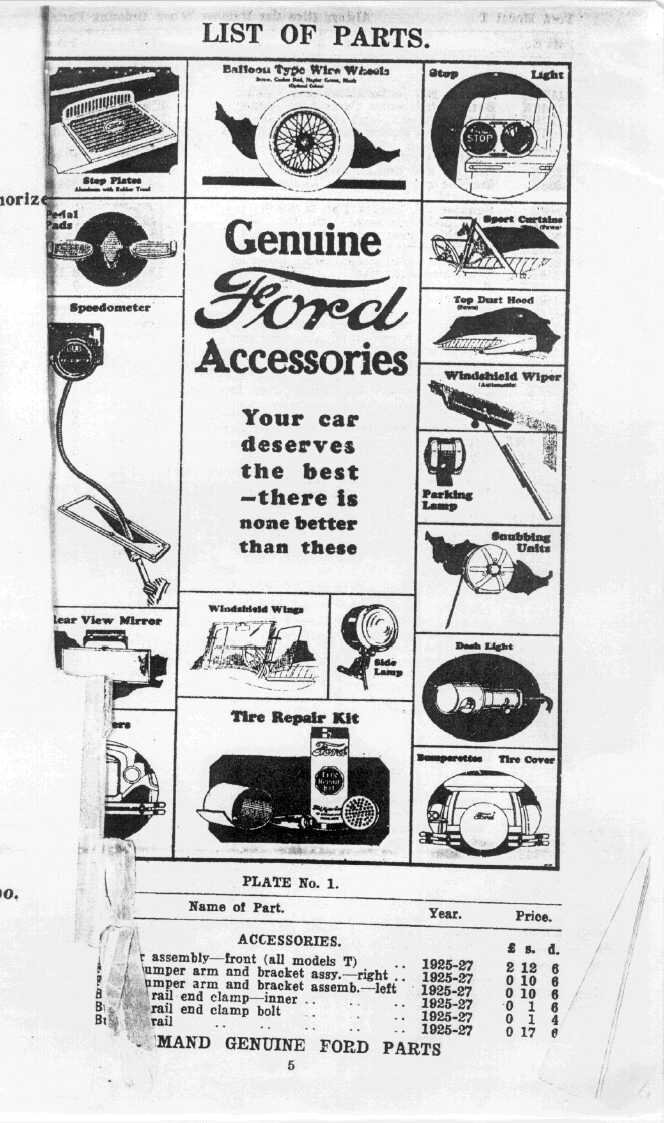
Although the Model T was not released with
a brake light, present day traffic conditions make it very unwise not to
have one. For one thing, few understand hand signals.
Accessory brake lights were available
with the later Model T's. This replaced the single tail/number plate light
with a dual arrangement consisting of the tail light as before, and a separate
brake light with the word "STOP" embossed in the glass lens.
From the Australian Ford parts catalog 1927. This can be downloaded
here.
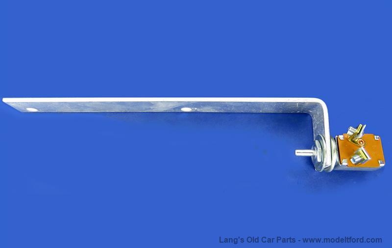
The next part of the installation was how
to switch the brake light. In the U.S. with their LHD cars, a switch was
mounted on the starter motor Bendix cover. A repro version of this is available
today:
Bendix cover switch senses the brake pedal moving outwards from
the transmission cover.
As the brake pedal is pressed down, the
cam which tightens the band around the brake drum inside the transmission,
also causes the pedal shaft to move outwards. It then begins to press against
the actuating rod of the switch.
However, this is obviously unsuitable
for RHD cars since the pedals are on the opposite side of the transmission
cover. Also, the brake pedal shaft moves inwards instead of outwards. This
would require the normally open switch to be replaced with a normally closed
type.
Another kind of switch operates on the
same principles, but instead of being secured to the Bendix cover, it is
secured using the transmission cover door screws. Again, if it was to be
modified for RHD, the switch would have to be a normally closed type.
Pedal moving outwards presses on the switch plunger.
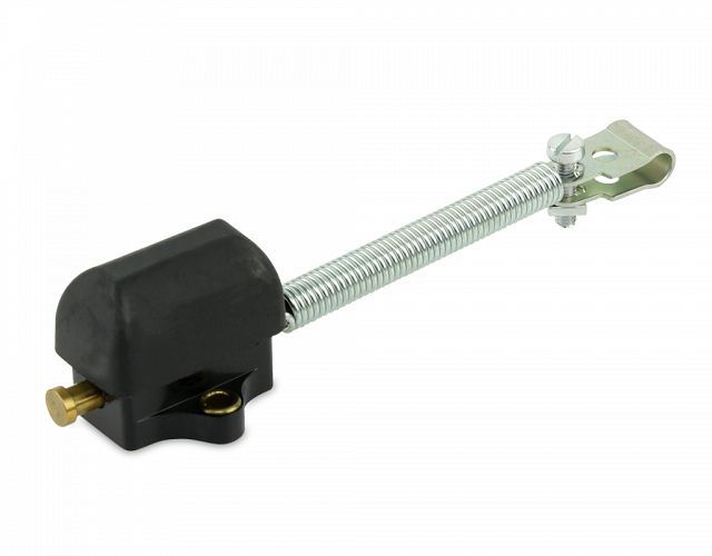
A third method is to ignore the sideways
movement of the brake pedal, but operate on the forward movement. An accessory
switch of this type became available in recent times, made by Fun Projects.
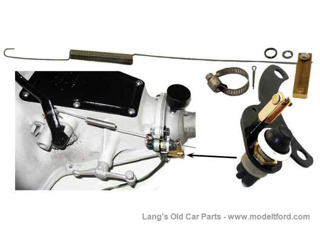
Fun Projects brake light switch.
As the brake pedal is pushed forwards,
the switch is actuated via the spring. The spring is necessary to allow
for the brake pedal to keep moving forward once the switch is fully depressed.
This particular switch can be used with RHD cars.
All these accessory brake switches are
widely available from Model T parts suppliers; Lang's obviously being one
of them. Model T owners have also created their own home made versions.
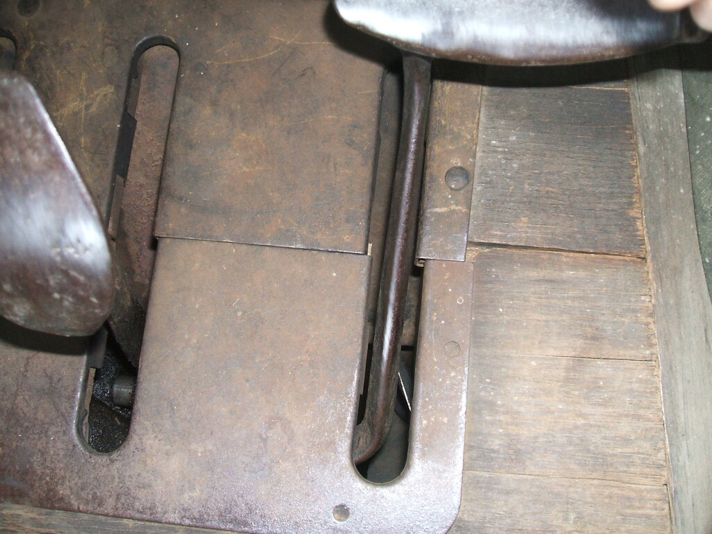
Unlike LHD cars, the brake pedal shaft moves inwards when the brake
is actuated. Two pin socket can be seen behind the brake pedal on the
body frame.
When it came time to equip my own Model
T with brake lights, some thought was given to how this might be done.
It is not clear how the RHD cars were originally fitted with a brake light
switch, since they are not shown in any catalog I have seen, and nor have
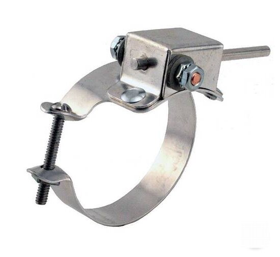
I seen any originals. Most owner attempts have been with the Hella type
switch, and a piece of wire running up to the brake pedal arm to actuate
it. It is a less elegant version of the Fun Projects switch and has been
around for a long time, intended for vintage car use.
This Hella switch has been often adapted for Model T use in Australia.
The method of having the switch on a bracket
mounted using the transmission door screws looked attractive initially.
Unfortunately, with the accessory oil screen in place, the screws were
just not long enough. Also, the stamping of the cover is such that it would
have to be mounted upside down, so that the bracket can be screwed down
flush. This is not possible with the oil screen. Also, one could be sceptical
of the cover being mounted upside down in terms of directing the oil onto
the drums. The stamping is such that oil drips off the middle, directly
above the gap in the bands. No doubt, with a modified bracket and longer
screws, this kind of switch could be made to work.
The Fun Projects switch was not yet available
back in 2003, but there's a good chance I would have used it had it been
so. I briefly toyed with using the Hella switch. A difficulty was with
how the pedal moves in the RHD cars, and also how to clamp the spring to
the brake pedal. Since the pedal arm is slightly tapered, any kind of clamp
would be difficult to secure. In one instance, I had seen that the owner
had drilled a hole through the brake pedal arm - something that no doubt
solves the problem, but I was loath to do. Also, the closer to the shaft,
the less movement there is to actuate the switch. My experience with this
switch in other Model T's is that it's difficult to keep adjusted correctly.
This is not a fault of the switch, but rather the difficulties of connecting
it to the brake pedal - which it was never designed for.
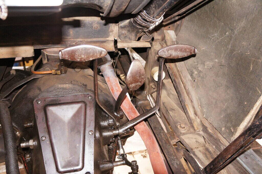
I also wanted to minimise extra parts that would inhibit access to the transmission - more parts to remove each time the bands were adjusted, etc. What I came up with was a micro switch mounted on the draught deflector, which was actuated by the brake pedal arm.
As brake pedal moves forward, it presses against the arm of the
micro switch.
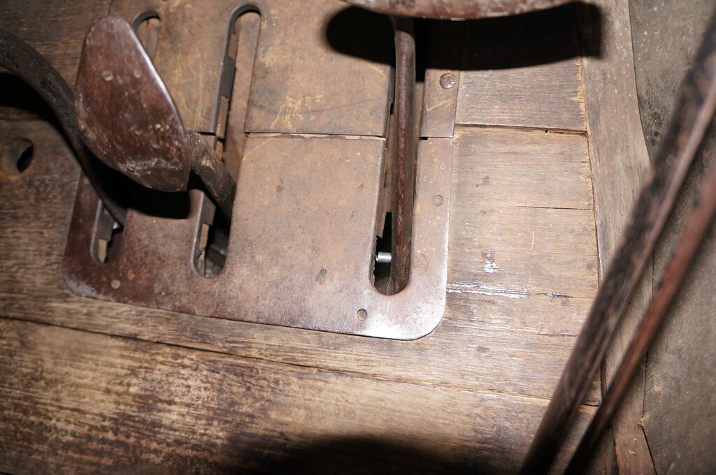
Close up view of how switch is mounted on a bracket on the draught
deflector.
Switch lever can be seen towards the lower part of the brake pedal
arm.
Since the switch was mounted on the upper floorboard, it had to be readily disconnectable when the floorboards were removed. For this, a short cable was fitted with a two pin bakelite plug. This plugs into a two pin socket mounted on the framework. The plug and socket I used are of the U.S. two flat pin style, since these are rugged enough and are designed for frequent use. Since this type of plug and socket is of limited in use in Australia, there would be no risk of someone plugging the brake light switch into the mains. One would have to question the logic of removing the floorboard from the car, taking it to a power point and plugging it in!
By and large, the switch was very reliable
since installing it in 2003, and using it up until the end of 2021. However,
once in a while, particularly when the brake was getting to the point of
needing adjustment, the switch lever would hook over the pedal arm and
get bent.
Thoughts were again made to an improved
switch. Drilling into the chassis or framework was something to be avoided,
and this limits the options. As mentioned before, I didn't want to make
use of the transmission door screws.
Clamping things to the brake pedal arm
is never reliable, and it's something else that has to be dismantled when
removing the brake pedal for band re-lining.
Magnetic (Hall effect, proximity sensor,
reed switch) or optical sensors are a possible option, and maybe one day
I might go down that path.
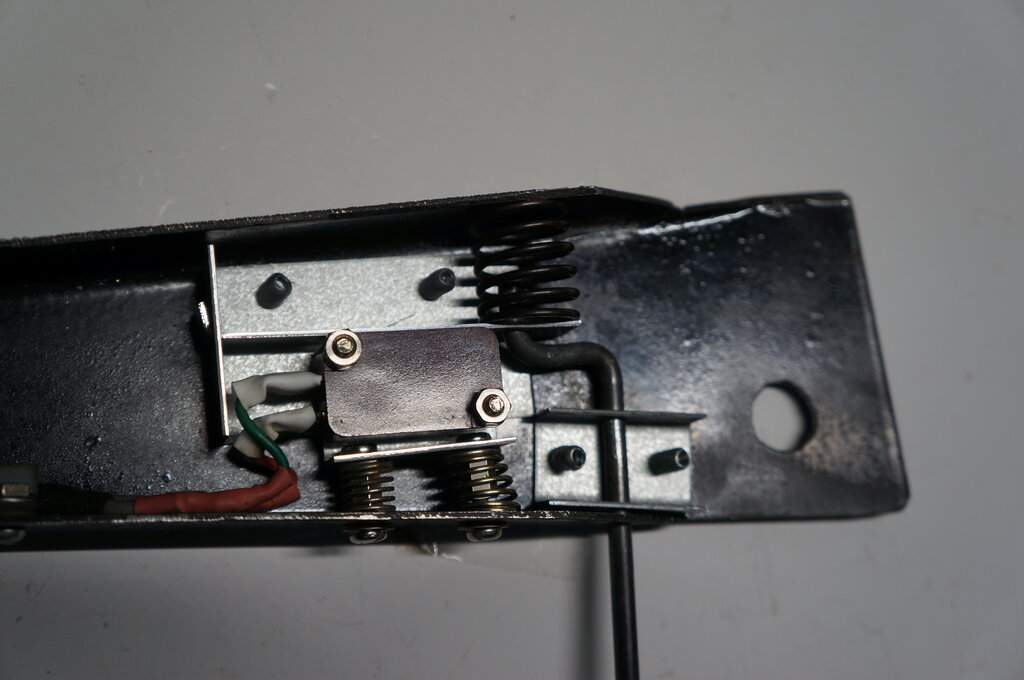
The spring can be seen just inside the lower part of the opening.
How the spring is mounted relative to the pedal arm.
An ordinary coil spring is used as the
fixed contact. It is mounted a few millimetres away from the back of the
pedal arm. As the brake is applied, the back of the arm touches the spring,
with the spring wiping against the side of the arm, the further the brake
pedal is pushed.
This completes the circuit to earth.
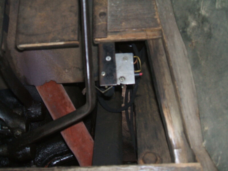
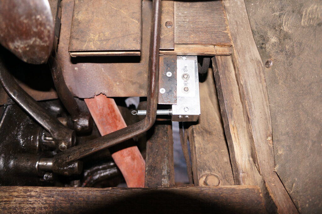
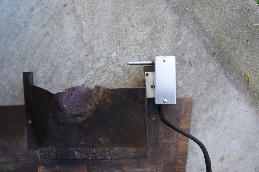
Because the brake lights work with a switched positive, and the switch operates with a switched negative, a relay was required. To accommodate this, a small aluminium box was made up which also supported the spring. The box mounting was made adjustable by means of a slotted bracket which was riveted to the draught deflector. Conveniently, the existing two pin plug and socket could be retained, since the only connections required to the wiring were still the 6V supply and switched output to the brake lights.
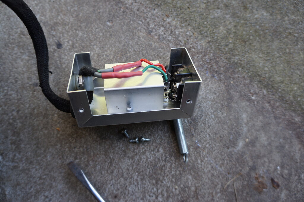
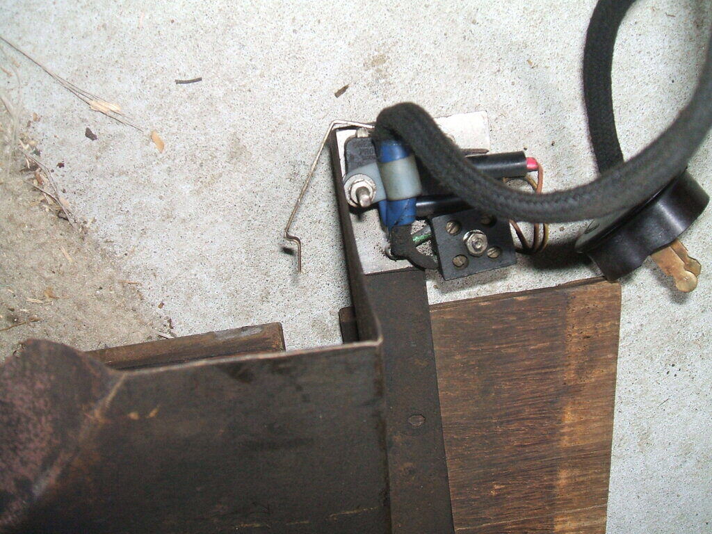
Inside the box. The relay is under the bracket, and the spring attaches
to a bakelite screw terminal strip.
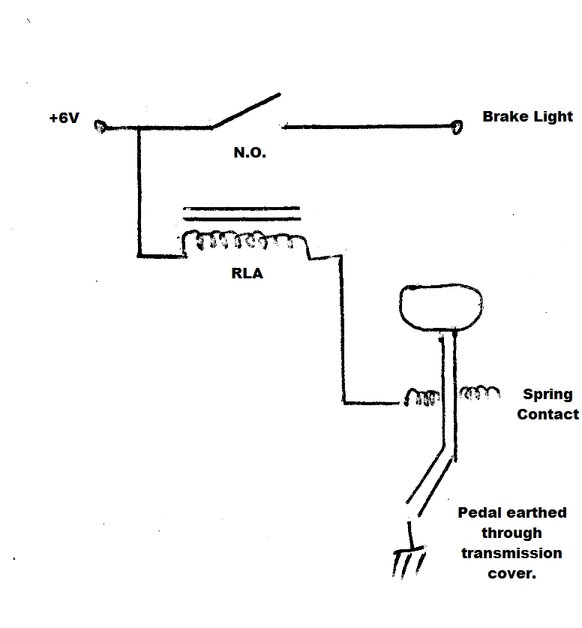
Circuit of what's inside the box.
The relay coil is switched by the pedal
touching the spring, and the normally open contacts complete the 6V supply
to the brake lights. The relay I used was made by Omron with a 6V coil,
and has four contacts rated at 5A. These were all paralleled.
Instead of the relay, it should be possible
to use a PNP power transistor (e.g. MJ2955) with a base resistor. The base
would be taken to earth via the base resistor, which would allow current
to flow from emitter to collector. I considered this, but since I had the
relay it was the easiest approach. Since the two pin plug and socket is
non polarised, the circuit will not work if the plug is in the wrong way
round, but no damage will result.
The new switch certainly works, and is
more rugged than the micro switch. A limitation is how good the contact
is between the spring and brake pedal, and with only 6V it can be imagined
that any oxide or dirt would make for unreliable operation. The wiping
action should keep these parts clean, but only time will tell.
Underside of floorboard.
I briefly experimented with an optical
switch. A red LED shined onto an LDR via a reflective surface. The reflective
surface was to be on the brake pedal arm. As the LDR resistance dropped,
base current to a switching transistor would increase, actuating a relay.
While the concept worked, the problem
was a high standby current because some relay current is flowing before
the relay actually pulls in. Also, the circuit would be influenced by ambient
light. So, back to the mechanical sensor.
The two body bolts I wanted to use required a rather complicated bracket to be made up. With two different angles, and a tapered shape, it was easier to make up a cardboard template first. Once this fitted satisfactorily, I cut out a piece of scrap steel and bent up the bracket. With a bit of cutting and filing it fitted perfectly.
The next thing was what to use for the
rod bearing against the brake pedal shaft. After much looking around, I
found a steel tent peg that was just right. This required to be spring
loaded and supported on the bracket, and so a suitable bracket was made
up for that.
Then a lever to act as pivot was required,
and finally an adjustable mount for the micro switch.
Micro switch mounted on spring loaded bracket to allow adjustment
in the car.
By the time I had finished it, you could say it was a mechanical nightmare of overkill. It was a lot of intricate bracket making.
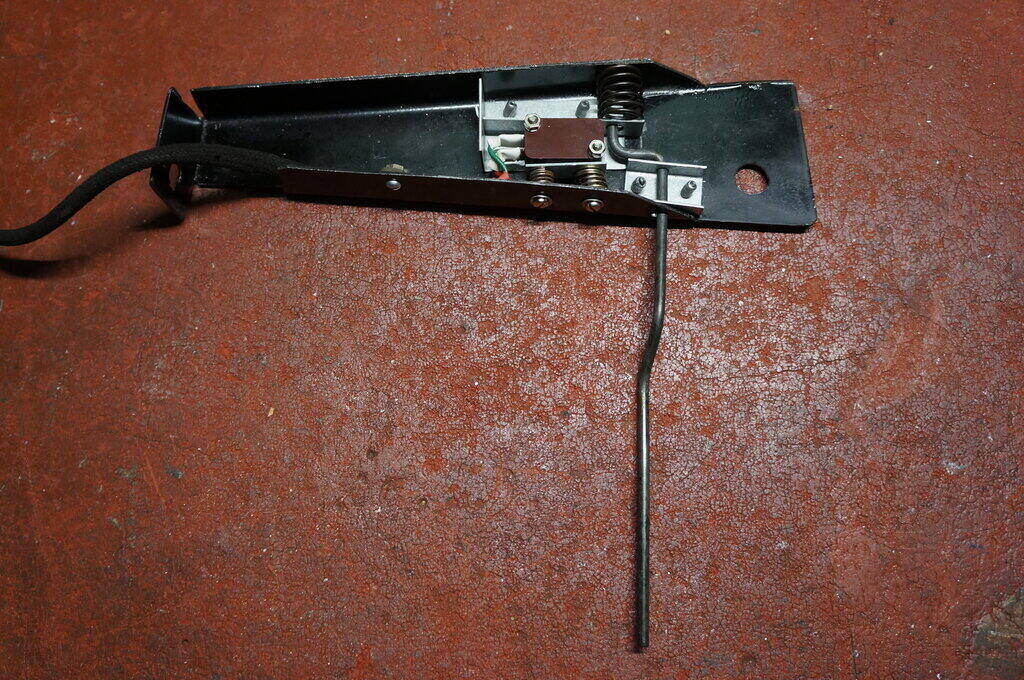
Completed switch.
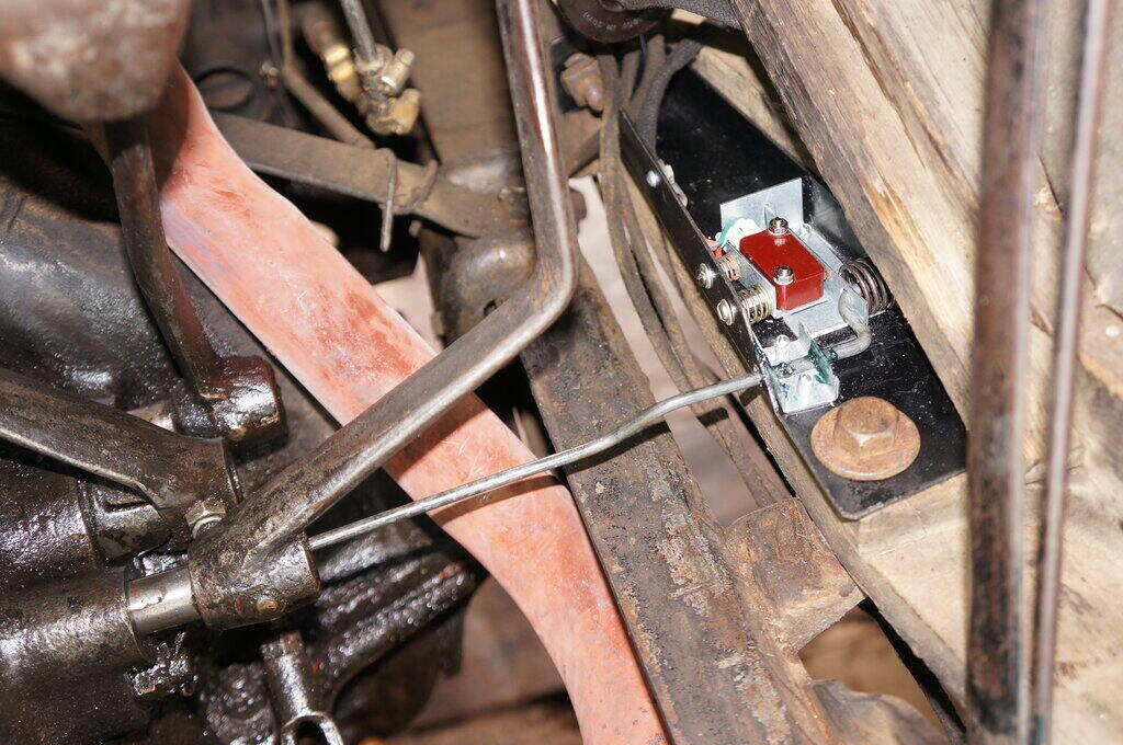
Finally mounted in the car.